
2 layers101.5 × 83 mm

 gidim/e61-gauge8
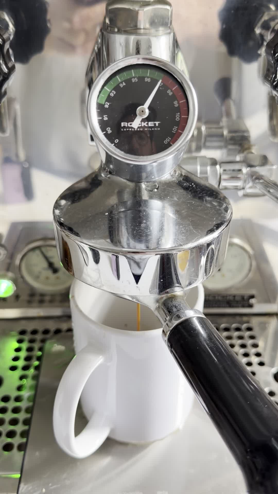
An analog temperature gauge for E61 espresso machines. A custom PCB drives a VID6606 stepper motor gauge needle, reading temperature from an NTC thermistor.
Chip and transistor is an open-source printed circuit board by gidim, from the gidim/e61-gauge repository on GitHub. It is a 2-layer board of 14.6 × 13.6 mm with 15 parts on 40 nets, routed with 134 tracks and 11 vias.
It is built around the 2N2222A. Its parts include 3 capacitors, 3 resistors, 2 ICs, 1 transistor and 1 connector. It belongs with the nRF52 and nRF5x boards of this library.
An analog temperature gauge for E61 espresso machines. A custom PCB drives a VID6606 stepper motor gauge needle, reading temperature from an NTC thermistor. The gauge connects via BLE to a web app for calibration and real-time monitoring.
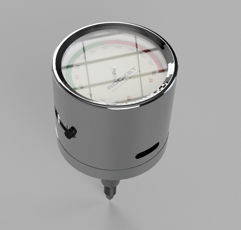
The dial has a non-linear scale (0–150°C) with an expanded green zone at 92–97°C for precision in the critical temperature range.
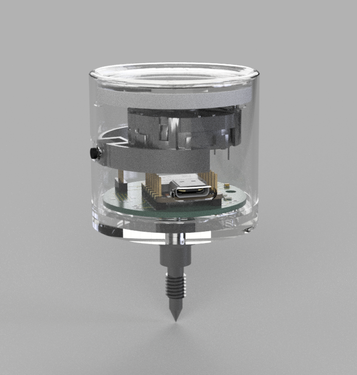
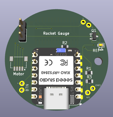
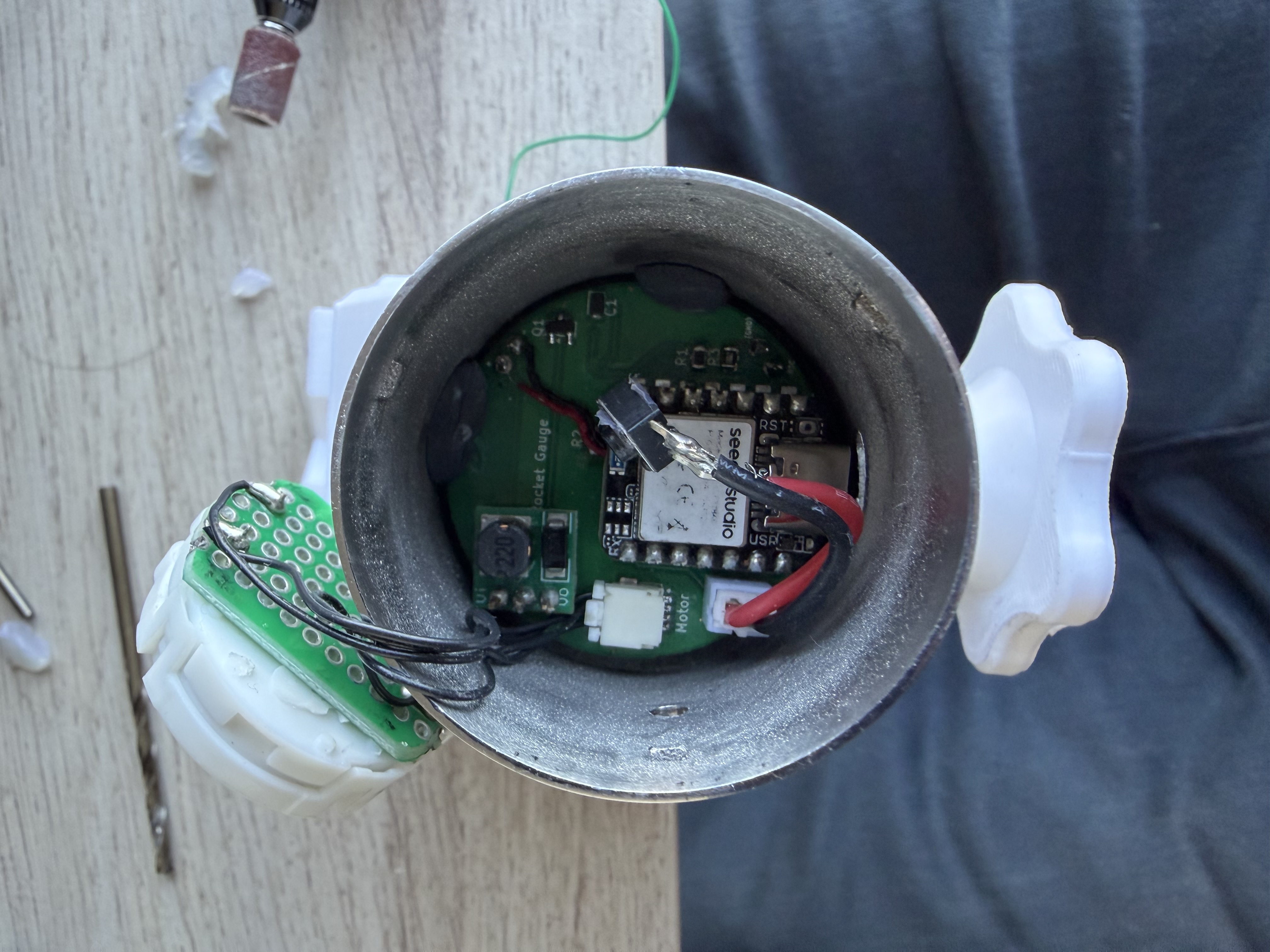
Built around a Seeed Studio XIAO nRF52840. Key components:
The PCB was custom manufactured and assembled. The dial face is a custom design with a non-linear scale — the green zone (92–97°C) is expanded for precision while the cold and hot extremes are compressed. The SVG is in hardware/dial_face.svg. KiCad source files, schematic, and BOM are in hardware/.
The enclosure was SLM (selective laser melting) 3D printed in metal and hand-sanded to achieve the chrome-like finish. Fusion 360 source (enclosure/gauge_enclosure.f3z), STEP, and STL files are in enclosure/.
The schematic uses two non-standard libraries included in libraries/:
XIAO_nRF52840.pretty/ — footprint for the XIAO nRF52840 moduleSeeed_Studio_XIAO_Series/ — schematic symbolAdd both to your KiCad library paths before opening the project.
Arduino sketch in firmware/gauge/. Uses the Adafruit nRF52 BSP.
Dependencies (install via Arduino Library Manager):
Adafruit TinyUSBAdafruit nRF52 BSP (includes bluefruit, Adafruit_LittleFS, InternalFileSystem)AccelStepperThe gauge supports BLE serial commands for calibration, homing, sweep tests, and configuration. See firmware/gauge/commands.h for the full command set.
A Web Bluetooth app in webapp/ — open index.html in Chrome (Android, macOS, or Windows). iOS Safari does not support Web Bluetooth.
Connect to the gauge over BLE to monitor temperature, set calibration points, and control the needle.
Python utilities in tools/ for serial-based development and testing.
pip install -r tools/requirements.txt
python tools/serial_terminal.pyvid6606/ contains a standalone sweep demo sketch and a copy of the SwitecX25 stepper library used for the VID6606 driver.
A minimal Arduino sketch for validating NTC thermistor readings independently of the main firmware.
| Qty | Value | Footprint | References |
|---|---|---|---|
| 2 | 0.1uF | Capacitor_SMD:C_0805_2012Metric | C2, C3 |
| 2 | 10k | Resistor_SMD:R_0805_2012Metric | R2, R3 |
| 1 | 10uF | Capacitor_Tantalum_SMD:CP_EIA-1608-08_AVX-J | C1 |
| 1 | 1k | Resistor_SMD:R_0805_2012Metric | R1 |
| 1 | 2N2222A | Package_TO_SOT_SMD:SOT-23 | Q1 |
| 1 | 5v Boost | Connector_PinHeader_2.54mm:PinHeader_1x03_P2.54mm_Vertical | J1 |
| 1 | BTN | TestPoint:THT_2PAD_SOLDER_P5.08MM_GIDEON | SW1 |
| 1 | Battery | TestPoint:THT_2PAD_SOLDER_P5.08MM_GIDEON | Battery1 |
| 1 | NTC | TestPoint:THT_2PAD_SOLDER_P5.08MM_GIDEON | NTC1 |
| 1 | Stepper_Motor_bipolar | Connector_JST:JST_SM04B-SRSS-TB_LF__SN_ | M1 |
| 1 | VID6606 | Package_SO:SOIC-28W_7.5x17.9mm_P1.27mm | U2 |
| 1 | XIAO-nRF52840-DIP | XIAO_nRF52840:XIAO-nRF52840-DIP | U3 |
The 14 most common of 15 parts.

lynchaj/rhyophyre
Single Board Computer featuring Zilog Z180 processor and NEC µPD7220 Graphics Display Controller

alvaroalea/QL_QsoundQprint_clone
A clone board of the Sound card for the Sinclair QL Computer.

profdc9/NixieClock
A Nixie clock that uses IN-14 tubes and very generic components that can be easily sourced.

jensma-de/MM58167-ISA-RTC
RTC module for the ISA slot. With schematics, project files in kicad and open source software to drive the clock.


cnobile2012/Li-IonBatteryProtection
Circuit to protect Li-Ion and Li-Po batteries at the cell level.

It measures 14.6 × 13.6 mm and has 2 copper layers, 1.6 mm thick.
15 parts, built around the 2N2222A. The full list of its parts is on this page, with links to each part's symbol and footprint where PCBKit's library has them.
From the gidim/e61-gauge repository on GitHub, at the commit this page was made from: the board is hardware/chip_and_transistor.kicad_pcb and its schematic hardware/chip_and_transistor.kicad_sch. PCBKit opens the board in the browser, with nothing to install.
Its repository states no licence, so its author keeps all rights: ask gidim before reusing the design.