2 layers33.2 × 18.5 mm
T3pa loadcell mod v1
foriequal0/t3pa-loadcell-mod
Thrustmaster T3PA pedal load cell mod without a dead zone
12 parts5

 foriequal0/t3pa-loadcell-mod5
Thrustmaster T3PA pedal load cell mod without a dead zone
T3pa loadcell mod v2 is an open-source printed circuit board by foriequal0, from the foriequal0/t3pa-loadcell-mod repository on GitHub. It is a 2-layer board of 35 × 20 mm with 23 parts on 16 nets, routed with 89 tracks and 16 vias.
It is built around the TLV9152ID and ES1J. Its parts include 9 resistors, 3 capacitors, 3 connectors, 2 ICs and 1 diode. It belongs with the sensors and measurement boards of this library.


I've designed a PCB for a better design. I've fixed my mistakes.
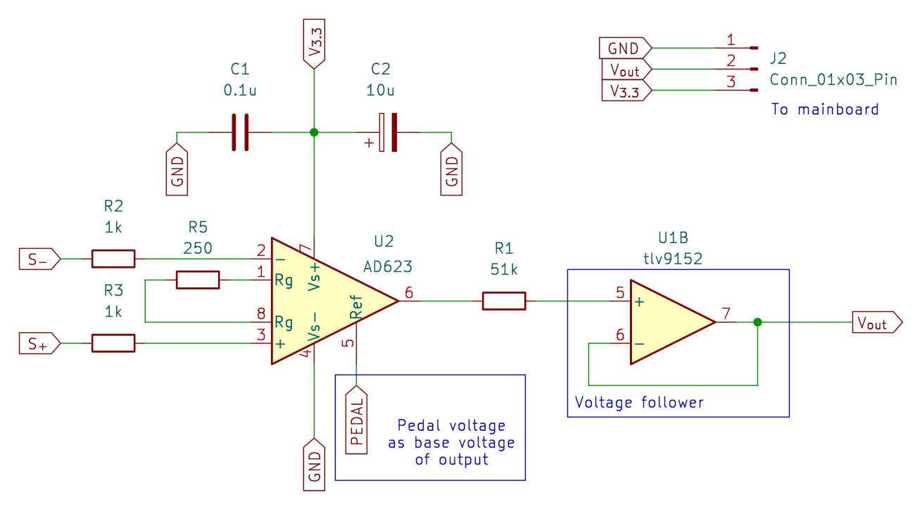
The idea is simple: Use amplifier's REF pin to add the pedal's voltage.
Electrical details are the same with v0.
I've used AD620 before, but I've changed it to AD623 which has a rail-to-rail characteristics. I've chosen 240 Ohm resistor to have 400x gain according to the datasheet.
While skimming through the datasheet, I've noticed Ref pin is used to control the output voltage offset. So I decided to abuse it to add the potentiometer.
I've ordered the PCB from JLCPCB. Hand-soldering was not that hard.
I've changed conical rubber shock absorber with M6x2.1x27x35 compression spring seat because why not? It can be mounted using M6 bolt. It has the right amount of compression force than the rubber shock absorber. I've removed the cap to reduce the height.
The rest is the same with the v0.
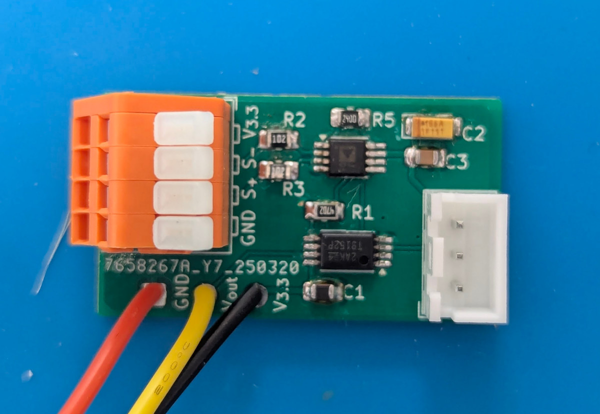
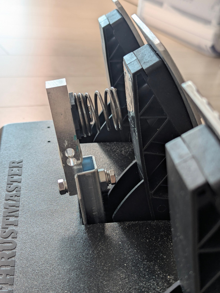
Much better than v0. It's smaller, simpler, and less noisy.
| Qty | Value | Footprint | References |
|---|---|---|---|
| 4 | 51k | Resistor_SMD:R_0805_2012Metric_Pad1.20x1.40mm_HandSolder | R1, R2, R3, R4 |
| 2 | 0.1u | Capacitor_SMD:C_0805_2012Metric_Pad1.18x1.45mm_HandSolder | C1, C3 |
| 2 | 1k | Resistor_SMD:R_0805_2012Metric_Pad1.20x1.40mm_HandSolder | R6, R7 |
| 1 | 10u | Capacitor_Tantalum_SMD:CP_EIA-3216-10_Kemet-I_Pad1.58x1.35mm_HandSolder | C2 |
| 1 | 16k | Resistor_SMD:R_0805_2012Metric_Pad1.20x1.40mm_HandSolder | R8 |
| 1 | 200 | Resistor_SMD:R_0805_2012Metric_Pad1.20x1.40mm_HandSolder | R5 |
| 1 | 2k | Resistor_SMD:R_0805_2012Metric_Pad1.20x1.40mm_HandSolder | R9 |
| 1 | Conn_01x03_Pin | Connector_Wire:SolderWire-0.25sqmm_1x03_P4.2mm_D0.65mm_OD1.7mm | J2 |
| 1 | Conn_01x03_Socket | Connector_JST:JST_XH_B3B-XH-A_1x03_P2.50mm_Vertical | J3 |
| 1 | ES1J | Diode_SMD:D_SMA | D1 |
| 1 | INA317 | Package_SO:MSOP-8_3x3mm_P0.65mm | U2 |
| 1 | LoadCell | TestPoint:TestPoint_Pad_D1.0mm | TP1 |
| 1 | Offset | TestPoint:TestPoint_Pad_D1.0mm | TP4 |
| 1 | Pedal | TestPoint:TestPoint_Pad_D1.0mm | TP3 |
| 1 | PedalRaw | TestPoint:TestPoint_Pad_D1.0mm | TP2 |
| 1 | SolderJumper_2_Open | Jumper:SolderJumper-2_P1.3mm_Open_RoundedPad1.0x1.5mm | JP1 |
| 1 | Terminal_01x04 | TerminalBlock_WAGO:TerminalBlock_WAGO_233-504_2x04_P2.54mm | J1 |
| 1 | tlv9152 | Package_SO:TSSOP-8_4.4x3mm_P0.65mm | U1 |
foriequal0/t3pa-loadcell-mod
Thrustmaster T3PA pedal load cell mod without a dead zone

foriequal0/t3pa-loadcell-mod
Thrustmaster T3PA pedal load cell mod without a dead zone

janni0609/DC-Load
A programmable DC electronic load built on the Raspberry Pi Pico 2 (RP2350). It sinks a user-defined current from a DC source under test and measures voltage, current, power, capacity, and energy in real time on a…

fotherja/Grid_Tie_Inverter_V5
Please refer to my site ( www.jamesfotherby.com ) where this project is being documented in detail


kuvychko/universal-nixie-display
Six IN-14 Nixie tubes, an A101 dekatron and an ESP32 touchscreen in one desktop display: a clock, timer and toy, and a numeric display for a computer over USB.

supernova-10/Kubits-programmable-magnets
Kubit is my Final Year Project (FYP) — a modular reconfigurable robot that uses programmable magnets, gears, and custom PCB-based control to achieve untethered actuation and reconfiguration.

alplix/yarrow
Open firmware for the FNIRSI GC-03 radiation detector

arthithadee/Sonar_transmitter
AZHAI is a software-defined sonar transmitter firmware designed for autonomous underwater vehicles (AUVs).

blind-reckoning/Reckoner
Turns press-and-hold motorised blinds into Home Assistant covers. One Reckoner per blind, hidden in the wall box behind the buttons you already have.
It measures 35 × 20 mm and has 2 copper layers, 1.6 mm thick.
23 parts, built around the TLV9152ID and ES1J. The full list of its parts is on this page, with links to each part's symbol and footprint where PCBKit's library has them.
From the foriequal0/t3pa-loadcell-mod repository on GitHub, at the commit this page was made from: the board is t3pa-loadcell-mod-v2/t3pa-loadcell-mod-v2.kicad_pcb and its schematic t3pa-loadcell-mod-v0/AD620_module.kicad_sch. PCBKit opens the board in the browser, with nothing to install.
Its repository states no licence, so its author keeps all rights: ask foriequal0 before reusing the design.