4 layers85 × 76 mm
Valvedrivers
npgo22/APRL-Electrical-New
To use the board templates, set KICADUSERTEMPLATEDIR by:
145 parts

 FLRHW/Desk_controller
Standing desk controller - Touch display as HMI and servo motor interface
Desk controller is an open-source printed circuit board by FLRHW, from the FLRHW/Desk_controller repository on GitHub. It is a 2-layer board of 100 × 51.3 mm with 105 parts on 84 nets, routed with 506 tracks and 71 vias.
It is built around the STM32G431K8T6, VNH7070AS and USBLC6-2SC6, with the RC0603JR-130RP, AC0603KRX7R9BB104 and AC0603FR-0710KL among its other parts. Its parts include 27 capacitors, 15 resistors, 8 connectors, 4 ICs and 1 diode. It belongs with the robots and motor control boards and the STM32 boards of this library.


A custom KiCad PCB design for a motorised sit–stand desk controller with a touchscreen human–machine interface (HMI).
Hardware design · Online documentation · Firmware repository · 3D renders · Manufacturing outputs
This repository contains the KiCad hardware design for a desk controller that brings together the user interface, control electronics, motor interface and end-of-travel sensing on one board. It is intended to interface with an external desk mechanism, motor/gearbox/encoder assembly and power supply. The project started as a personal engineering build; the design is published so others can inspect, learn from, or adapt it at their own risk.
Beyond the intended application, the repository documents the design workflow—from system-level architecture and hierarchical schematics through PCB layout, design checks and automated fabrication/assembly deliverables.
Project scope: This repository documents the controller hardware. The desk mechanism, motor assembly and external power supply are shown for context and are not part of the PCB design. Do not assume the design is production-ready or safe to connect to a desk without independent electrical, mechanical and functional validation.
The design is organised into these functional blocks:
| Block | Purpose |
|---|---|
| Microcontroller / control logic | Coordinates the user interface and motor-control signals. |
| Touch display | Local human–machine interface for operating the desk. |
| Servomotor interface | Motor power-drive interface and encoder signal conditioning. |
| Limit-switch interface | Connections and conditioning for end-of-travel signals. |
| 3.3 V DC/DC conversion | Low-voltage supply for the control electronics. |
| Power-supply interface | Connection to the external power source. |
See System_overview.kicad_sch and Block_diagram.kicad_sch for the system-level drawings. The hierarchical schematic files provide the electrical details.
The renders below are generated from the KiCad PCB design as part of the automated documentation workflow.
| Top view | Bottom view |
|---|---|
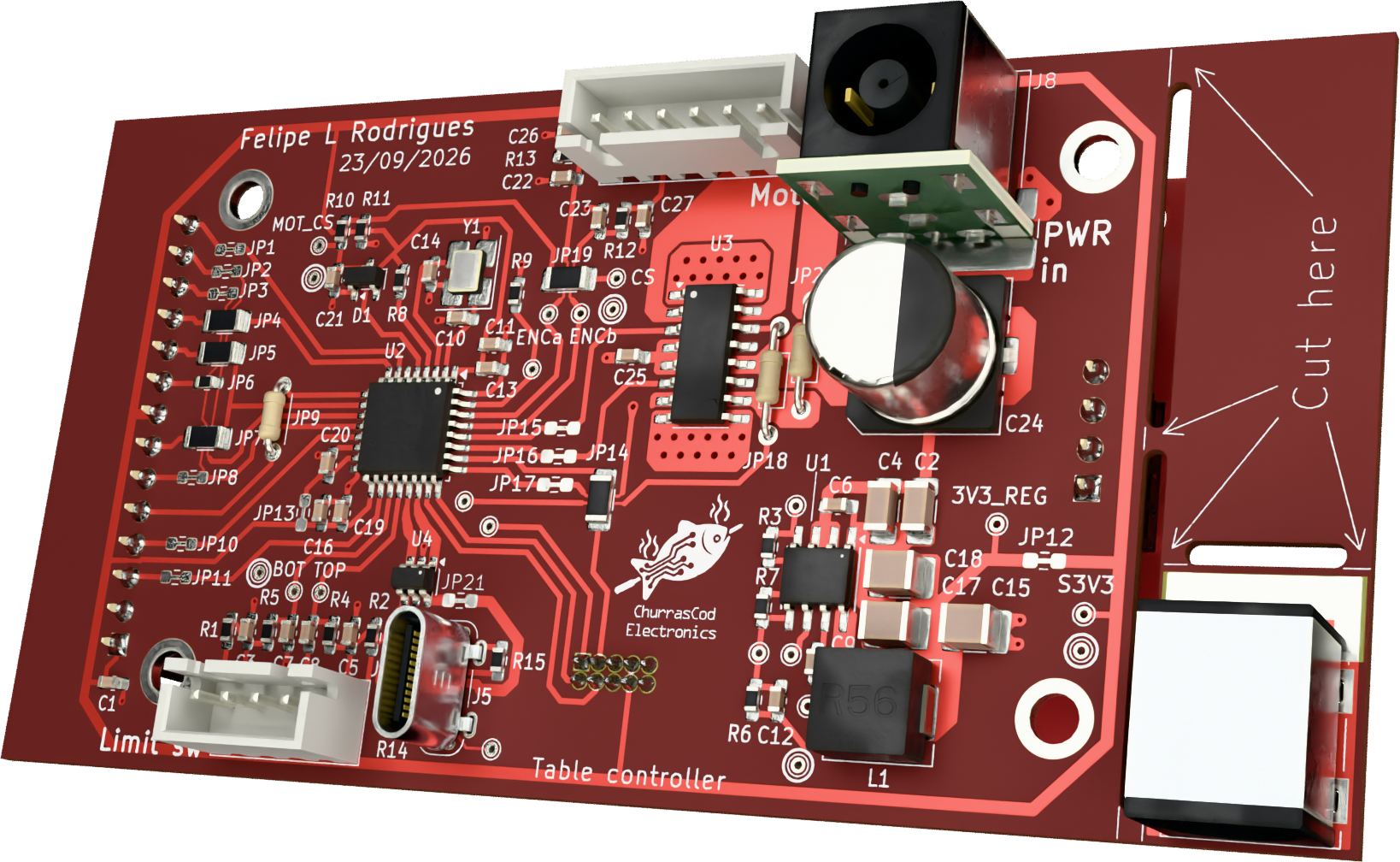 | 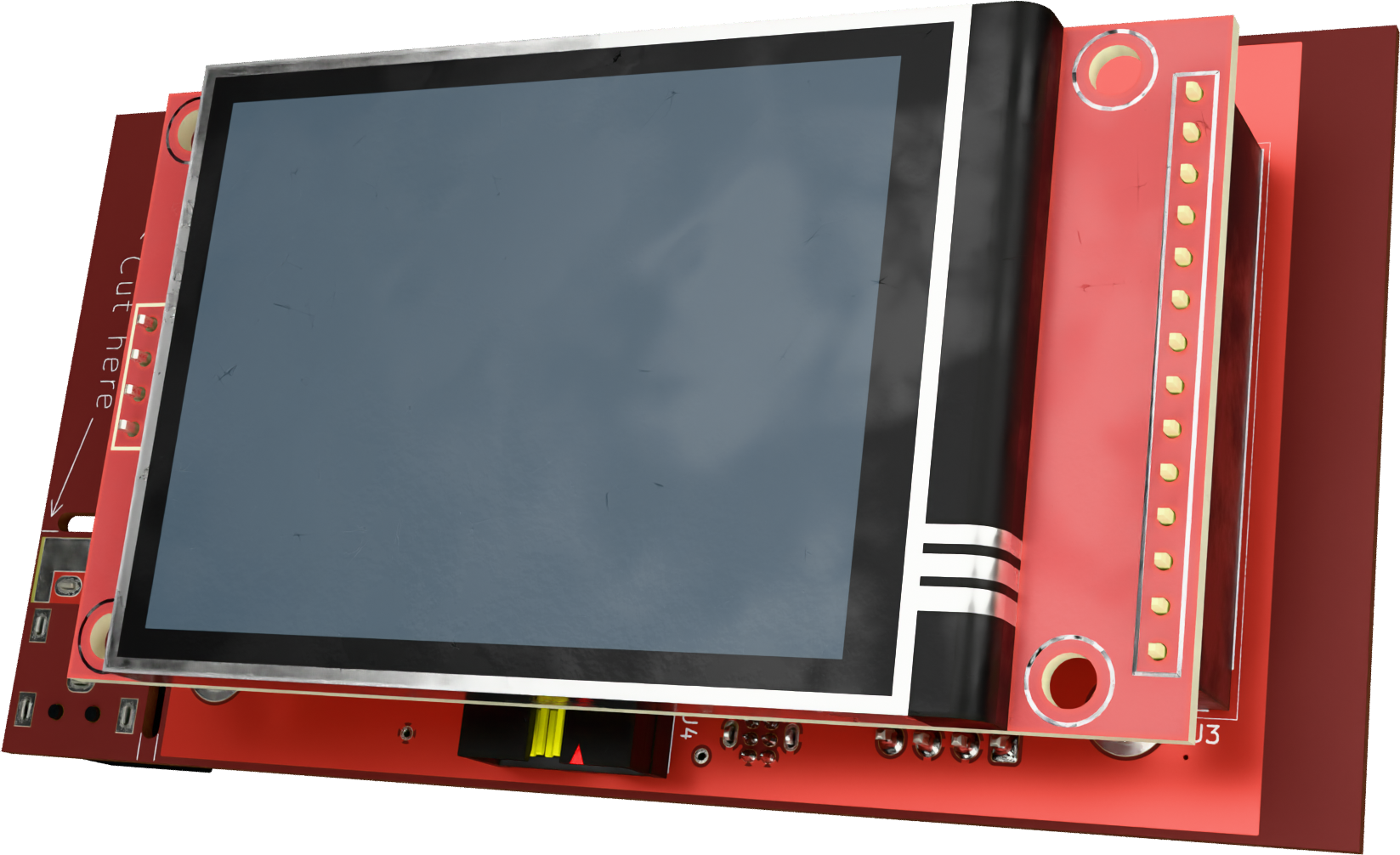 |
Additional renders and design files:
The generated files are published to make the design easier to review and reproduce. Their presence does not imply that the PCB, assembly or motor-control system has been manufactured, tested or validated. Check the current outputs and reports before considering fabrication.
The firmware is developed separately in FLRHW/Desk_controller_source. It is under development and not yet usable. Please consult that repository for its latest implementation and status; firmware progress is intentionally not duplicated here to avoid maintaining two status reports.
| Path | Description |
|---|---|
Desk_controller.kicad_pro | KiCad project settings. |
Desk_controller.kicad_sch | Root hierarchical schematic. |
Desk_controller.kicad_pcb | PCB layout. |
Microcontroller.kicad_sch | Control electronics. |
Display.kicad_sch | Display interface. |
Servomotor_interface.kicad_sch | Motor driver and encoder interface circuitry. |
Limit_switch_interface.kicad_sch | Limit-switch interface circuitry. |
DCDC_converter_3V3.kicad_sch | 3.3 V supply stage. |
Interface_*.kicad_sch | External connection/interface drawings. |
output/ | Generated documentation and manufacturing exports. |
config.kibot.yaml | KiBot output and documentation configuration. |
.github/workflows/, ci/, scripts/, templates/ | Automated generation, helper scripts and drawing worksheets inherited from the KiCad starter. |
Install KiCad 10.
Clone the repository:
git clone https://github.com/FLRHW/Desk_controller.git
cd Desk_controller
Open Desk_controller.kicad_pro in KiCad.
Open the schematic editor to navigate the hierarchical sheets, or the PCB editor to inspect the board layout.
Run KiCad's Electrical Rules Checker (ERC) and Design Rules Checker (DRC) after making changes, and review the reports before fabricating a board.
This is an existing project, not a fresh copy of the starter template: you do not need to run the template's project-creation instructions to open it.
The repository uses KiBot and GitHub Actions to generate design documentation and manufacturing outputs. Depending on the active config.kibot.yaml settings and the latest completed workflow, output/ can include:
Browse the online documentation, or open output/index.html locally after cloning. The website is updated by successful default-branch builds when GitHub Pages publishing is enabled and shows the latest deployed outputs; use a release tag for a fixed snapshot. The original template's documentation contains more details on the export system: FLRHW KiCad Starter.
Before ordering PCBs: inspect the actual Gerbers, drill data, stack-up, BOM and fabrication notes. Generated outputs and a passing automation run are not substitutes for electrical and safety verification; inspect ERC/DRC reports separately.
This repository contains an evolving hardware design. The presence of schematics, PCB files or manufacturing exports does not imply that a physical prototype has been built, tested or validated. Anyone building or operating hardware based on this design must independently assess the risks, verify that the complete system is safe for its intended use, and implement and validate appropriate safeguards before putting it into service. The availability of design files or manufacturing outputs is not evidence of safety or fitness for use. For firmware progress and readiness, refer to the firmware repository.
Motorised desk systems can cause injury or property damage. Before operating hardware based on this design, independently verify power-stage ratings, polarity and protection; limit-switch behaviour; motor direction and feedback; fault handling; and the ability to stop motion reliably. Never rely on software alone as the sole protection against unintended travel.
In the author's personal installation, a manually operated power-disconnect switch is fitted upstream of the power supply feeding the controller. This arrangement is described for reference only and has not been established as a sufficient safety measure for other installations.
Anyone reproducing or adapting this design is responsible for independently assessing the hazards of their complete system, implementing appropriate protective measures, and verifying their effectiveness before use. No particular safety arrangement is prescribed or guaranteed by this project.
This repository contains material covered by two separate licences, according to the origin and purpose of the files:
LICENSE file contains the hardware licence text.LICENSE-MIT file contains the corresponding MIT licence and notices.These licences apply to their respective materials; the presence of both files does not mean that the entire repository is offered under a choice of either licence. Third-party dependencies or assets may have their own terms. The firmware is maintained separately and is subject to the licensing terms in that repository.
Disclaimer: This is a personal engineering project shared as is, without warranty of safety, fitness for a particular purpose, completeness or correct operation. Anyone reusing, building, modifying or operating the design is responsible for their own engineering review, applicable regulatory requirements, testing and safeguards. The applicable licence texts govern warranty disclaimers and limitations of liability; this summary does not replace their terms.
| Qty | Value | Footprint | References |
|---|---|---|---|
| 21 | TestPoint | TestPoint:TestPoint_THTPad_D1.0mm_Drill0.5mm | TP1, TP2, TP3, TP4, TP10, TP11, TP12, TP13, TP14, TP15, TP16, TP17, TP18, TP19, TP20, TP21 +5 |
| 12 | 0R | Personal:Jumper_0603 | JP1, JP2, JP3, JP8, JP10, JP11, JP12, JP13, JP15, JP16, JP17, JP21 |
| 7 | 100n | Capacitor_SMD:C_0603_1608Metric_Pad1.08x0.95mm_HandSolder | C1, C6, C9, C13, C19, C20, C25 |
| 5 | 0R | Resistor_SMD:R_1206_3216Metric_Pad1.30x1.75mm_HandSolder | JP4, JP5, JP7, JP14, JP19 |
| 5 | 10k | Resistor_SMD:R_0603_1608Metric_Pad0.98x0.95mm_HandSolder | R1, R2, R7, R8, R9 |
| 5 | 1n | Capacitor_SMD:C_0603_1608Metric_Pad1.08x0.95mm_HandSolder | C7, C8, C21, C22, C23 |
| 5 | 2k2 | Resistor_SMD:R_0603_1608Metric_Pad0.98x0.95mm_HandSolder | R4, R5, R10, R12, R13 |
| 4 | 10n | Capacitor_SMD:C_0603_1608Metric_Pad1.08x0.95mm_HandSolder | C3, C5, C26, C27 |
| 3 | 22u | Capacitor_SMD:C_1210_3225Metric_Pad1.33x2.70mm_HandSolder | C15, C17, C18 |
| 2 | 0R | Resistor_SMD:R_0603_1608Metric_Pad0.98x0.95mm_HandSolder | JP6, JP20 |
| 2 | 0R | Resistor_THT:R_Axial_DIN0204_L3.6mm_D1.6mm_P7.62mm_Horizontal | JP18, JP22 |
| 2 | 1u | Capacitor_SMD:C_0603_1608Metric_Pad1.08x0.95mm_HandSolder | C11, C16 |
| 2 | 22p | Capacitor_SMD:C_0603_1608Metric_Pad1.08x0.95mm_HandSolder | C10, C14 |
| 2 | 4.7u | Capacitor_SMD:C_1206_3216Metric_Pad1.33x1.80mm_HandSolder | C2, C4 |
| 2 | 5k1 | Resistor_SMD:R_0603_1608Metric_Pad0.98x0.95mm_HandSolder | R14, R15 |
| 1 | 01x04 socket | Connector_PinSocket_2.54mm:PinSocket_1x04_P2.54mm_Vertical | J2 |
| 1 | 01x14 socket | Connector_PinSocket_2.54mm:PinSocket_1x14_P2.54mm_Vertical | J3 |
| 1 | 0R | Resistor_THT:R_Axial_DIN0204_L3.6mm_D1.6mm_P5.08mm_Horizontal | JP9 |
| 1 | 0R | Personal:Wire_9.603mm | JP23 |
| 1 | 0R | Personal:Wire_6.310mm | JP24 |
| 1 | 0R | Personal:Wire_9.532mm | JP25 |
| 1 | 0R | Personal:Wire_6.853x8.890mm | JP26 |
| 1 | 10u | Personal:L_Bourns_SRP6540 | L1 |
| 1 | 20 MHz | Crystal:Crystal_SMD_3225-4Pin_3.2x2.5mm_HandSoldering | Y1 |
| 1 | 220u | Capacitor_SMD:CP_Elec_10x10 | C24 |
| 1 | 23.2k | Resistor_SMD:R_0603_1608Metric_Pad0.98x0.95mm_HandSolder | R6 |
| 1 | 33p | Capacitor_SMD:C_0603_1608Metric_Pad1.08x0.95mm_HandSolder | C12 |
| 1 | 64.9k | Resistor_SMD:R_0603_1608Metric_Pad0.98x0.95mm_HandSolder | R3 |
| 1 | 820 | Resistor_SMD:R_0603_1608Metric_Pad0.98x0.95mm_HandSolder | R11 |
| 1 | B4B XH A | Connector_JST:JST_XH_B4B-XH-A_1x04_P2.50mm_Vertical | J1 |
| 1 | B6B XH A | Connector_JST:JST_XH_B6B-XH-A_1x06_P2.50mm_Vertical | J7 |
| 1 | BAV99 | Package_TO_SOT_SMD:SOT-23 | D1 |
| 1 | DC barrel assy | Personal:Dell_barrel_assy | J8 |
| 1 | Dell DC jack | Personal:Dell DC jack | J6 |
| 1 | HX JN1.27-2x5 WZ H4.9 | Personal:JN1.27-2x5 WZ H4.9 | J4 |
| 1 | LMR380x0 | Personal:Texas_HSOP-8-1EP_3.9x4.9mm_P1.27mm_ThermalVias_w_step | U1 |
| 1 | STM32G431K8T | Package_QFP:LQFP-32_7x7mm_P0.8mm | U2 |
| 1 | TFT_2.4in_320x240 | Personal:Display_240x320_ILI9341_2.4in_no_pads | TFT1 |
| 1 | USBLC6-2SC6 | Package_TO_SOT_SMD:SOT-23-6 | U4 |
| 1 | USB_C_Receptacle_USB2.0_16P | Personal:USB_C_socket_16P_vertical | J5 |
| 1 | VNH7070 | Package_SO:JEITA_SOIC-16_3.9x9.9mm_P1.27mm | U3 |
It measures 100 × 51.3 mm and has 2 copper layers, 1.2 mm thick.
105 parts, built around the STM32G431K8T6, VNH7070AS, USBLC6-2SC6 and RC0603JR-130RP. The full list of its parts is on this page, with links to each part's symbol and footprint where PCBKit's library has them.
From the FLRHW/Desk_controller repository on GitHub, at the commit this page was made from: the board is lib/project-backup/Desk_controller.kicad_pcb and its schematic Block_diagram.kicad_sch. PCBKit opens the board in the browser, with nothing to install.
Its repository states no licence, so its author keeps all rights: ask FLRHW before reusing the design.
npgo22/APRL-Electrical-New
To use the board templates, set KICADUSERTEMPLATEDIR by:

ErdemHtyl/Tulpar_Mini_FCB
This project is under active development. The table below shows what is finished and what is still in progress:

FLRHW/Strobe_HMI
While defining the project scope, I had to decide if I'd use the good old Xenon bulb or move to LEDs, as these have greatly evolved and are ubiquitous nowadays, making their way to commercial strobes…


jc-SpaceXp/Spekky-Matrix
Spectrum analyser displayed on a LED matrix board connected to a STM32 device


Autonomous-Motorsports-Purdue/AMP_PCBv3
Files relating to version 3 of the PCB for AMP kart

doppelgrau/esp32-f9p-io-board
An IO-PCB (two motor-driver/H-bridge, CAN, RS232, ADS1115, relay, ethernet, ardusimple f9p compatible connector) with an ESP32 for 12V power, three 15V tolerant analog inputs, three 5V tolerant inputs.