
2 layers100 × 51.3 mm
Desk controller
FLRHW/Desk_controller
Standing desk controller - Touch display as HMI and servo motor interface
105 parts

 FLRHW/Strobe_HMI
While defining the project scope, I had to decide if I'd use the good old Xenon bulb or move to LEDs, as these have greatly evolved and are ubiquitous nowadays, making their way to commercial strobes…
Strobe HMI is an open-source printed circuit board by FLRHW, from the FLRHW/Strobe_HMI repository on GitHub. It is a 2-layer board of 100 × 100 mm with 91 parts on 71 nets, routed with 519 tracks and 23 vias.
It is built around the RC0603JR-130RP. Its parts include 28 resistors, 13 capacitors, 8 connectors, 3 switches and 2 diodes. It belongs with the STM32 boards of this library.

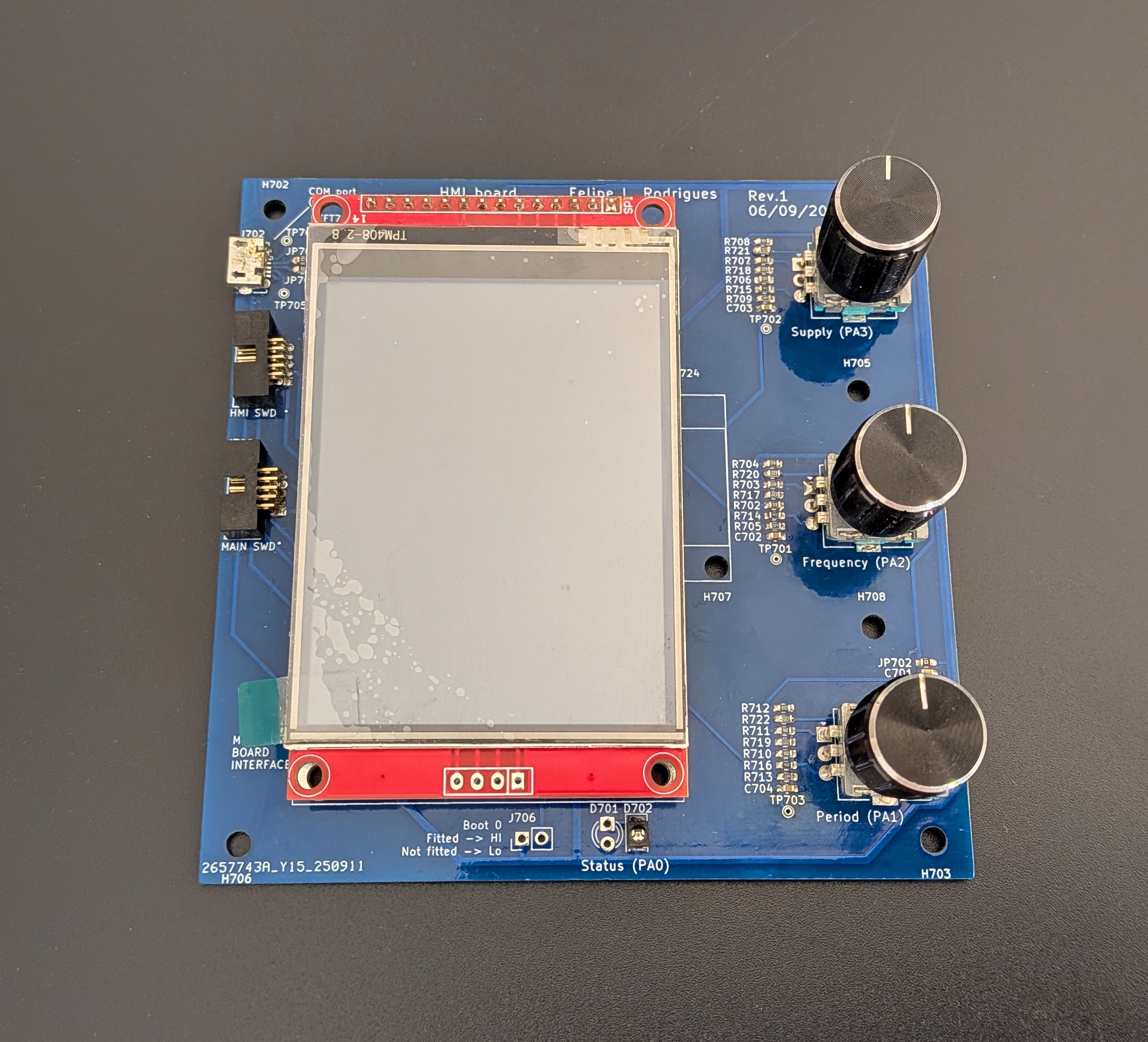
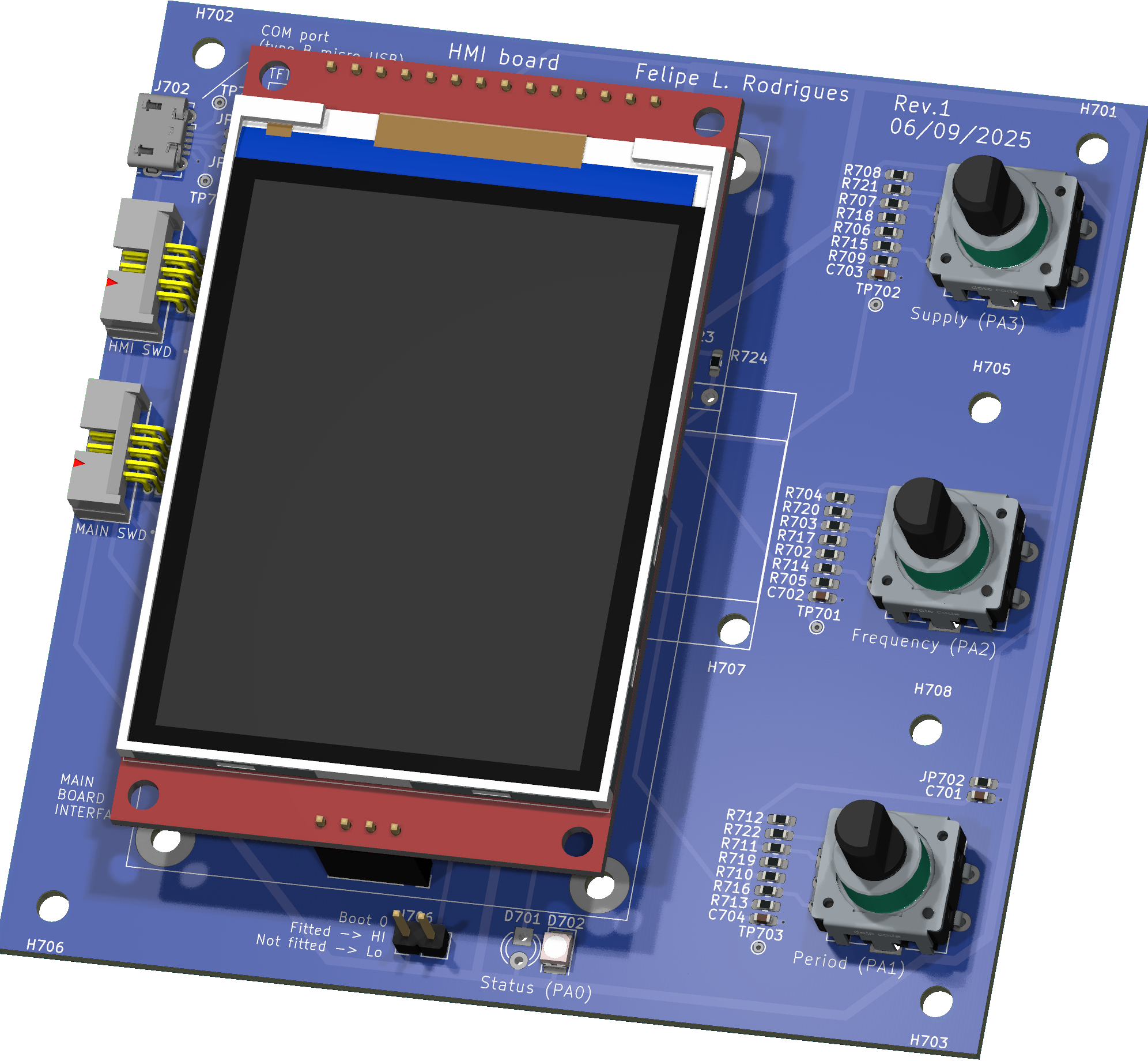
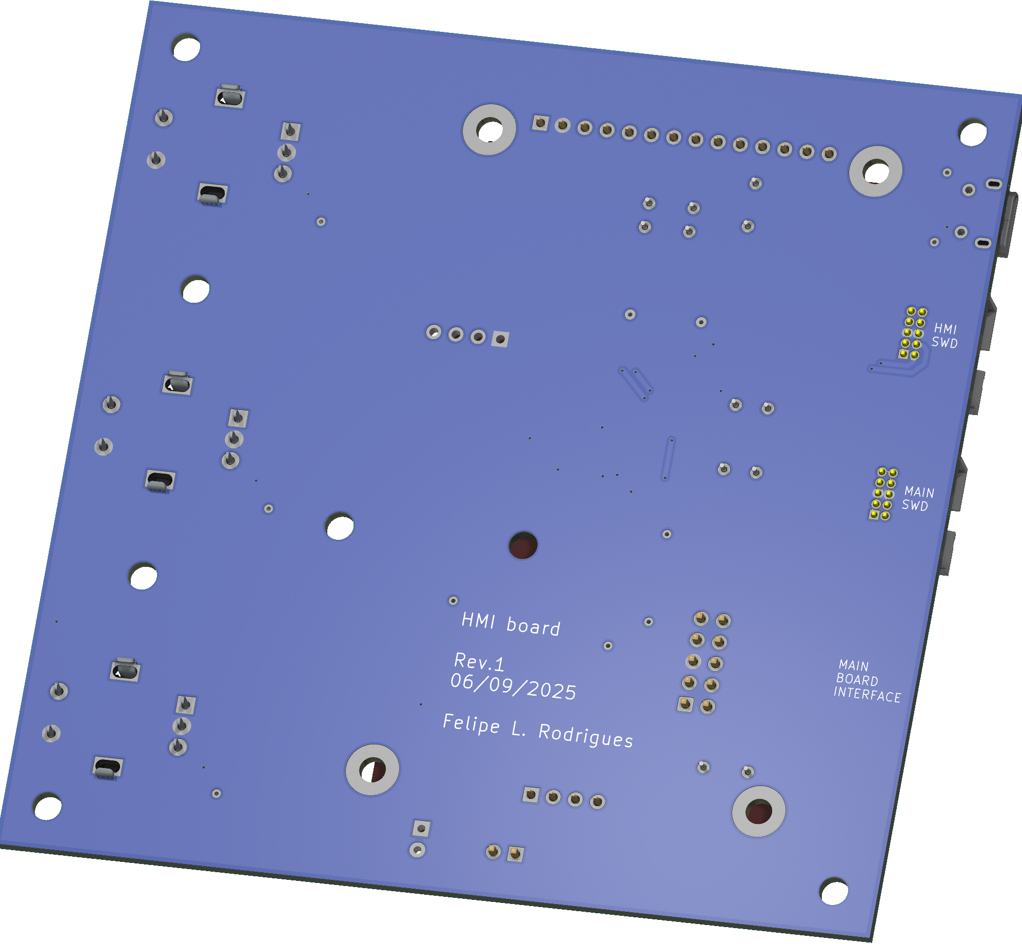
Since my tenage years I spend a great chunk of my spare time on hobby electronics. Back then, much of that time was to build FM transmitters, audio amplifiers and strobe lights. I was always pushing my builds as much as I could, (i.e., extracting pressurised smoke from capacitors!) as an attempt to make the flashes ever brighter. It was somewhat challenging given the limited experience and resources I had at the time, but a lot of fun nonetheless. Life went on, priorities changed and for a long time I did not "play" with strobe lights... until recently, after I bumped into an ebay page of a large XOP-15 bulb and, well, nostalgy happened.
While defining the project scope, I had to decide if I'd use the good old Xenon bulb or move to LEDs, as these have greatly evolved and are ubiquitous nowadays, making their way to commercial strobes (https://www.martin.com/en/products/atomic-3000-led). I have decided to stick to vintage tech, as in my mind this would perhaps bring more interesting power electronics challenges, since the bulb requires a somewhat high bus voltage and can draw very high peak currents when ionised.
So that's what this repo contains: a Xenon-based strobe light, aiming to drive a XOP-15 bulb with up to 1 kV, while controlling the duration and frequency of pulses.
This repository contains KiCad v9 design files for the HMI board of a Xenon-based strobe light system. The system is divided into three separate boards:
Working prototypes exist for both the HMI and main board. This repository covers only the HMI board. The main board is available on its own repo: https://github.com/FLRHW/Strobe_main
The source code is kept on a separate repo: https://github.com/FLRHW/Strobe_HMI_source
As a side project, the boost modules have been reverse engineered with the aim to modify them from non-isolated to isolated. This work is covered under the following repos:
DC bus voltage: 400 V to 1000 V
Flash rate: 0.1 Hz to 100 Hz
Pulse duration: 20 μs to 10 ms
Please note that extremes are not simultaneously achievable. This design relies on storing energy on a capacitor bank to then discharge it into the bulb, hence some time must be reserved for storing that energy. The pulse duration is currently limited in SW to 50 % of the period as a safeguard, but for practical use it must be a much lower percentage.
Also, the output capacitors currently in use are not large enough to reach 10 ms pulse duration - at least not at high output voltages as the bulb current seems to increase non linearly with the bus voltage.
This repository is intended for:
The design files and documentation in this repository are released under the CERN Open Hardware Licence v2 – Permissive (CERN‑OHL‑P‑2.0). SPDX identifier: CERN-OHL-P-2.0 See the LICENSE file for the full legal text and conditions. In short and non‑legal terms, you are free to use, modify, manufacture, and distribute hardware based on these files, provided you respect attribution requirements and the terms in the license.
All product names, logos, and brands eventually mentioned are the property of their respective owners and are not included or licensed here. Any reference to third‑party marks is purely descriptive and does not imply endorsement or affiliation.
│
├─ Computations       # Misc calculations
├─ HTML               # HTML files for generated webpage
├─ Images             # Pictures and renders
│
├─ kibot_resources    # External resources for KiBot
│  ├─ colors          # Color theme for KiCad
│  ├─ fonts           # Fonts used in the project
│  ├─ scripts         # External scripts used with KiBot
│  └─ templates       # Templates for KiBot generated reports
│
├─ kibot_yaml         # KiBot YAML config files
├─ KiRI               # KiRI (PCB diff viewer) files
│
├─ lib                # KiCad footprint and symbol libraries
│  ├─ 3d_models       # Component 3D models
│  ├─ lib_fp          # Footprint libraries
│  └─ lib_sym         # Symbol libraries
│
├─ Logos              # Logos
│
├─ Manufacturing      # Assembly and fabrication documents
│  ├─ Assembly        # Assembly documents (BoM, pos, notes)
│ │| Qty | Value | Footprint | References |
|---|---|---|---|
| 10 | 1k | Resistor_SMD:R_0603_1608Metric_Pad0.98x0.95mm_HandSolder | R702, R703, R704, R706, R707, R708, R710, R711, R712, R726 |
| 9 | 0R | Resistor_SMD:R_0603_1608Metric_Pad0.98x0.95mm_HandSolder | JP702, JP704, JP705, JP706, JP707, JP709, JP711, JP712, JP716 |
| 9 | 100n | Capacitor_SMD:C_0603_1608Metric_Pad1.08x0.95mm_HandSolder | C701, C702, C703, C704, C705, C708, C709, C710, C713 |
| 9 | TestPoint | TestPoint:TestPoint_THTPad_D1.0mm_Drill0.5mm | TP701, TP702, TP703, TP704, TP705, TP706, TP707, TP708, TP709 |
| 8 | MountingHole | MountingHole:MountingHole_3.2mm_M3 | H701, H702, H703, H704, H705, H706, H707, H708 |
| 4 | 0R | Resistor_THT:R_Axial_DIN0204_L3.6mm_D1.6mm_P5.08mm_Horizontal | JP701, JP710, JP713, JP714 |
| 4 | 10k | Resistor_SMD:R_0603_1608Metric_Pad0.98x0.95mm_HandSolder | R701, R725, R727, R728 |
| 3 | 11k | Resistor_SMD:R_0603_1608Metric_Pad0.98x0.95mm_HandSolder | R720, R721, R722 |
| 3 | 220k | Resistor_SMD:R_0603_1608Metric_Pad0.98x0.95mm_HandSolder | R705, R709, R713 |
| 3 | 22k | Resistor_SMD:R_0603_1608Metric_Pad0.98x0.95mm_HandSolder | R717, R718, R719 |
| 3 | 44k | Resistor_SMD:R_0603_1608Metric_Pad0.98x0.95mm_HandSolder | R714, R715, R716 |
| 3 | EncSw | Personal:RotaryEncoderSwitch_Oblong | SW701, SW702, SW703 |
| 2 | 0R | Resistor_THT:R_Axial_DIN0204_L3.6mm_D1.6mm_P7.62mm_Horizontal | JP708, JP715 |
| 2 | 1u | Capacitor_SMD:C_0603_1608Metric_Pad1.08x0.95mm_HandSolder | C706, C707 |
| 2 | 22p | Capacitor_SMD:C_0603_1608Metric_Pad1.08x0.95mm_HandSolder | C711, C712 |
| 2 | 4k7 | Resistor_SMD:R_0603_1608Metric_Pad0.98x0.95mm_HandSolder | R723, R724 |
| 2 | Conn_01x04_Pin | Connector_PinSocket_2.54mm:PinSocket_1x04_P2.54mm_Vertical | J703, J704 |
| 2 | HX JN1.27-2x5 WZ H4.9 | Personal:JN1.27-2x5 WZ H4.9 | J707, J708 |
| 1 | 1050171001 Micro Type B | Personal:USB_Micro-B_Molex-105017-0001 | J702 |
| 1 | 20 MHz | Crystal:Crystal_SMD_3225-4Pin_3.2x2.5mm_HandSoldering | Y701 |
| 1 | 8.12 | Personal:Jumper_mm_L8.12_D1.2_H0.5 | JP703 |
| 1 | Conn_01x14_Pin | Connector_PinSocket_2.54mm:PinSocket_1x14_P2.54mm_Vertical | J705 |
| 1 | Header | Connector_PinHeader_2.54mm:PinHeader_1x02_P2.54mm_Vertical | J706 |
| 1 | LED | LED_THT:LED_D3.0mm | D701 |
| 1 | LED | LED_SMD:LED_PLCC-2_3x2mm_KA | D702 |
| 1 | OLED_128x64_SSD1306 | Personal:OLED_SSD1306_no_pins | OLED701 |
| 1 | STM32G431K8Tx | Package_QFP:LQFP-32_7x7mm_P0.8mm | U701 |
| 1 | TFT_2.8in_320x240 | Personal:TFT_2.8_IN_320x240 | TFT701 |
| 1 | ZHOURI DC3 | Connector_IDC:IDC-Header_2x05_P2.54mm_Horizontal | J701 |
It measures 100 × 100 mm and has 2 copper layers, 1.66 mm thick.
91 parts, built around the RC0603JR-130RP. The full list of its parts is on this page, with links to each part's symbol and footprint where PCBKit's library has them.
From the FLRHW/Strobe_HMI repository on GitHub, at the commit this page was made from: the board is Strobe_HMI.kicad_pcb and its schematic Block diagram.kicad_sch. PCBKit opens the board in the browser, with nothing to install.
Its repository states no licence, so its author keeps all rights: ask FLRHW before reusing the design.
FLRHW/Desk_controller
Standing desk controller - Touch display as HMI and servo motor interface

jes/scamp-cpu
A homebrew 16-bit CPU with a homebrew Unix-like-ish operating system.


sixeight7/VController_v3
Production model of the VController, VC-mini and VC-touch

