2 layers

 Finn254254/orca-one
Proprietary hardware files, schematics, PCB design, documentation and bring-up work for the Orca One V1.0 SBC.
ORCA First Linux Board is an open-source printed circuit board by Finn254254, from the Finn254254/orca-one repository on GitHub. It is a 4-layer board of 73 × 66 mm with 106 parts on 122 nets, routed with 980 tracks and 144 vias.
It is built around the V3S, TPS62160DGK and SRV05-4, with the TPS2041BD among its other parts. Its parts include 45 capacitors, 22 resistors, 8 ICs, 7 diodes and 7 connectors. It belongs with the computers and single-board computers boards of this library.


Hardware design · PCB layout · ORCA OS testing · Bring-up documentation
[!IMPORTANT] Open-source hardware. Orca One V1.0 is released under the CERN Open Hardware Licence Version 2 - Strongly Reciprocal (CERN-OHL-S-2.0). You may study, modify, manufacture, and redistribute the design subject to the license terms. See LICENSE.
[!WARNING] Early hardware revision. Orca One V1.0 has not been manufactured or tested yet. The board is currently waiting on funding before manufacturing.
Orca One is the first test board for Orca servers. The main purpose of the board is to give us our own hardware to start testing ORCA OS on.
The first goal is simple: get our lightweight Linux-based ORCA OS to successfully boot on hardware we designed ourselves. This board is not meant to be a powerful Orca server yet. It is a starting point for testing the hardware and software before moving onto more complicated boards.
| Front | Back |
|---|---|
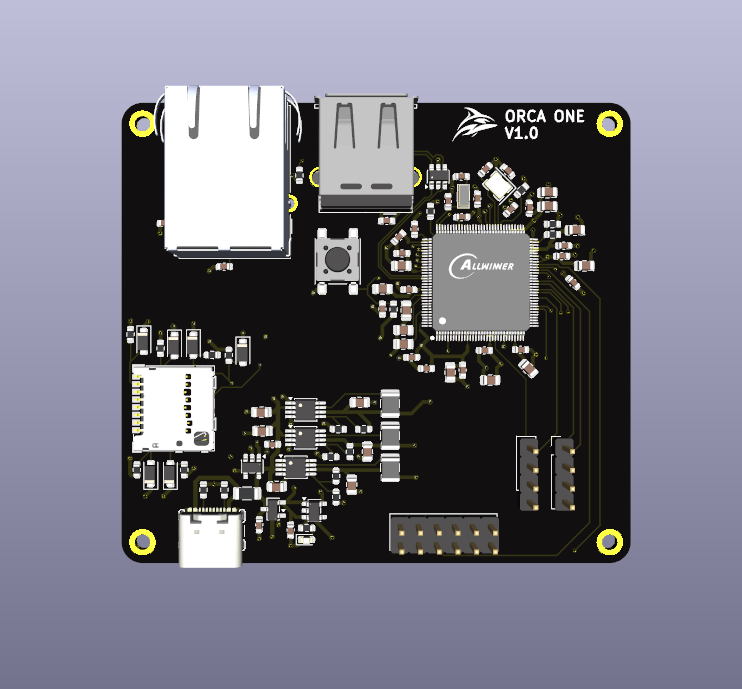 | 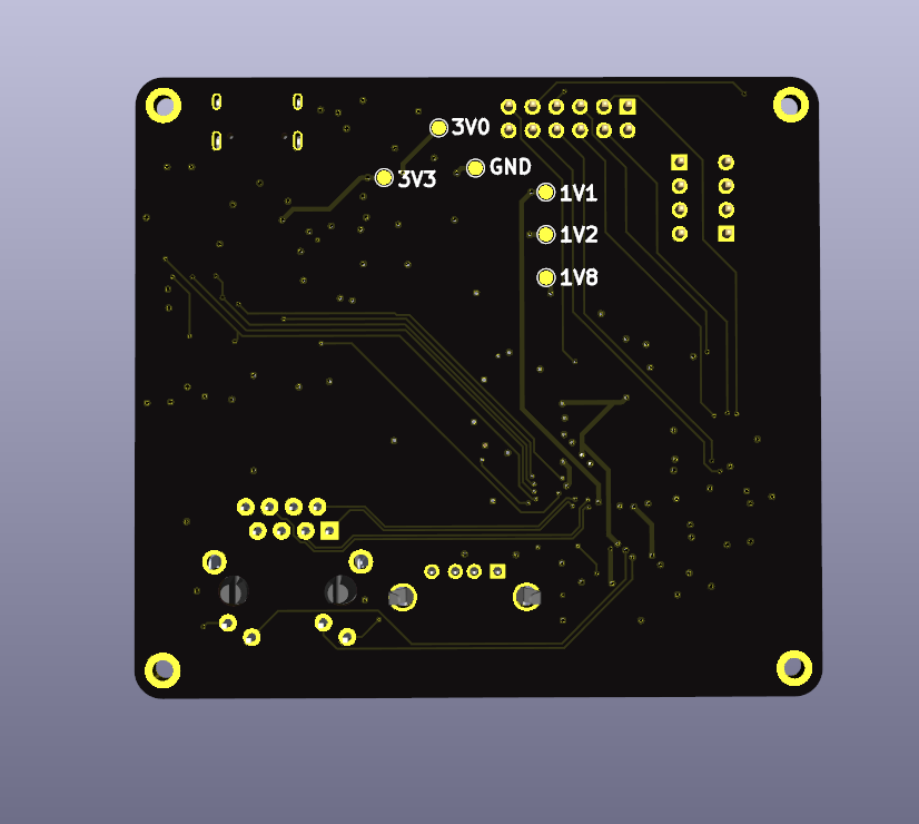 |
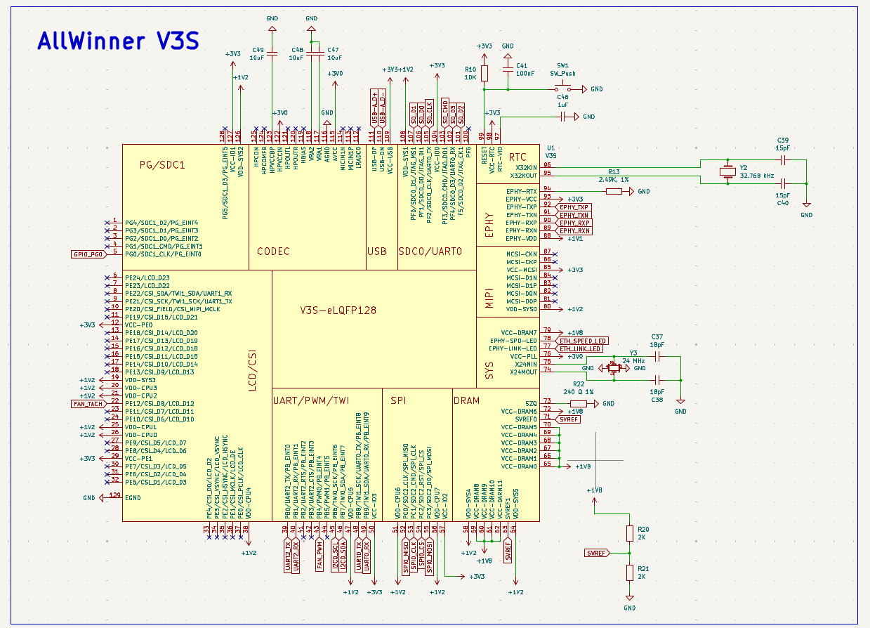
I chose the Allwinner V3s because it is a relatively easy and cheap chip to start with.
One of the biggest reasons was its package. The V3s uses an LQFP package instead of BGA, which makes the PCB easier to design and also makes the chip easier to solder.
It also has integrated RAM instead of requiring external DDR. This means I don't have to route a separate DDR chip for my first Linux board, while I can still get experience designing a board around a Linux-capable SoC.
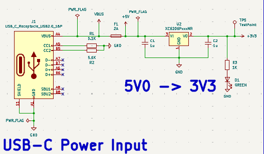
The board is powered using 5 V over USB-C. The USB-C input is configured as a power sink using two 5.1 kΩ resistors on the CC pins.
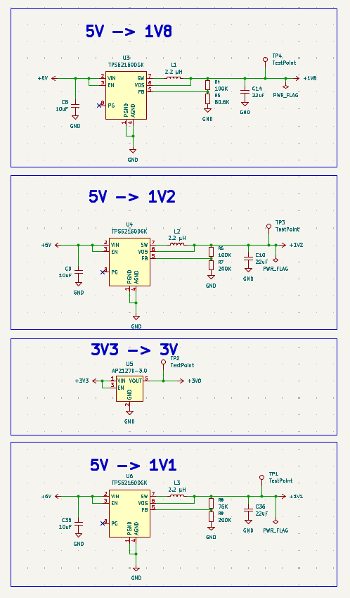
From the 5 V input, the board generates the different voltages required by the V3s and the other parts of the board. These include 3.3 V, 3.0 V, 1.8 V, 1.2 V and 1.1 V.
I decided to design this power system instead of using a premade power module because I wanted to learn and get practice using power regulators and buck converters.
One of the main things I had to learn was how adjustable regulators use a feedback voltage divider. I had to use the regulator equations to work out the resistor values needed to generate the correct output voltages.
This was probably the hardest part of designing the schematic because it involved both understanding the circuit and doing the maths to make sure each rail had the correct voltage.
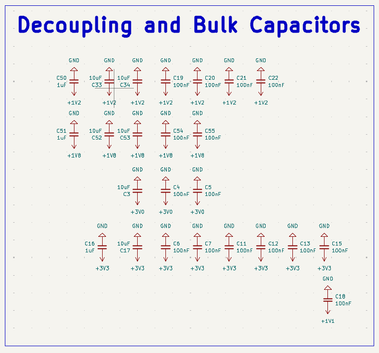
Another part of the power design was adding the decoupling and bulk capacitors for the different rails.
This became one of the hardest parts when I moved onto the PCB layout. I needed to fit the capacitors close to the V3s power pins while still leaving enough room around the SoC to route everything else.
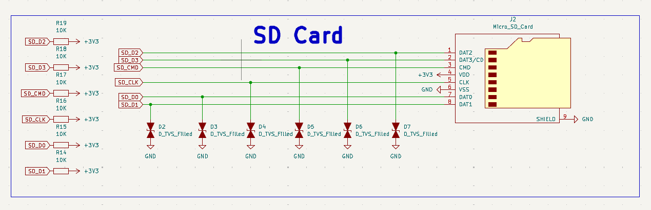
Orca One does not have any other onboard storage, so the MicroSD card is used to store and boot ORCA OS.
The first major software test for the physical board will be seeing if our OS can successfully boot from the MicroSD card.
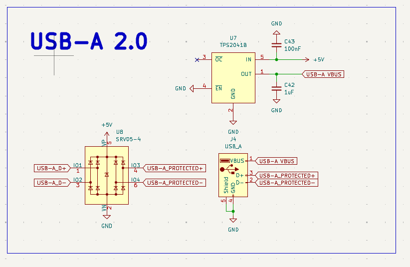
Orca One has a USB-A 2.0 port for connecting USB devices to the board.
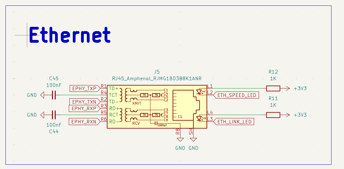
Ethernet was added so Orca One can be managed remotely over the network using SSH.
This means that once ORCA OS is running, I should be able to connect to the board from another computer and manage it without needing a display or keyboard connected directly to Orca One.
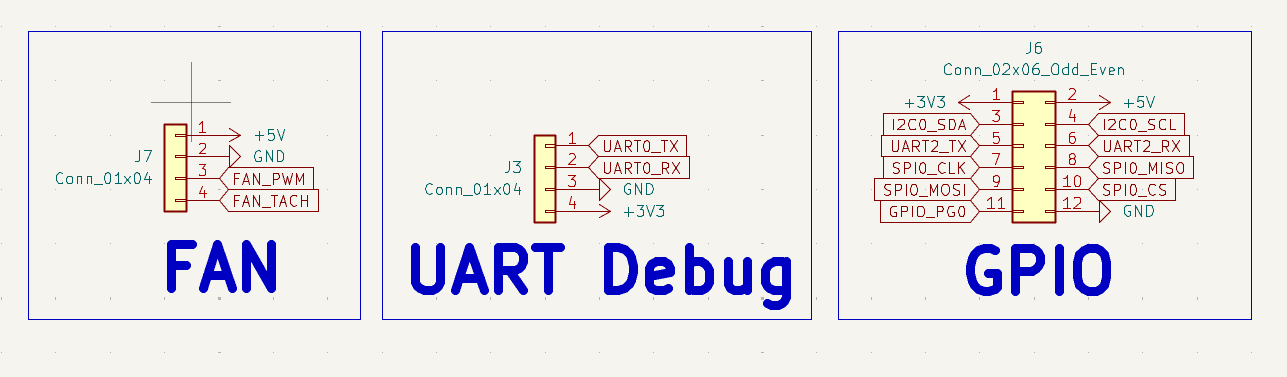
The board also has headers for GPIO, UART and a fan.
UART gives me a way to debug the board, especially during the first boot attempts. The GPIO header exposes connections from the V3s for future testing and expansion, while the fan header gives the board a connection for cooling if needed.
After completing the schematic, I moved onto designing the four-layer PCB.
One of the most difficult parts was placing the decoupling and bulk capacitors close to the SoC while also making sure there was enough room to route the rest of the board.
I also spent a lot of time working on the copper pours. The pours were changed many times during the PCB design as I worked out better ways to shape and position them around the board.
This ended up being one of the biggest things I learned from designing Orca One. Before this project I had much less experience using copper pours, but I now have a much better understanding of how to use and adjust them as part of a PCB layout.
Orca One has given me practice designing a complete board around a Linux-capable SoC instead of only working with individual smaller circuits.
Some of the main things I learned while making the board were:
The biggest thing I learned during the PCB layout was how to use copper pours properly. I changed them several times while designing the board and gradually found better ways to fit them into the layout.
Orca One V1.0 is currently waiting on funding before it can be manufactured.
Because the physical board does not exist yet, none of the hardware has been validated. The next major stage of the project is manufacturing and bring-up.
Once the board has been manufactured and assembled, the first thing I want to find out is whether it powers on correctly.
After that, the main goal is to see if it can successfully boot ORCA OS from the MicroSD card.
Getting the board to power on and boot our own OS will be the first major test of Orca One and will let us start testing the hardware and software together.
The complete editable schematic is included in the KiCad project. Expand a section below for a quick visual tour.
The BOM lists the components needed to assemble one Orca One V1.0 board, including reference designators, footprints, quantities, and component values.
| Item | Cost |
|---|---|
| PCB fabrication | £24.94 |
| Stencil | £2.34 |
| Parts (components) | £36.35 |
The PCB quote was £27.28 including the £2.34 stencil, so the PCB fabrication amount above excludes the stencil to avoid counting it twice. The parts figure is the merchandise total shown in the order summary; shipping (£5.32) is separate, and the displayed merchandise discount was £0.28. These are the quoted costs shown for this order and may change.
Quantities in the BOM are for one board. Check component specifications and availability, and confirm the BOM against the latest schematic before ordering. Orca One V1.0 has not yet been manufactured or tested.
| Path | Contents |
|---|---|
hardware/kicad/ | KiCad 9 project, schematic, and four-layer PCB layout |
hardware/footprints/ | Custom Allwinner V3s LQFP-128 footprint |
bom/ | Bill of materials in CSV and XLSX formats |
manufacturing/ | Gerber/drill archive and component placement data |
images/ | Board photographs, schematic images and renders |
docs/ | Board inspection, boot, and Linux bring-up plans |
software/early-uart/ | Minimal UART0 transmit example for early debugging |
Orca One will be brought up in small, testable stages instead of attempting to boot a complete operating system immediately:
V3s Boot ROM -> U-Boot -> Linux kernel -> minimal root filesystem -> Orca softwareDevelopment images can be written to MicroSD, allowing the bootloader, kernel, device tree, and root filesystem to be updated without modifying the board. UART is the primary early-debug interface.
See the programming and bring-up plan for the staged checklist and the early UART example for a minimal transmit routine.
hardware/kicad/ORCA First Linux Board.kicad_pro.v3s footprint library automatically.The PCB currently references three optional component STEP models from the original designer's local computer, including the V3s processor and Ethernet connector models. They are not included, so KiCad may show those packages without 3D bodies until redistributable models are added.
Review the schematic, PCB, BOM, placement data, and fabrication outputs carefully before ordering or assembling boards.
This is the first hardware revision and has not yet been physically tested. Manufacturing outputs may also become stale as the editable design changes.
Copyright © 2026 Finn Mather.
Orca One V1.0 is open-source hardware licensed under CERN-OHL-S-2.0. You may study, modify, manufacture, and redistribute the design under the terms of the license. See LICENSE for details.
| Qty | Value | Footprint | References |
|---|---|---|---|
| 19 | 100nF | Capacitor_SMD:C_0603_1608Metric | C4, C5, C11, C12, C13, C15, C18, C19, C20, C21, C22, C41, C43, C44, C45, C54 +3 |
| 12 | 10uF | Capacitor_SMD:C_0805_2012Metric | C3, C8, C9, C17, C33, C34, C35, C47, C48, C49, C52, C53 |
| 7 | 10K | Resistor_SMD:R_0603_1608Metric | R10, R14, R15, R16, R17, R18, R19 |
| 6 | D_TVS_Filled | Diode_SMD:D_SOD-123F | D2, D3, D4, D5, D6, D7 |
| 6 | TestPoint | TestPoint:TestPoint_Pad_D1.5mm | TP1, TP1, TP2, TP3, TP4, TP5 |
| 3 | 1K | Resistor_SMD:R_0603_1608Metric | R3, R11, R12 |
| 3 | 1uF | Capacitor_SMD:C_0805_2012Metric | C16, C50, C51 |
| 3 | 2.2 µH | Inductor_SMD:L_1210_3225Metric | L1, L2, L3 |
| 3 | 22uF | Capacitor_SMD:C_0805_2012Metric | C10, C14, C36 |
| 3 | TPS62160DGK | Package_SO:MSOP-8_3x3mm_P0.65mm | U3, U4, U6 |
| 2 | 100K | Resistor_SMD:R_0603_1608Metric | R4, R6 |
| 2 | 15pF | Capacitor_SMD:C_0603_1608Metric | C39, C40 |
| 2 | 18pF | Capacitor_SMD:C_0603_1608Metric | C37, C38 |
| 2 | 1u | Capacitor_SMD:C_0603_1608Metric | C1, C2 |
| 2 | 1uF | Capacitor_SMD:C_0603_1608Metric | C42, C46 |
| 2 | 200K | Resistor_SMD:R_0603_1608Metric | R7, R9 |
| 2 | 2K | Resistor_SMD:R_0603_1608Metric | R20, R21 |
| 2 | 5.1K | Resistor_SMD:R_0603_1608Metric | R1, R2 |
| 2 | Conn_01x04 | Connector_PinHeader_2.54mm:PinHeader_1x04_P2.54mm_Vertical | J3, J7 |
| 1 | 2.49K, 1% | Resistor_SMD:R_0603_1608Metric | R13 |
| 1 | 24 MHz | Crystal:Crystal_SMD_3225-4Pin_3.2x2.5mm | Y3 |
| 1 | 240 Ω 1% | Resistor_SMD:R_0603_1608Metric | R22 |
| 1 | 2A | Fuse:Fuse_1206_3216Metric | F1 |
| 1 | 32.768 kHz | Crystal:Crystal_SMD_3215-2Pin_3.2x1.5mm | Y2 |
| 1 | 75K | Resistor_SMD:R_0603_1608Metric | R8 |
| 1 | 80.6K | Resistor_SMD:R_0603_1608Metric | R5 |
| 1 | AP2127K-3.0 | Package_TO_SOT_SMD:SOT-23-5 | U5 |
| 1 | Conn_02x06_Odd_Even | Connector_PinSocket_2.54mm:PinSocket_2x06_P2.54mm_Vertical | J6 |
| 1 | GREEN | LED_SMD:LED_0603_1608Metric | D1 |
| 1 | Micro_SD_Card | Connector_Card:microSD_HC_Molex_104031-0811 | J2 |
| 1 | RJ45_Amphenol_RJMG1BD3B8K1ANR | Connector_RJ:RJ45_Amphenol_RJMG1BD3B8K1ANR | J5 |
| 1 | SRV05-4 | Package_TO_SOT_SMD:SOT-23-6 | U8 |
| 1 | SW_Push | Button_Switch_SMD:SW_SPST_PTS645Sx43SMTR92 | SW1 |
| 1 | TPS2041B | Package_TO_SOT_SMD:SOT-23-5 | U7 |
| 1 | USB_A | Connector_USB:USB_A_Molex_67643_Horizontal | J4 |
| 1 | USB_C_Receptacle_USB2.0_16P | Connector_USB:USB_C_Receptacle_GCT_USB4105-xx-A_16P_TopMnt_Horizontal | J1 |
| 1 | V3S | v3s:LQFP-128_L14.0-W14.0-P0.40-LS16.0-BL-EP5.0 | U1 |
| 1 | XC6206PxxxMR | Package_TO_SOT_SMD:SOT-23-3 | U2 |
The 102 most common of 106 parts.
It measures 73 × 66 mm and has 4 copper layers, 1.6 mm thick.
106 parts, built around the V3S, TPS62160DGK, SRV05-4 and TPS2041BD. The full list of its parts is on this page, with links to each part's symbol and footprint where PCBKit's library has them.
From the Finn254254/orca-one repository on GitHub, at the commit this page was made from: the board is hardware/kicad/ORCA First Linux Board.kicad_pcb and its schematic hardware/kicad/ORCA First Linux Board.kicad_sch. PCBKit opens the board in the browser, with nothing to install.
Its repository states no licence, so its author keeps all rights: ask Finn254254 before reusing the design.


vrubel/indicator-fun-V3s
"indicator.fun" device implementation on the processor Allwinner V3s

mojo626/iPodClone
This is a clone of an iPod video based on the Allwinner V3s processor


NewTec-GmbH/esp32-can-iot
A ESP32 based interface between CAN-bus and IoT environments.

