2 layers40 × 40 mm

 festlv/isc0901b0-breakout15
Simple breakout board for ISC0901B0 sensor
Isc0901b0-breakout is an open-source printed circuit board by festlv, from the festlv/isc0901b0-breakout repository on GitHub, published under the MIT licence. It is a 2-layer board of 44.9 × 47.2 mm with 60 parts on 61 nets, routed with 435 tracks and 112 vias.
It is built around the TPS61041DBV, TXU0104BQAR and ADP151AUJZ-2.5-R7, with the ADP151AUJZ-3.3-R7, LT3042EMSE#PBF and BSS138PW,115(ES) among its other parts. Its parts include 15 capacitors, 13 resistors, 6 ICs, 4 diodes and 3 transistors. It belongs with the interfaces and adapters and sensors and measurement boards of this library.


ISC0901B0 is 336x256 microbolometer LWIR sensor manufactured by FLIR. Apparently it is being used in Tau2/Vue series camera cores, as well as many other FLIR products. Autoliv NV3 is also based on this sensor, and buying a second-hand, possibly damaged Autoliv NV3 module is probably the cheapest way to obtain such a sensor.
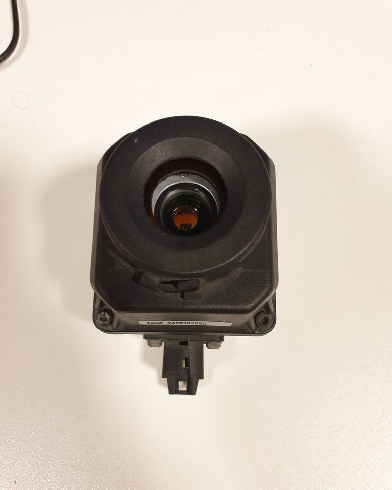
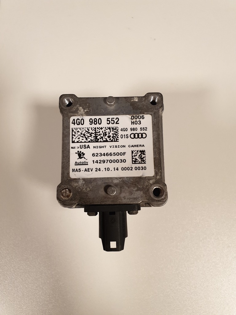
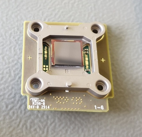
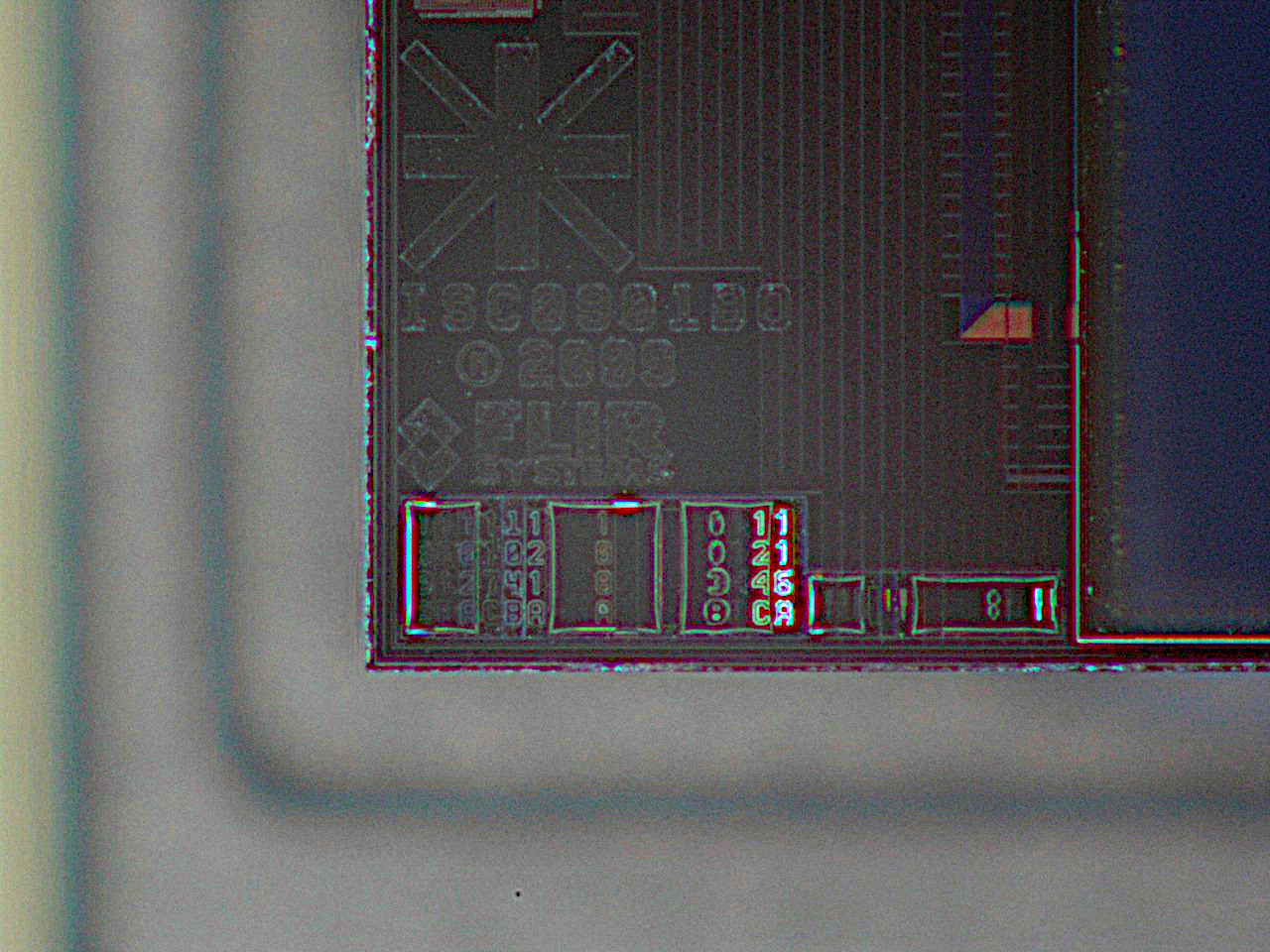
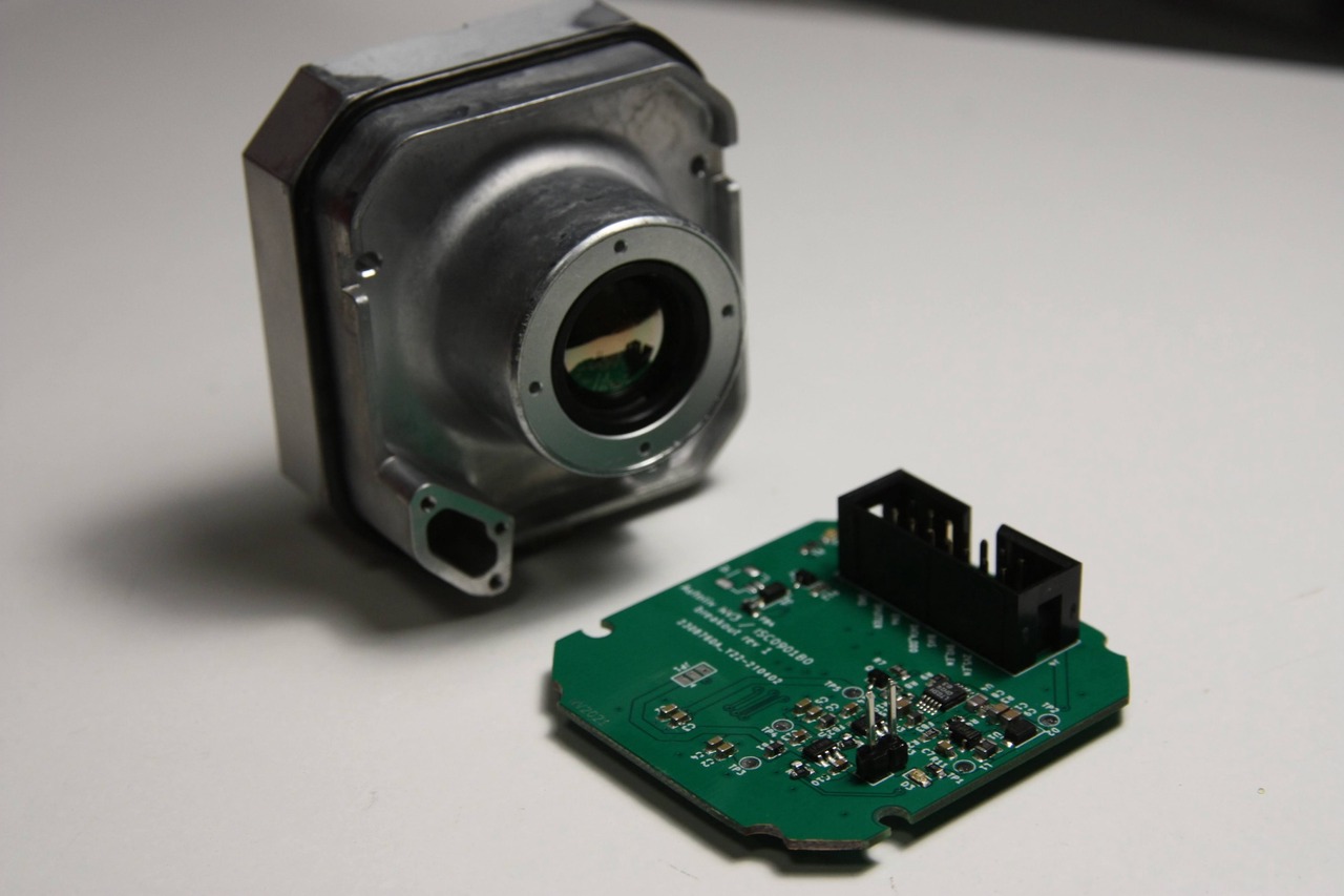
This breakout board connects directly to sensor and provides all the neccessary signals on 14-pin 2.54mm pin header (or IDC header). It also generates the three required power rails: 2.5V for IO signals, 3.3V for core power and switchable 9/11V bias voltage. Breakout board input voltage: 5V. Sensor power consumption (incl. Iq of step-up convertor and LDO losses): approx 60-65mA at 5V input to breakout board.
All the signals described below are single ended, at VCC_IO of the sensor (2.5V in the Autoliv NV3).
-> CLK: clock for the sensor (nominal 73.636MHz for 60Hz). Sampling at other frequencies works, but the image is over/under exposed, as the CMD presumably configures the sensor for particular integration time.
-> CMD: synchronous command to sensor (output on rising edge). Bit order: MSB first.
-> BIAS: synchronous bias data value to sensor. Each bias value is 7-bits long, so there is a value for each pixel. Bit order: LSB first
-> ENA: enable signal to sensor (?). High = sensor enabled, low = sensor disabled.
<- DATA_0, DATA_1: two data bits from sensor (output on falling edge, presumably sampled on rising). Each of the data lines represents a separate pixel. Bit order: LSB first.
Measured without sensor:
BIAS voltage at turn on = 11.0V
After powerup sequence is finished, sensor needs to be enabled. Frame acquisition starts by sending a command preamble that consists of two bytes: [0x3f, 0xc0]. After that, a 20 byte sequence, of which several bytes seem to be specific to each sensor are sent. After predetermined number of clock cycles, sensor starts responding with preamble 0x1555 on both data lines (repeating pattern of zeroes and ones).
One cycle after the sensor has started responding with preamble, bias values should be sent to sensor on the bias line: one 7-bit value for every pixel. The values are specific to each sensor: if a fixed value is sent, part of the pixels may appear to be non-responsive. After preamble (two pixels), sensor sends the subsequent 336 pixels of image data. There is a horizontal blanking period after each line. At the end of the readout (~256 lines), command must be sent again to initate sensor response.
The specific values for command and bias values appear to be stored in the encrypted regions of flash memory on Autoliv NV3. Further research is needed to determine if it's feasible to come up with these values without access to flash memory contents of Autoliv NV3.
rev1 of this breakout board has been verified on Audi 4G0980552. Observed issues:
rev2: fix first 2 problems mentioned above
rev3: Changed the 2.54mm header with 20pin 0.5mm pitch FPC connector for better signal integrity.
| Qty | Value | Footprint | References |
|---|---|---|---|
| 7 | 10uF x 25V | Capacitor_SMD:C_0603_1608Metric | C1, C2, C5, C7, C9, C12, C15 |
| 6 | TestPoint | TestPoint:TestPoint_Pad_D1.5mm | TP1_5V1, TP2_12V1, TP3_3V3, TP4_2V5, TP5_VBIAS1, TP6_GND1 |
| 5 | 1K | Resistor_SMD:R_0603_1608Metric | R5, R6, R9, R11, R13 |
| 4 | 10K | Resistor_SMD:R_0603_1608Metric | R1, R2, R7, R12 |
| 4 | 1uF | Capacitor_SMD:C_0603_1608Metric | C10, C11, C13, C14 |
| 4 | 200R | Inductor_SMD:L_0603_1608Metric | FB1, FB2, FB3, FB4 |
| 4 | 22R | Resistor_SMD:R_Array_Concave_4x0603 | RN1, RN2, RN3, RN4 |
| 3 | 0.1uF x 50V | Capacitor_SMD:C_0603_1608Metric | C3, C4, C6 |
| 3 | BSS138PW,115 | Package_TO_SOT_SMD:SOT-323_SC-70 | Q1, Q2, Q3 |
| 2 | MBR0520LT1 | Diode_SMD:D_SOD-123 | D2, D4 |
| 2 | TXU0104BQA | txu0104bqar:TI_WFNQ-14_BQA | U5, U6 |
| 1 | 100K | Resistor_SMD:R_0603_1608Metric | R3 |
| 1 | 10pF | Capacitor_SMD:C_0603_1608Metric | C8 |
| 1 | 11.5K | Resistor_SMD:R_0603_1608Metric | R4 |
| 1 | 110K | Resistor_SMD:R_0603_1608Metric | R10 |
| 1 | 4.7uH | Inductor_SMD:L_0805_2012Metric | L1 |
| 1 | 499K | Resistor_SMD:R_0603_1608Metric | R8 |
| 1 | 52991-0408 | ics0901b0-breakout:52991-0408 | J2 |
| 1 | ADP151AUJZ-2.5-R7 | Package_TO_SOT_SMD:TSOT-23-5 | U3 |
| 1 | ADP151AUJZ-3.3-R7 | Package_TO_SOT_SMD:TSOT-23-5 | U2 |
| 1 | Conn_01x02 | Connector_JST:JST_SH_BM02B-SRSS-TB_1x02-1MP_P1.00mm_Vertical | J5 |
| 1 | Conn_01x20_MountingPin | X05C2020TZ:X05C2020TZ | J1 |
| 1 | LED_GREEN | Diode_SMD:D_0603_1608Metric | D1 |
| 1 | LED_RED | Diode_SMD:D_0603_1608Metric | D3 |
| 1 | LT3042xMSE | Package_SO:MSOP-10-1EP_3x3mm_P0.5mm_EP1.68x1.88mm | U4 |
| 1 | SolderJumper_3_Open | Jumper:SolderJumper-3_P1.3mm_Open_Pad1.0x1.5mm | JP1 |
| 1 | TPS61041DBV | Package_TO_SOT_SMD:SOT-23-5 | U1 |

Tanki777/telecomlab_fso
The flowgraphs transmit a random source, which are bytes with values between 0 and 255. A random sequence of 30,000 bytes is sent and repeated while the flowgraph is running.

scular-HCC/DualLaserPDHDriver
Dual laster Pound-Dreaver-Hall driver setup. 1550 nm DFBs. Q=10^-5. Less than 20 GHz difference

thewonderidiot/lachesis
Portable, safe readers for Apollo Guidance Computer core rope memory modules

cactorium/UCFBrainStuff
EEG software, alpha stages. Will be opensourced when it's working!

CubeEarthWorld/Open-Binaural-Microphone
Open-source design data for the Xignal Bicarus1 binaural microphone


antmicro/gpu-cluster-backplane
This project contains open hardware design files for a PCB supporting power distribution in a cluster composed of GPUs. This board has been derived from an open source d1600e-psu-breakout created by Antmicro.
It measures 44.9 × 47.2 mm and has 2 copper layers, 1.6 mm thick.
60 parts, built around the TPS61041DBV, TXU0104BQAR, ADP151AUJZ-2.5-R7 and ADP151AUJZ-3.3-R7. The full list of its parts is on this page, with links to each part's symbol and footprint where PCBKit's library has them.
From the festlv/isc0901b0-breakout repository on GitHub, at the commit this page was made from: the board is isc0901b0-breakout.kicad_pcb and its schematic isc0901b0-breakout.kicad_sch. PCBKit opens the board in the browser, with nothing to install.
Its repository publishes it under the MIT licence: you may reuse it on that licence's terms (keep the author's notice, and for a copyleft licence share your changes alike).