2 layers80 × 50 mm
Thermal Camera
Circuit-Digest/MLX90640-Thermal-Camera
An Open Source Thermal Imaging IR camera that you can build yourserlf
66 parts94

 fachat/upet_wifi1
Wifi breakout module for the Micro-PET, Ultra-CPU, and Ulti-PET
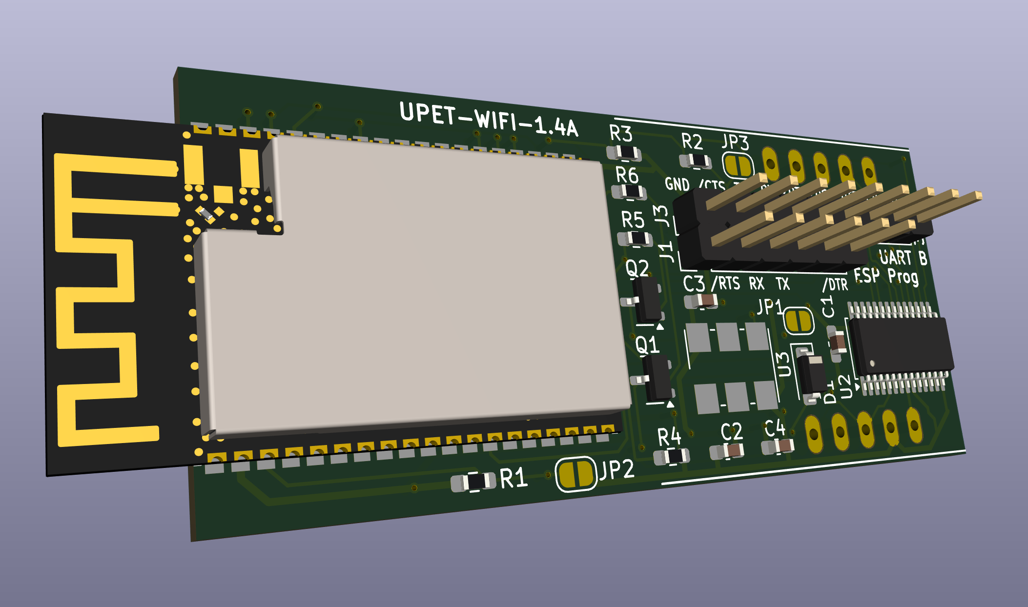
Upet wifi is an open-source printed circuit board by fachat, from the fachat/upet_wifi repository on GitHub. It is a 2-layer board of 56.4 × 25.4 mm with 22 parts on 58 nets, routed with 375 tracks and 51 vias.
It is built around the ESP32-WROVER-E(4MB), SC16IS752IPW and S8050, with the 1N4148W among its other parts. Its parts include 6 resistors, 4 capacitors, 3 ICs, 2 transistors and 2 connectors. It belongs with the radio and wireless boards and the ESP32 boards of this library.


This is part of a larger project with multiple boards, with upet_family as parent repository.
This module implements a Wifi module for the Micro-PET, the Ultra-CPU, and the Ulti-PET. These boards provide an SPI-based breakout connector, which this module plugs in to.
The Wifi-Module used is an ESP32-C3-WROOM-02 module that uses two serial (rs232 on 3.3V TTL level) interfaces - one for firmware updates and logs, the other for the AT commands used to control the communication. To connect to the main board, this breakout board uses a dual-UART SC16IS752 that has an SPI interface to control it.
This repository contains the KiCad schematics and PCB layout, as well as gerber files (gerbers directory). and the interactive BOM (bom directory). Also, in the bom directory is a full XLSX format BOM with manufacturer and Mouser and JLCPCB part numbers, that you can upload to your favourite parts provider.
| Qty | Value | Footprint | References |
|---|---|---|---|
| 3 | 0.1u | Capacitor_SMD:C_0603_1608Metric_Pad1.08x0.95mm_HandSolder | C1, C2, C3 |
| 3 | SolderJumper_2_Open | Jumper:SolderJumper-2_P1.3mm_Open_RoundedPad1.0x1.5mm | JP1, JP2, JP3 |
| 2 | 10k | Resistor_SMD:R_0603_1608Metric_Pad0.98x0.95mm_HandSolder | R1, R4 |
| 2 | 12k | Resistor_SMD:R_0603_1608Metric_Pad0.98x0.95mm_HandSolder | R5, R6 |
| 2 | S8050 | Package_TO_SOT_SMD:SOT-23 | Q1, Q2 |
| 1 | 1.8432 MHz | Oscillator:Oscillator_SMD_IDT_JU6-6_7.0x5.0mm_P2.54mm | U3 |
| 1 | 10u | Capacitor_SMD:C_0603_1608Metric_Pad1.08x0.95mm_HandSolder | C4 |
| 1 | 1N4148W | Diode_SMD:D_SOD-123 | D1 |
| 1 | 1k | Resistor_SMD:R_0603_1608Metric_Pad0.98x0.95mm_HandSolder | R2 |
| 1 | 1k5 | Resistor_SMD:R_0603_1608Metric_Pad0.98x0.95mm_HandSolder | R3 |
| 1 | Conn_01x06 | Connector_PinHeader_2.54mm:PinHeader_1x06_P2.54mm_Vertical | J1 |
| 1 | Conn_01x09 | Connector_PinHeader_2.54mm:PinHeader_1x09_P2.54mm_Vertical | J3 |
| 1 | ESP32-WROVER-E | PCM_Espressif:ESP32-WROVER-E | U4 |
| 1 | SC16IS752IPW | Package_SO:TSSOP-28_4.4x9.7mm_P0.65mm | U2 |
| 1 | uPET NET SPI | UPET-Wifi:UPET_NETSPI | U$1 |
Circuit-Digest/MLX90640-Thermal-Camera
An Open Source Thermal Imaging IR camera that you can build yourserlf

Abhey-05/Thermal-Camera
Thermal Camera A compact, low-cost thermal imaging solution built for diagnostic, repair, and monitoring applications in electronics, industrial safety, and embedded systems.

plantalytix/hardware
Hardware design documents for all plantalytix products. Created using KiCAD version 5 and 6.

Twisted-Fields/acorn-robot-electronics
PCB hardware designs in KICAD for Acorn, the precision farming rover from Twisted Fields.

GSO-soslab/alpha_hardware_release
Alpha electornics schematics and CAD files


SurrealityLabs/sx16is752-breakout
A breakout board for the SC16IS752 I2C/SPI-to-dual-UART IC
It measures 56.4 × 25.4 mm and has 2 copper layers, 1.6 mm thick.
22 parts, built around the ESP32-WROVER-E(4MB), SC16IS752IPW, S8050 and 1N4148W. The full list of its parts is on this page, with links to each part's symbol and footprint where PCBKit's library has them.
From the fachat/upet_wifi repository on GitHub, at the commit this page was made from: the board is Board/UPET-Wifi.kicad_pcb and its schematic Board/UPET-Wifi.kicad_sch. PCBKit opens the board in the browser, with nothing to install.
Its repository states no licence, so its author keeps all rights: ask fachat before reusing the design.