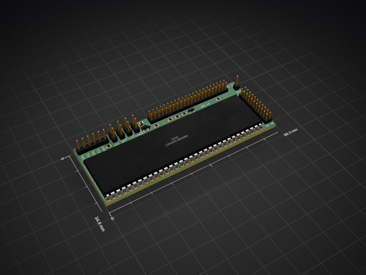
2 layers82.6 × 34.9 mm
A500-ide ram
f1ac0/A500-IDE-RAM
2MB autoconfig Fast SRAM and IDE port expansion for Amiga 500
29 parts10
 f1ac0/A500-IDE-RAM10
2MB autoconfig Fast SRAM and IDE port expansion for Amiga 500
A500-ide ram is an open-source printed circuit board by f1ac0, from the f1ac0/A500-IDE-RAM repository on GitHub. It is a 2-layer board of 88.3 × 34.9 mm with 29 parts on 116 nets, routed with 984 tracks and 84 vias.
It is built around the CY62177ESL-55ZXI, SPX3819M5-L-3-3 and BAT54A. Its parts include 8 connectors, 7 capacitors, 5 resistors, 5 ICs and 1 diode. It belongs with the retro computing and games boards and the FPGA and CPLD boards of this library.


This is an expansion for Amiga 500 and plus providing 2MB Fast SRAM and one IDE port. I believe the two things that the A500 lacks the most are probably a hard drive, and Fast RAM.
The RAM is configured by default as 2MB Fast autoconfig (in the 200000-9FFFFF space), and it can be turned into a 1.5MB (fast) RAM in ranger space (C00000-D7FFFF) together with 512KB MapROM. This mode is targeted for owners of plus or expanded rev8a who want to play old picky games from floppies. The modes and maprom can be configured by maintaining the reset from 3 to 10s or by using the provided Amiga software.
Facts about this project :
Thanks Guys :
This is a hobbyist project, it comes with no warranty and no support. Also remember that the Amiga machines are about 30 years old and may fail because of such hardware expansions.
I publish my work under the CC-BY-NC-SA license. The content of this repository is the result of weeks of work, requiring investment in tools, parts, prototypes, and risky tests on his own equipment. For this reason the author does not want third parties to sell products and keep all the profit, usually without even offering support to their customers. If you see people selling this without the consent of the author, don't buy from them.
If you find it useful and want to reward my hard work : I am always looking for Amiga/Amstrad CPC hardware to repair and hack, please contact me.
Components are SMD, and have thin pin pitch. You need to know what you are doing.
Check for shorts at least between 5V, 3.3V, and GND traces before applying power !
The programming port does not need to be soldered since it needs to be programmed just once : you can just hold it in place during the few seconds required for programming.
CPLD code is generated and built into xsvf using Xilinx ISE 14.7 IDE then iMPACT. There are configuration defines for RAM type and LED/config_pins selection, choose the ones you need. The "Process Properties" of the Fitting step are tweaked :
There are several methods to program the XC95144XL, I personally use xsvfduino. I advise you program it when unplugged from the motherboard, otherwise make sure to power it from the motherboard and not your programmer or it might burn trying to power the whole system.
Maintaining the reset for a few seconds will allow you to :
You may use the provided FLACOntrol software to control the board from your OS. It exists in several flavours, with classic or unix-like command line arguments, or silent with minimal text output.
It provides a MapROM function that writes a 256K or 512K ROM image to F80000-FFFFFF. It also communicates with this expansion using a control register byte at $00E9Cxxx :
To activate Ranger RAM with MapROM ; this will take effect at next reboot :
FLACOntrol -1To map the internal ROM (might speed up the system) :
FLACOntrol -iOr a different ROM from file, 256K and 512K are supported :
FLACOntrol -f Files:path/kickstart-image-not-swapped-nor-split.romIt will revert to the hardware ROM at next power cycle or with :
FLACOntrol -xAnd revert to the full autoconfig RAM and reboot immediately to take effect :
FLACOntrol -0 -rTo use the MapROM function more extensively, you may compile the CPLD firmware to provide MapROM by default, then add the following line to your startup-sequence. The -r flag tells the software to reboot the system after the new ROM is loaded, then during next reboot the software will exit since MapROM is already active, and your system will finish to boot with the new ROM :
FLACOntrol -f Files:path/kickstart-image-not-swapped-nor-split.rom -r| Qty | Value | Footprint | References |
|---|---|---|---|
| 5 | 100n | Capacitor_SMD:C_0805_2012Metric | C1, C3, C4, C5, C7 |
| 3 | 10k | Resistor_SMD:R_0805_2012Metric | R1, R2, R3 |
| 2 | 10u | Capacitor_SMD:C_0805_2012Metric | C2, C6 |
| 2 | 4k7 | Resistor_SMD:R_0805_2012Metric | R4, R5 |
| 1 | 330 | Resistor_SMD:R_0805_2012Metric | RLED1 |
| 1 | 68000D socket | Sassa:DIP-64_W22.86mm_BigPads1.4 | U1 |
| 1 | BAT54A | Package_TO_SOT_SMD:SOT-23 | D1 |
| 1 | CY62177ESL-55ZXI | Package_SO:TSOP-I-48_18.4x12mm_P0.5mm | U4 |
| 1 | Clock | Connector_PinHeader_2.00mm:PinHeader_2x11_P2.00mm_Vertical | J8 |
| 1 | Fiducial | Sassa:CC_BY_NC_SA_square_silkscreen | FID1 |
| 1 | IDE | Connector_PinHeader_2.00mm:PinHeader_2x22_P2.00mm_Vertical | J7 |
| 1 | INT2OVR | Connector_PinHeader_2.54mm:PinHeader_1x02_P2.54mm_Vertical | J4 |
| 1 | INT6 | Connector_PinHeader_2.54mm:PinHeader_1x01_P2.54mm_Vertical | J5 |
| 1 | JTAG | Connector_PinHeader_2.54mm:PinHeader_1x06_P2.54mm_Vertical | J6 |
| 1 | LED | Connector_PinHeader_2.54mm:PinHeader_1x02_P2.54mm_Vertical | J2 |
| 1 | OPT | Connector_PinHeader_2.54mm:PinHeader_1x02_P2.54mm_Vertical | J3 |
| 1 | RAM2 CE | TestPoint:TestPoint_Pad_D1.0mm | TP1 |
| 1 | SPX3819M5-L-3-3 | Package_TO_SOT_SMD:SOT-23-5 | U3 |
| 1 | XC6206PxxxMR | Sassa:SOT-23 | U13 |
| 1 | XC95144XL-TQ100 | Package_QFP:TQFP-100_14x14mm_P0.5mm | U2 |
| 1 | power | Connector_PinHeader_2.54mm:PinHeader_1x02_P2.54mm_Vertical | J1 |
f1ac0/A500-IDE-RAM
2MB autoconfig Fast SRAM and IDE port expansion for Amiga 500


f1ac0/A1200FaStRamExpansion
Up to 9.5MB trapdoor Fast RAM for Amiga 1200, with 512KB mapROM


MycroftAI/hardware-mycroft-mark-II
Mycroft's Mark II Rpi mechanical, electrical and industrial designs


marsairforce/breakout_boards
Small circuit boards to assist with breadboard prototyping with SMD packages.

mnemocron/FHNW-Pro4E-FS19T8-3DPrinterBoard-STM32
Marlin 2.0 compatible 3D printer board based on STM32F103 (KiCad)

95lux/aware01
Aarebot is a dynamic realtime sampler built as a Eurorack module. At its core is a stereo tape-style engine with a hot-swapping record/playback buffer - this enables to record and play simultaneously.
It measures 88.3 × 34.9 mm and has 2 copper layers, 1.6 mm thick.
29 parts, built around the CY62177ESL-55ZXI, SPX3819M5-L-3-3 and BAT54A. The full list of its parts is on this page, with links to each part's symbol and footprint where PCBKit's library has them.
From the f1ac0/A500-IDE-RAM repository on GitHub, at the commit this page was made from: the board is Clockport/KiCAD/a500-ide-ram.kicad_pcb and its schematic Clockport/KiCAD/a500-ide-ram.kicad_sch. PCBKit opens the board in the browser, with nothing to install.
Its repository states no licence, so its author keeps all rights: ask f1ac0 before reusing the design.