2 layers65.4 × 63 mm
LoRa Gateway E32
ezcGman/lora-gateway
Gateway to create a bridge between your LoRa devices and Wi-Fi or Ethernet. Also comes with ready-to-use code to drop everything into your MQTT server!
12 parts39

 ezcGman/lora-gateway39
Gateway to create a bridge between your LoRa devices and Wi-Fi or Ethernet. Also comes with ready-to-use code to drop everything into your MQTT server!
LoRa Gateway E220 is an open-source printed circuit board by ezcGman, from the ezcGman/lora-gateway repository on GitHub. It is a 2-layer board of 65.4 × 63 mm with 15 parts on 37 nets, routed with 98 tracks and 41 vias.
It is built around the M2.5. Its parts include 3 resistors, 3 ICs, 2 capacitors, 1 connector and 1 fuse. It belongs with the radio and wireless and interfaces and adapters boards and the ESP32 boards of this library.
This repository gives you everything you need to easily build (it's a DIY project!) a great quality LoRa-To-MQTT gateway, based on EByte LoRa modules and an ESP32 and works either with Wi-Fi or Ethernet, running off 5V. There are two different versions of the gateway, details on those versions and which you should pick down below:
For giving the board Ethernet capability, I'm using the QuinLED ESP32 Ethernet Hat. Of course, It's natural that I should have also used a QuinLed ESP32, but I had a few spare standard ESP32 devboards laying around with no use for, so I designed the board around these. But that said, I might one day design a version completely based on the QuinLED-ESP32.
To easily switch between Wi-FI and Ethernet, there's a jumper on the board to do just that. This even works with the board powered; no need to cut power.
Again, this is a DIY project! So first off, you need a few soldering skills and I highly recommend either a SMD hot plate or hot air gun to solder the Ebyte E32 module. Its very very hard to solder it with just an iron!
So you want to get the PCBs printed at a PCB prototype factory of your choice, like JLCPCB or PCBWay. I've included the Gerber files for both in the respectiv folder. If you want to use a different service provider, you need to check if they may accept these gerbers or generate them yourself.
I also highly recommend that you order this PCB with a stencil, otherwise you gonna have a hard time putting the paste on the pads of the EByte module!
Each PCB folder has an iBOM HTML file which gives you nice soldering instructions / overview, find it in the ibom folder in each versions folder. When you've soldered the board, simply wire it up with a 5V power source and there you go! It consumes less than 200mA, so you can easily use an old 500mA, 1A (or higher) phone charger for it.
Source is available in the src folder. Download Arduino IDE, check the config.h file and replace the placeholders with your settings, compile and upload to the ESP32. That should be it and the gateway should pop up in your MQTT server and send health check messages every 5 seconds.
How you can now have your sensors and boards have LoRa messages sent to it can be found in the "Source Code / Software" section below.
Which one should you pick? That's pretty easy and defined by one factor:
You need to choose between those, as the EByte modules that use serial communication can't communicate with the RFM95 modules, although they use the same Semtech SX1276 LoRa chip. That's because the EByte serial-operated modules also have a litte MCU onboard that already does its own "stuff" / protocol when sending messages via LoRa. So you don't talk directly to the Semtech chip, but that little MCU instead. One would need to understand how exactly that works to read these messages with a LoRa modules that uses direct SPI communication to the Semtech chip (like the specific E32 module I use, or the RFM95) to make them work with each other.
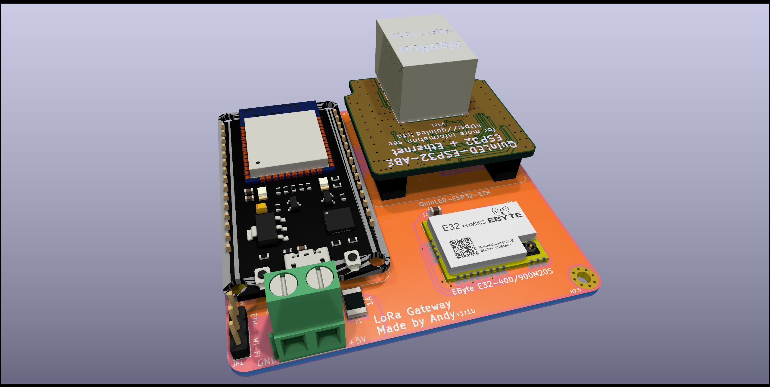 This version is based on the EByte E32-400M20S or E32-900M20S, which offers direct serial communicaton to the Semtech SX1276. At the time of last research (begin of 2022), this is the only E-Byte module that works on this PCB, so you can't use any other that uses serial communication: They won't fit on the board / have a different pinout! Pick the right one for your region (tl;dr: 400 for US/Asia, 900 for Europe).
The module is not in the BOM CSV file, you need to get it off AliExpress:
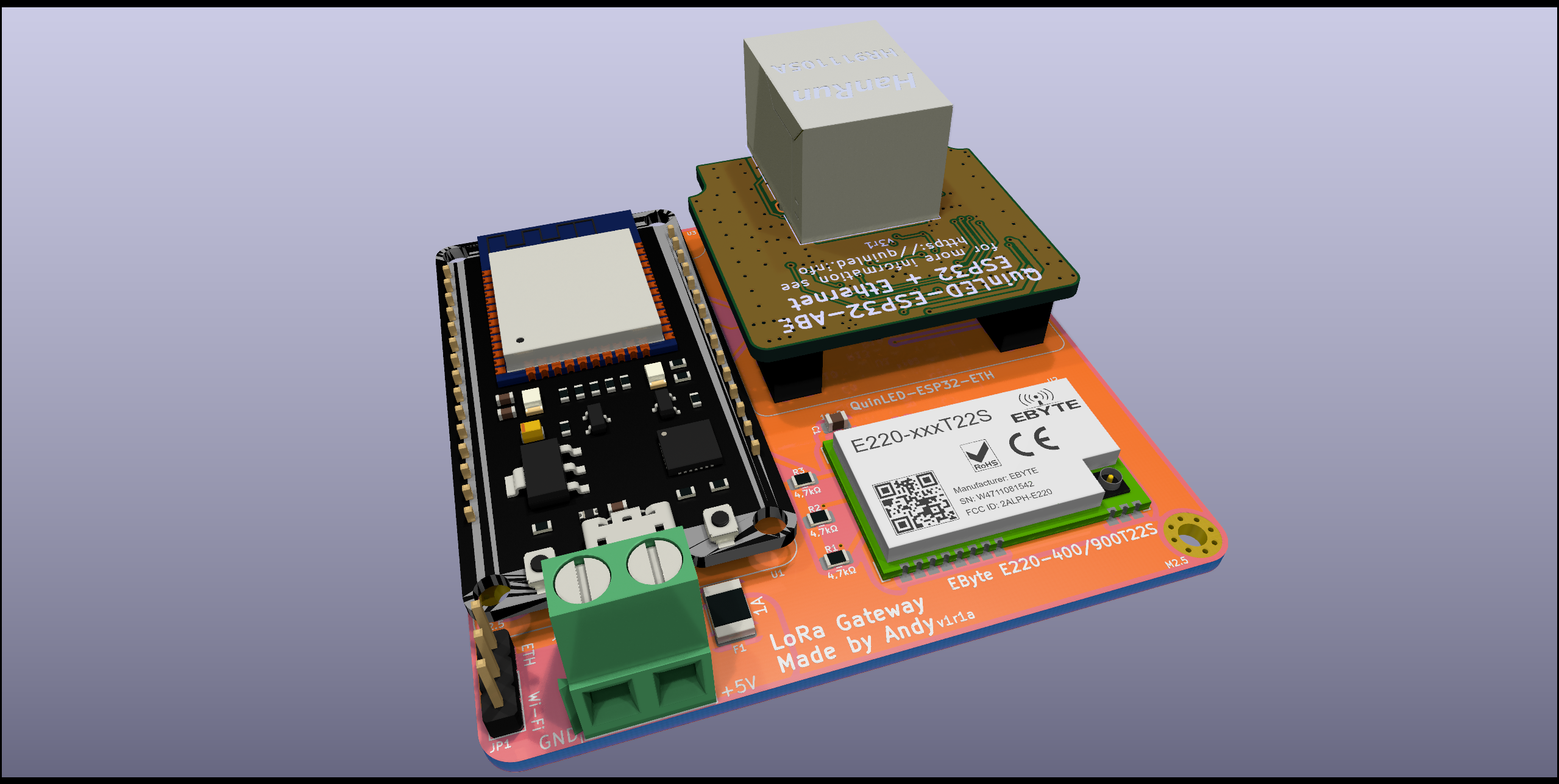 If you usually work in the EByte ecosystem with its serial interfaced modules, this board is for you. However I've not done a port of my E32 based software for this board. And I'm actually not planning to do so, as I personally use the E32 version. But you're welcome to port it using Renzo Mischiantis Arduino library.
The module is not in the BOM CSV file, you need to get it off AliExpress:
The software I've developed for this is meant to be easily extensible without touching the actual logic of the gateway itself, but instead adding a little piece of code to a separate file.
Take a look at lora-ids.h. This file is meant to be shared between this gateway and all sensors you develop. It has a list of different message types and you can easily add your own. E.g., it has a "mailbox" type which defines a few properties a mailbox would send. This makes it very easy to read and process this messages and create topics in your MQTT server which you then can listen to. There's also a "custom" type which basically has free text and is maybe good for debugging.
Feel free to add your own types in this file. You will need to add two things:
#define LORA_MESSAGE_ID_CUSTOM 0x0struct LoRaMessageCustom : LoRaBaseThe subject where a message falls into is built out of the gateway ID, device ID and message ID. So for the following example we assume that:
0xA and name mailbox-sensor has sentLORA_MESSAGE_ID_MAILBOX and0x1 and name lora-gateway-e32 receives it.So let's first take the mailbox message type as an example. It define these properties:
Additionally, it defines its own name (and with that: The parent for these properties):
String getMqttTopicName() { return "mailbox"; }So whenever the gateway will receive a message of this type, it will read the properties from it and drop them into these topics:
???/messages/mailbox/duration???/messages/mailbox/distance???/messages/mailbox/humidity???/messages/mailbox/temperatureBut where does the /messages/ part come form and what is ???/. That's easy: Easy device / sensor you develop should also be registered in lora-ids.h. At the very top, there is list of devices, each with:
The gateway will sort all messages it receives by device and prefixes it with that device name, plus sorts all messages under a messages topic to allow the device have other topics next to the actual messages. This allows you to listen to specific fields/values of specific message types from a specific device!
So we now know this:
???/mailbox-sensor/messages/mailbox/duration???/mailbox-sensor/messages/mailbox/distance???/mailbox-sensor/messages/mailbox/humidity???/mailbox-sensor/messages/mailbox/temperatureThe last missing piece is the gateway that receives the messages. It's also defined as a device, so it also has a name, so we can easily construct the full topic name for our example:
lora-gateway-e32/devices/mailbox-sensor/messages/mailbox/durationlora-gateway-e32/devices/mailbox-sensor/messages/mailbox/distancelora-gateway-e32/devices/mailbox-sensor/messages/mailbox/humiditylora-gateway-e32/devices/mailbox-sensor/messages/mailbox/temperatureNow you can easily:
LORA_DEVICE_IDS with an ID and nameTake a look at the sendLoRaMessage function:
bool sendLoRaMessage(byte messageID, LoRaBase *loRaMessage, byte recipientId = 0, byte senderId = 0)
It expects us to give it:
We can also optionally specify:
LORA_GATEWAY_IDLORA_DEVICE_ID, if not specifiedSo in your code, simply create an instance of the message ID you want to send and pass it to sendLoRaMessage:
LoRaMessageMailbox *loRaMessage = new LoRaMessageMailbox;
loRaMessage->duration = duration;
loRaMessage->distance = distance;
loRaMessage->humidity = humidity;
loRaMessage->temperature = temperature;

sendLoRaMessage(LORA_MESSAGE_ID_MAILBOX, loRaMessage);
And that's it :)
For this we take a look at how the actual message is constructed that is sent via LoRa. The basic idea is stolen from the Arduino-LoRa library, which uses singly bytes to identify senders, receivers, etc.
Looking at a single message:
|. So taking the mailbox message example from above, the value for the message could look like this: 12345|3.56|44.55|27.4| Qty | Value | Footprint | References |
|---|---|---|---|
| 4 | M2.5 | MountingHole:MountingHole_2.5mm_Pad_Via | H1, H2, H3, H4 |
| 3 | 4,7kΩ | Resistor_SMD:R_0805_2012Metric | R1, R2, R3 |
| 2 | 10µF | Capacitor_SMD:C_0805_2012Metric | C1, C2 |
| 1 | 1A | Fuse:Fuse_1812_4532Metric | F1 |
| 1 | Conn_01x02 | TerminalBlock_Phoenix:TerminalBlock_Phoenix_MKDS-1,5-2-5.08_1x02_P5.08mm_Horizontal | J1 |
| 1 | EByte E220-400/900T22S | Andys-Footprints:E-Byte-E220-xxxT22S | U2 |
| 1 | ESP32_DevKit_V1_DOIT | Andys-Footprints:esp32_devkit_v1_doit-less-silkscreen | U1 |
| 1 | Jumper_3_Open | Connector_PinHeader_2.54mm:PinHeader_1x03_P2.54mm_Vertical | JP1 |
| 1 | QuinLED-ESP32-ETH-Hat | QuinLED:QuinLED-ESP32-ETH-Hat | U3 |
ezcGman/lora-gateway
Gateway to create a bridge between your LoRa devices and Wi-Fi or Ethernet. Also comes with ready-to-use code to drop everything into your MQTT server!

Spirit532/studio_mic
A simple, easy to build preamplifier for any true condenser capsule, to make a condenser microphone


gmcn42/clumsyMIDI
A THT-only Raspberry Pi expansion board containing a MIDI interface, DAC, and OLED display

DvidMakesThings/HW_PDNode-600-Pro
The PDNode-600 is a professional-grade, 600W USB Power Delivery Unit designed specifically for compact 10-inch rack systems, targeting embedded developers, homelab enthusiasts, test benches, and smart infrastructure.


Zebra-Rodeo/marelleo
Une boîte qui raconte une histoire quand on pose une figurine dessus. Boîtier, carte, micrologiciel et doc pour la refaire.

dsanchezseco/punk75
Ortholinear keyboard with 75 keys and all components through hole
It measures 65.4 × 63 mm and has 2 copper layers, 1.6 mm thick.
15 parts, built around the M2.5. The full list of its parts is on this page, with links to each part's symbol and footprint where PCBKit's library has them.
From the ezcGman/lora-gateway repository on GitHub, at the commit this page was made from: the board is pcbs/LoRa-Gateway-E220/LoRa-Gateway-E220.kicad_pcb and its schematic pcbs/LoRa-Gateway-E220/LoRa-Gateway-E220.kicad_sch. PCBKit opens the board in the browser, with nothing to install.
Its repository states no licence, so its author keeps all rights: ask ezcGman before reusing the design.