4 layers60 × 94 mm
DaisySeedPedal125b
bkshepherd/DaisySeedProjects
A collection of hardware and software projects based around the Electro-Smith Daisy Seed
80 parts559MIT

 Spirit532/studio_mic150
A simple, easy to build preamplifier for any true condenser capsule, to make a condenser microphone
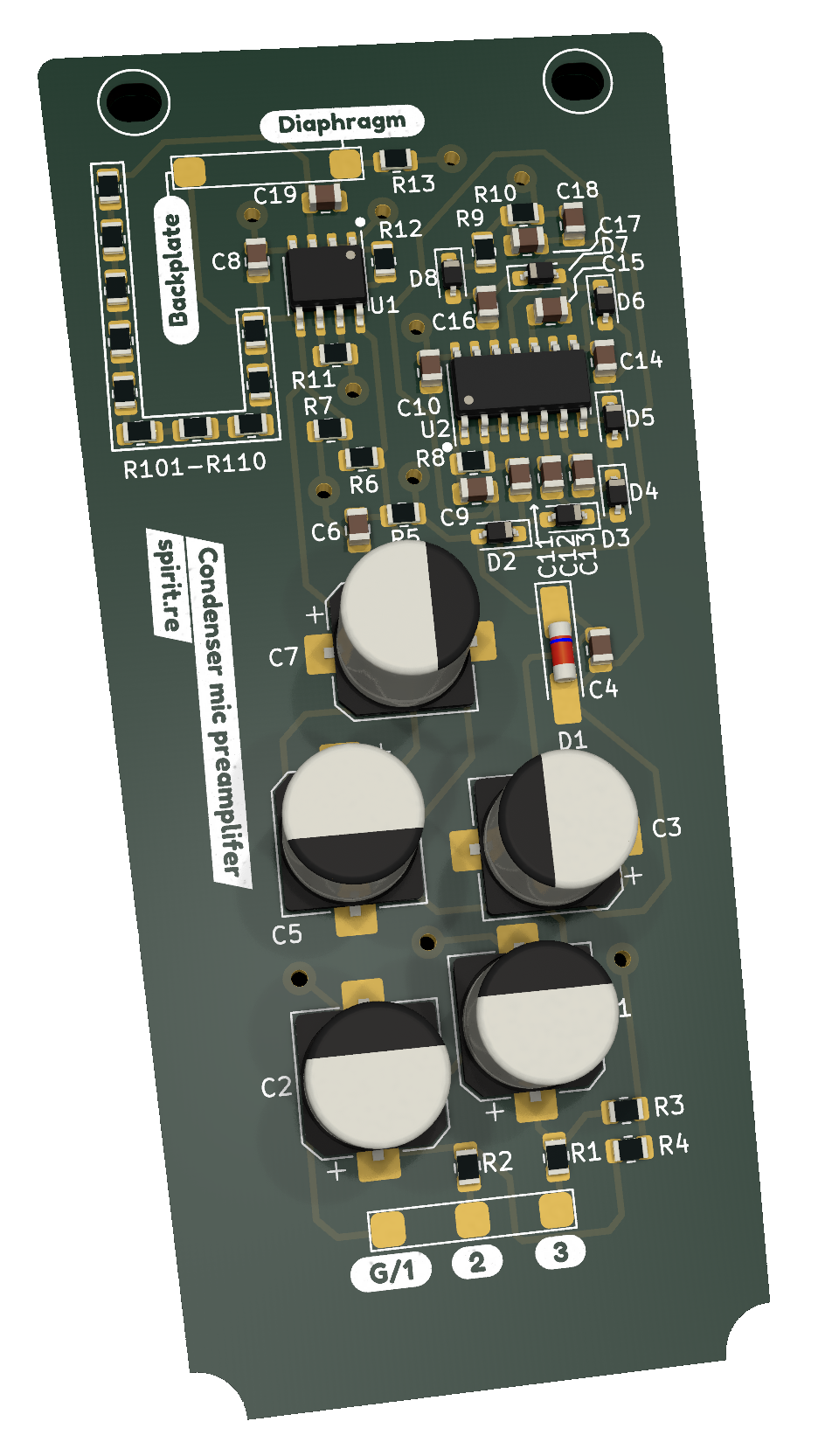
Studio mic is an open-source printed circuit board by Spirit532, from the Spirit532/studio_mic repository on GitHub, published under the MIT licence. It is a 2-layer board of 40.9 × 85 mm with 63 parts on 38 nets, routed with 295 tracks and 12 vias.
It is built around the OPA1652AID, HEF40106BT and 1N4148WS, with the M2.5 among its other parts. Its parts include 23 resistors, 19 capacitors, 8 diodes, 2 ICs and 1 connector. It belongs with the audio and music boards of this library.


I needed a good quality microphone, but all of the options available were either a bit pricy or just not really good in performance, so I decided to build my own.
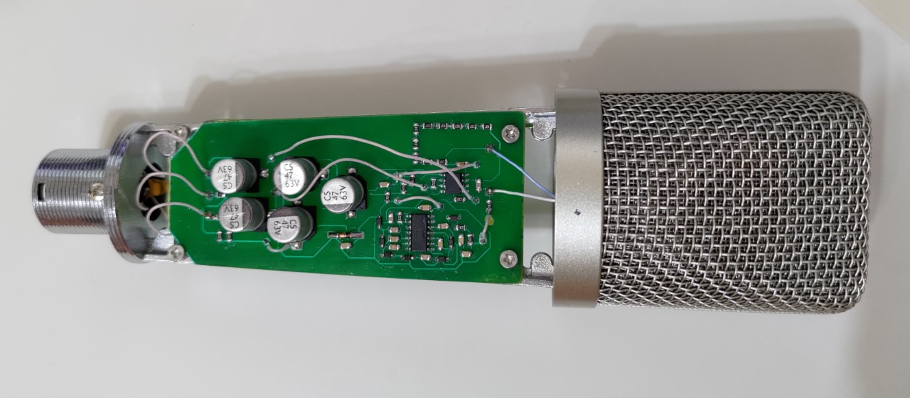
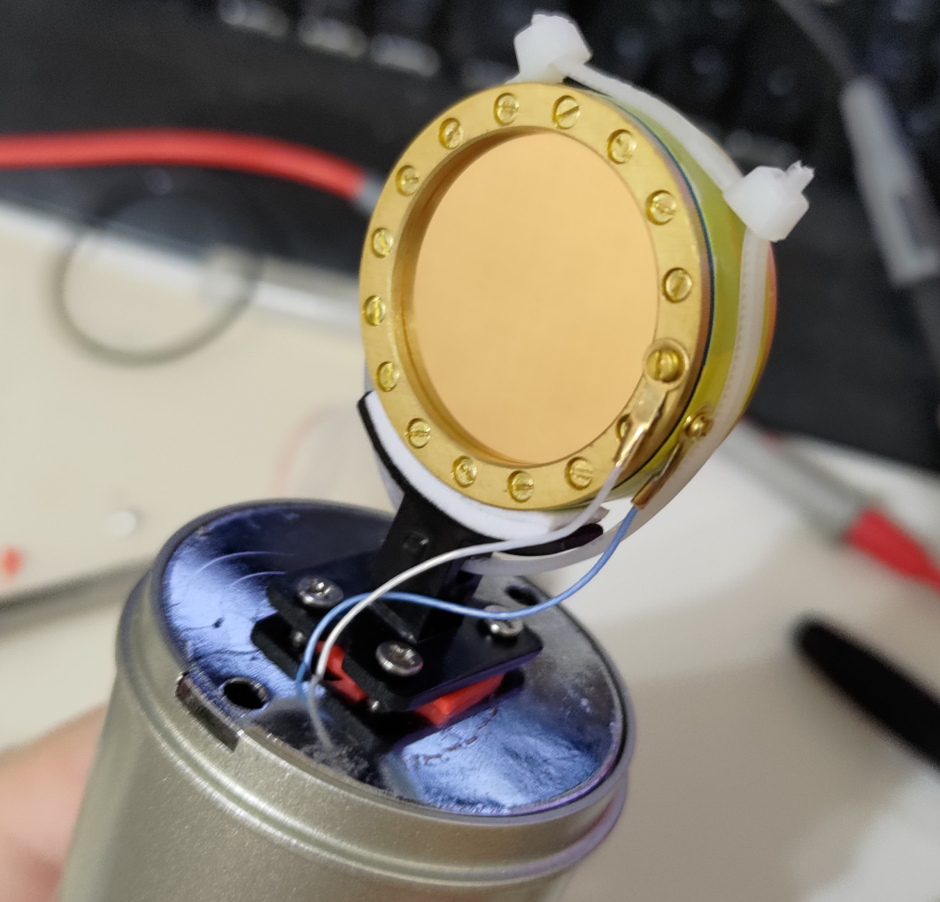
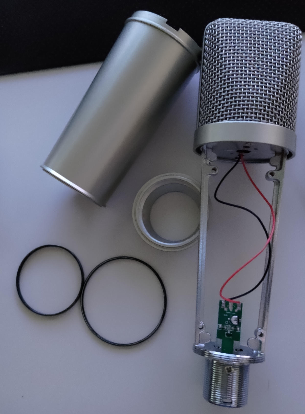
The microphone build uses a clone RK12/CK12 capsule($40-50 on Aliexpress/Ebay/etc, search for "edge terminated capsule"), a U87 donor body($15-30, also Aliexpress, search term "U87 mic"), and a custom preamp board($20-30, this project).
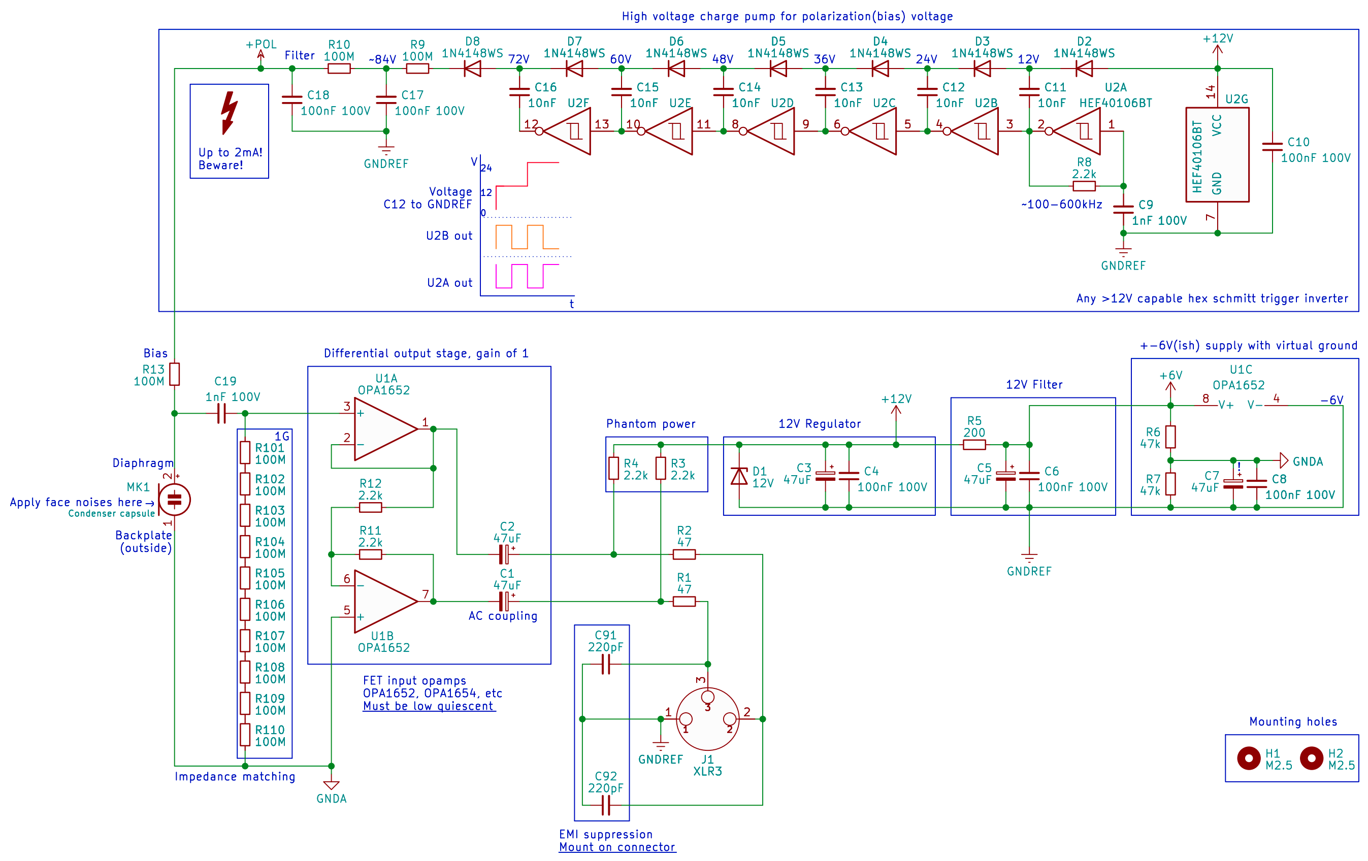
The board is very simple, yet high performance - it uses a dual FET input opamp in a single package to both convert the capsule's impedance and provide a differential signal, while the bias is provided by a slightly cursed hex schmitt trigger inverter charge pump.
With the setup pictured below, the results are, to the non-audiophool ear, perfect. There is practically no self-noise due to the simplicity of the circuit and performance of the chosen opamp, plenty of dynamic range, and no signal distortion/"coloration". You get exactly what the capsule sees on the XLR connector.
You can use pretty much any FET input opamp, however you must pay close attention to the quiescent current. This circuit uses a fairly high impedance power path, and the phantom power standard can't provide much current in the first place. Total power consumption of the two opamps should be no more than ~7-8mA(3.5-4mA per).
Same goes for the hex inverter in terms of power consumption, but otherwise anything will do. You can substitute the part with any 40106 clone of similar functionality.
Take care to purchase high voltage rated capacitors where specified - this is important! Ceramic capacitors lose capacitance at higher voltages, so X7R class caps rated at 100V or more are preferred(this won't explicitly solve derating, but it will help). All values are readily available in 0805 size, so it's not an issue.
Choose NP0/C0G capacitors for ceramics if your budget allows. They'll improve performance a little bit, but not by a whole lot. (this will solve derating, but at significant cost)
The design is licensed under the MIT license. If you want to build it, go ahead. If you want to sell it, also go ahead, but just mention this page or something. Pretty much none of this is really original and has been done dozens of times(i.e. DJJules/Sound Sleuth over at Instructables, whose circuit I took inspiration from), I just put my own twist on it.
Most cheap donor bodies will come pre-anodized or even pre-painted, including contact surfaces at separation points(circuit cover, headbasket, nut, spacers, etc), make sure to sand them down to expose metal, or you'll pick up tons of mains hum and other external electrical noise!
If you can't make or assemble the board yourself... well, uh, good luck, but most assembly houses in China will happily make them for you for not very much money. I had a PCBWay affiliate link here, but I wouldn't recommend dealing with them anymore.
(also available as pdf or KiCad 7 sources, see files)
| Qty | Value | Footprint | References |
|---|---|---|---|
| 13 | 100M | Resistor_SMD:R_0805_2012Metric | R9, R10, R13, R101, R102, R103, R104, R105, R106, R107, R108, R109, R110 |
| 7 | 1N4148WS | Diode_SMD:D_SOD-323_HandSoldering | D2, D3, D4, D5, D6, D7, D8 |
| 6 | 100nF 100V | Capacitor_SMD:C_0805_2012Metric | C4, C6, C8, C10, C17, C18 |
| 6 | 10nF | Capacitor_SMD:C_0805_2012Metric | C11, C12, C13, C14, C15, C16 |
| 5 | 2.2k | Resistor_SMD:R_0805_2012Metric | R3, R4, R8, R11, R12 |
| 5 | 47uF | Capacitor_SMD:CP_Elec_8x10.5 | C1, C2, C3, C5, C7 |
| 2 | 1nF 100V | Capacitor_SMD:C_0805_2012Metric | C9, C19 |
| 2 | 47 | Resistor_SMD:R_0805_2012Metric | R1, R2 |
| 2 | 47k | Resistor_SMD:R_0805_2012Metric | R6, R7 |
| 2 | M2.5 | MountingHole:MountingHole_2.7mm_M2.5_ISO14580 | H1, H2 |
| 1 | 12V | Diode_SMD:D_MiniMELF_Handsoldering | D1 |
| 1 | 200 | Resistor_SMD:R_0805_2012Metric | R5 |
| 1 | Condenser capsule | SpiritsKiCADLib:Pads_2pin_10mm | MK1 |
| 1 | G*** | kibuzzard-640955DC | kibuzzard-640955DC |
| 1 | G*** | kibuzzard-640955D5 | kibuzzard-640955D5 |
| 1 | G*** | kibuzzard-64095693 | kibuzzard-64095693 |
| 1 | G*** | kibuzzard-64153C1C | kibuzzard-64153C1C |
| 1 | G*** | kibuzzard-64153C31 | kibuzzard-64153C31 |
| 1 | G*** | kibuzzard-640955F0 | kibuzzard-640955F0 |
| 1 | G*** | kibuzzard-6409565D | kibuzzard-6409565D |
| 1 | HEF40106BT | Package_SO:SO-14_3.9x8.65mm_P1.27mm | U2 |
| 1 | OPA1652 | Package_SO:SOIC-8_3.9x4.9mm_P1.27mm | U1 |
| 1 | XLR3 | SpiritsKiCADLib:Pads_3pin_10mm | J1 |
bkshepherd/DaisySeedProjects
A collection of hardware and software projects based around the Electro-Smith Daisy Seed

GuitarML/GuitarPedalSTM32
Guitar pedal using a stm32h7 microcontroller programmed with CubeIDE (PCB and Firmware)

freeDSP/freeDSP-INFINITAS
USB Audio Class 2 compliant audio interface with up to 32 input and up to 32 output channels and optional ADAU1452 DSP.

freeDSP/FreeDSP_Catamaran_AB
A mono contruction Differntial 1 Input 4 output ADAU1701 DSP board, 96kHz TDM8 interlink is available.

levi2234/ChimeraMultiFX
ChimeraMultiFX is a dual-MCU effects pedal platform. The Daisy Seed handles audio DSP while the ESP32 manages controls, Wi-Fi, and the browser-based UI.


alxp1982/DaisySeedProjects
A collection of hardware and software projects based around the Electro-Smith Daisy Seed
It measures 40.9 × 85 mm and has 2 copper layers, 1.6 mm thick.
63 parts, built around the OPA1652AID, HEF40106BT, 1N4148WS and M2.5. The full list of its parts is on this page, with links to each part's symbol and footprint where PCBKit's library has them.
From the Spirit532/studio_mic repository on GitHub, at the commit this page was made from: the board is StudioMic.kicad_pcb and its schematic StudioMic.kicad_sch. PCBKit opens the board in the browser, with nothing to install.
Its repository publishes it under the MIT licence: you may reuse it on that licence's terms (keep the author's notice, and for a copyleft licence share your changes alike).