2 layers368.3 × 215.9 mm
 EtchedPixels/Mini1112
A 68HC11 SBC for the 68HC11A CPUs
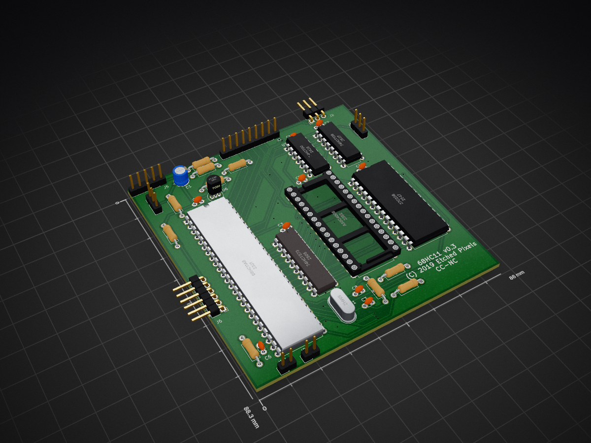
68hc11 is an open-source printed circuit board by EtchedPixels, from the EtchedPixels/Mini11 repository on GitHub, published under the GPL-3.0 licence. It is a 2-layer board of 86 × 88.3 mm with 36 parts on 61 nets, routed with 783 tracks and 51 vias.
It is built around the 27C256-17/J, 74HCT00D and 74HCT139D, with the 74HCT573D and DS1233 among its other parts. Its parts include 10 capacitors, 10 resistors, 7 ICs, 5 connectors and 1 crystal.


The Mini11 is a small board that is designed to provide a complete large 68HC11 environment with a fairly low chip count. It provides 16K of ROM and 512K of RAM as well as breaking out all the spare I/O including the serial and SPI in useful ways.
To keep cost down it's designed to use the many old 68HC11A series parts that can be found in junk boxes and old boards. This has a different pinout to the later processor variants.
As the 68HC11 can be serial bootstrapped it is possible to assemble the board and fit all the discrete parts and only the 68HC11 into its socket. Fit jumpers JP1 and JP2 and apply power. You should be able to talk to the board with db11 or similar tools.
If you have a part with ROM then you should also be able to boot from the ROM if you boot with JP1 and JP2 removed. If the ROM contains Buffalo as is usual then you will also need to jumper PE0 to ground. A 68HC11A8 with Buffalo should then produce a boot message and you'll be able to talk to the monitor.
The boot mode can also be used to check out the board after the other parts are fitted. You can boot in single chip mode and then use db11 to turn off the single chip mode and then check that the memory is behaving. Port A controls the memory banking. Bit 3 turns the ROM on and off, bits 4-6 are the memory bank.
With all the parts fitted you can burn firmware of choice into the ROM and with the jumpers removed the chip should boot the firmware. Remember to use the ".burn" file with the provided firmware or the tools to flip bit 0 and 2 as the board has D0 and D2 switched on the ROM
The provided firmware simply intializes the SD interface, loads the first sector and runs it.
You cannot run an unmodified Buffalo from the ROM. It uses Port A pins for tracing and this conflicts with the memory banking.
For a 27C256 you can load different firmware into each 16K bank and select using JP3. For a 28C256 burn the firmware into the upper 16K and jumper JP3 to VCC.
If you have problems with the 68HC11A such as it only coming up in bootstrap mode then there are a few things to check.
If the CONFIG byte is set to map in the internal ROM and the ROM contains garbage or is absent (eg on a 68HC11A0/A1 part) then you can boot it into single chip mode and use db11 to change the config byte to 0x0C or similar.
The internal EEROM has protection options and some devices wih custom firmware will set them. These can still be used as they will erase the EEPROM when the serial boot is triggered. This will put 0F into the CONFIG register so that will also then need reprogramming.
No.. opps
Simple three wire interface with no flow control. Usually run at 9600 baud.
SPI. Provides the expected SPI interfaces as well as two chip select lines, reset and the external IRQ (pulled up). Intended for an SD card and optionally additional devices with an SPI mux/demux board. Remember to use an SD adapter with voltage shifting.
5v and ground, needs to be properly regulated. The board has an onboard reset generator to handle power coming up gracefully.
Three input ports mapped to port A bits 0-2
Port E of the 68HC11.
Fit the jumper to set MODA low
Fit the jumper to set MODB low
Select bank on 27C256, set to 5V with a 28C256
At this point FUZIX. Build the "mini11" target, write the generated SD card image raw to an SD card and boot the mini11 with it inserted. The console runs at 9600 baud.
| Qty | Value | Footprint | References |
|---|---|---|---|
| 8 | 10K | Resistors_THT:R_Axial_DIN0207_L6.3mm_D2.5mm_P10.16mm_Horizontal | R1, R2, R3, R4, R5, R6, R7, R8 |
| 6 | 0.1uF | Capacitor_THT:C_Disc_D3.0mm_W1.6mm_P2.50mm | C2, C3, C4, C5, C6, C10 |
| 2 | 22pF | Capacitor_THT:C_Disc_D3.0mm_W1.6mm_P2.50mm | C7, C8 |
| 1 | 0.1uF | Capacitor_THT:C_Disc_D3.0mm_W2.0mm_P2.50mm | C9 |
| 1 | 10M | Resistors_THT:R_Axial_DIN0207_L6.3mm_D2.5mm_P10.16mm_Horizontal | R10 |
| 1 | 10uF | Capacitors_THT:CP_Radial_D5.0mm_P2.00mm | C1 |
| 1 | 1K | Resistors_THT:R_Axial_DIN0207_L6.3mm_D2.5mm_P10.16mm_Horizontal | R9 |
| 1 | 27C256 | Package_DIP:DIP-28_W15.24mm | U5 |
| 1 | 68HC11A8 | Housings_DIP:DIP-48_W15.24mm | U1 |
| 1 | 74HCT00 | Package_DIP:DIP-14_W7.62mm | U7 |
| 1 | 74HCT139 | Package_DIP:DIP-16_W7.62mm | U4 |
| 1 | 74HCT573 | Housings_DIP:DIP-20_W7.62mm | U3 |
| 1 | 8MHz | Crystals:Crystal_HC49-U_Vertical | Y1 |
| 1 | AS6C4008 | Housings_DIP:DIP-32_W15.24mm | U2 |
| 1 | Conn_01x03 | Connector_PinHeader_2.54mm:PinHeader_1x03_P2.54mm_Horizontal | J2 |
| 1 | Conn_01x03 | Connector_PinHeader_2.54mm:PinHeader_1x03_P2.54mm_Vertical | J4 |
| 1 | Conn_01x05 | Connector_PinHeader_2.54mm:PinHeader_1x05_P2.54mm_Vertical | J5 |
| 1 | Conn_01x06 | Connector_PinHeader_2.54mm:PinHeader_1x06_P2.54mm_Horizontal | J6 |
| 1 | Conn_01x09 | Connector_PinHeader_2.54mm:PinHeader_1x09_P2.54mm_Vertical | J3 |
| 1 | DS1233 | TO_SOT_Packages_THT:TO-92_Inline_Narrow_Oval | U6 |
| 1 | Jumper_3_Open | Connector_PinHeader_2.54mm:PinHeader_1x03_P2.54mm_Vertical | JP3 |
| 1 | MODA | Connector_PinHeader_2.54mm:PinHeader_1x02_P2.54mm_Vertical | JP1 |
| 1 | MODB | Connector_PinHeader_2.54mm:PinHeader_1x02_P2.54mm_Vertical | JP2 |
It measures 86 × 88.3 mm and has 2 copper layers, 1.6 mm thick.
36 parts, built around the 27C256-17/J, 74HCT00D, 74HCT139D and 74HCT573D. The full list of its parts is on this page, with links to each part's symbol and footprint where PCBKit's library has them.
From the EtchedPixels/Mini11 repository on GitHub, at the commit this page was made from: the board is Kicad/68hc11.kicad_pcb and its schematic Kicad/68hc11.kicad_sch. PCBKit opens the board in the browser, with nothing to install.
Its repository publishes it under the GPL-3.0 licence: you may reuse it on that licence's terms (keep the author's notice, and for a copyleft licence share your changes alike).


Julesc013/project-carbon
Hardware and software for custom CPUs, FPUs, and computer systems.


ja1umi/MUTIF1613Project
Verious design information related to my home-brewed MN1613 16-bit computer

danwerner21/CortexPC
Powertran Cortex clone. PC formfactor, based on Stuart Conner's MiniCortex
