2 layers235 × 160 mm
Processor.tms9995
lynchaj/duodyne
Duodyne is a hobbyist retrocomputer system designed to run ROMWBW. It is comprised of modules on a system bus
105 parts15

 danwerner21/CortexPC7
Powertran Cortex clone. PC formfactor, based on Stuart Conner's MiniCortex
CortexPC is an open-source printed circuit board by danwerner21, from the danwerner21/CortexPC repository on GitHub. It is a 2-layer board of 244 × 244 mm with 167 parts on 421 nets, routed with 7,418 tracks and 394 vias.
It is built around the ATTINY85-20PU, 74LS245SC and LM386, with the 27C256-17/J, 74LS32SC and 74LS374PC among its other parts. Its parts include 53 capacitors, 38 connectors, 28 ICs, 23 resistors and 8 diodes. It belongs with the AVR (ATmega, ATtiny) and FPGA and CPLD boards of this library.


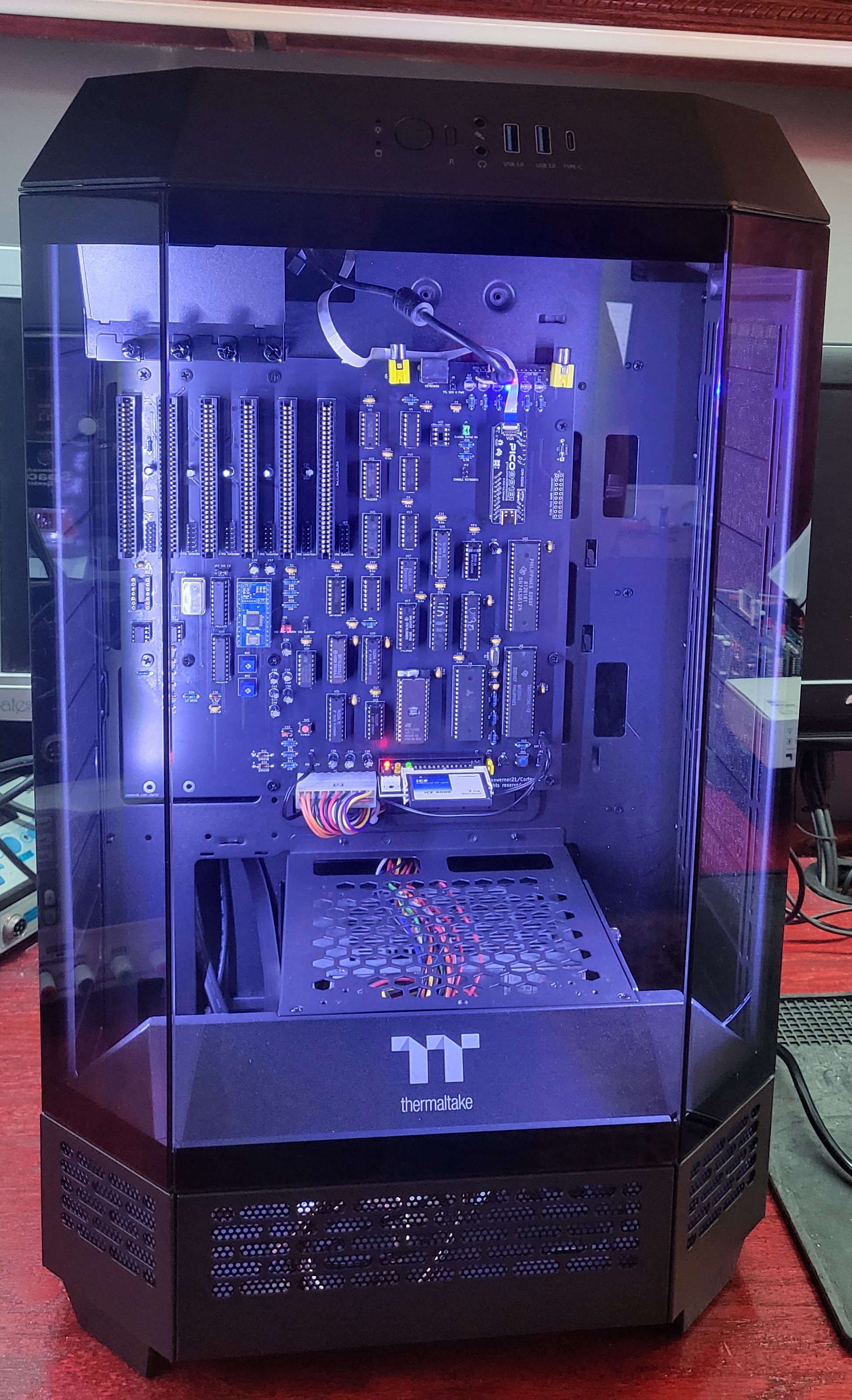
This is an ATX format implimentation of the Mini-Cortex system by Paul Ruizendaal and Stuart Conner. The Mini-Cortex system is a further development of a TMS 9995 breadboard project to produce a system similar to a Powertran Cortex, but using more modern components. The system is based around a TMS 9995 running at 3 MHz, with 32K byte EEPROM, and will use 512K bytes of RAM accessed through a memory mapper. An on-board serial port and IDE interface exists on the card. There is also provisions for a TMS9918 clone, a keyboard and some expansion slots -- these are not totally supported by the firmware at this time however.
The main EEPROM image provides a boot menu which enables the user to select between the EVMBUG system monitor from TI's TMS 9995 Evaluation Module, a port of the Powertran Cortex Power BASIC made for a TM 990 computer, the Marinchip Disk Executive (MDEX) operating system, and an implementation of V6 Unix including a C compiler.
Much more information can be found at Stuart's site
The memory map is shown in the table below.
Memory Address	Mapped To
>0000 - >7FFF	ROM when enabled, otherwise RAM
>8000 - >EFFF	RAM
>F000 - >F0FB	TMS 9995 internal RAM
>F0FC - >FDFF	RAM
>FE00 - >FE03	CF card ATA registers
>FE08 - >FE08	SN76489 SOUND
>FE20 - >FE21	Video
>FE40 - >FE4F	Memory mapper registers 0-15
>FE60 - >FE7F	SID Chip
>FE80 - >FEBF	Offboard IO (ports $80-$FF)
>FFF0 - >FFF9	RAM
>FFFA - >FFFF	TMS 9995 internal RAM

CRU Address	Mapped To
>0000 - >003F	TMS 9902 registers
>0040 - >007F	Control signal latch (further details here)
 	(Plus processor internal CRU bits)

(Note that in TI Speak ">" means Hexidecimal, so for the rest of us >FFFA is the same as $FFFA or 0xFFFA or FFFAH)
for more information see Stuart's site
The CF card has to be newly formatted with an MBR (master boot record), a single partition formatted as FAT32, and a cluster size of 4096 bytes - the CF card needs to be at least 256 MB to support this. Not all brands/sizes of CF card seem to work - you may have more success with an older, low capacity card. A SanDisk 2.0GB card with a "SDCFB" marking on the back works well.
It can be problematic formatting a new card using Windows 10 as it does not always seem to write an MBR to the card. I use a formatting utility called Rufus details and download here with Boot selection==Non bootable, Partition Scheme==MBR, File System=FAT32, and Cluster Size= 4096 Bytes. Once the card is correctly formatted, use Windows to write the four files from the software folder ZIP filedirectly to the card. for more information see Stuart's site
  P6 - ATX Case Power Button
  JP1- ATX Case Reset Button
  JP3- SID Chip CS (Some SID replacement chips need 2-3, default 1-2)
  J21- Enable SID Audio Amp
  J20- SID Speaker Out
  J22- SN76489 Audio Amp
  J23- SN76489 Speaker Out
  J1 - F18A TANG NANO Connector
  J4 - Serial Interrupt Enabled (Required for UNIX)
  J5 - TTL Serial Interface
  J6 - TTL Serial Power Enable
  JP2- Enable Keyboard Interface
  JP4- ATX Case IDE Led output
  JP5- IDE Power Enable (2-3 for VCC on IDE Pin 20)
The serial port on the TMS9995 board is configured for 9600 Baud, 7 data bits, even parity, one stop bit, no flow control.
The EVMBUG monitor and the boot loaders for MDEX and Unix, are stored on a single 32K byte EEPROM. The required application is selected from a boot menu. To display the boot menu, connect the board to a configured serial port on a PC, apply power then press any key.
You should then see:
  ___         _           ___  ___
 / __|___ _ _| |_ _____ _| _ \/ __|
| (__/ _ \ '_|  _/ -_) \ /  _/ (__
 \___\___/_|  \__\___/_\_\_|  \___|

TMS9995 COMPUTER SYSTEM
BIOS V1.0

PRESS 1 FOR EVMBUG MONITOR
PRESS 2 FOR MDEX
PRESS 3 FOR UNIX
To select a software application from the menu, press the corresponding numeric key.
MDEX documentation is available on the site http://www.powertrancortex.com/documentation.html. The documentation and MDEX disks were recovered and made available by Dave Hunter, the owner of the www.powertrancortex.com site. Porting of the MDEX files to the Mini-Cortex was by Paul Ruizendaal. On the Mini-Cortex, the files are stored in two emulated disks on the CF card.
The first version of Unix ported was LSX Unix (https://www.mailcom.com/lsx/), which was designed to run with 40K byte RAM and two 256K byte floppies. LSX Unix was adapted from Unix V6 by Dr. Heinz Lycklama (https://www.60bits.net/msu/mycomp/terak/termubel.htm). This port has been further ported to the TI 990 minicomputer by Dave Pitts, who has also made improvements to the code build system.
Dave Pitts' TI-990 web page. EVMBUG documentation
The first test image tests just the processor (TMS9995_test_1_eprom_image), the EPROM and the EPROM chip select logic. Program and fit the EPROM, power on, press the reset switch. The CPU should execute a loop from ROM., then use the logic probe to check for a series of pulses on pin 20 of the EPROM every 2 seconds or so.
If the first test passes, repeat with the second test image (TMS9995_test_2_eprom_image), which also tests the RAM and the RAM chip select logic. With the second test, a series of pulses should be seen on pin 20 of the EPROM every 6 seconds or so.
The third test image has two versions. The first version configures the serial port to 9600 Baud, 7 bits/character, even parity, 2 stops bits, no flow control, and then loops continually sending the ASCII characters >21 ("!") to >7E . This version tests most of the system including ROM and RAM. The second version is a ROM only version. It also configures the serial port to 9600 Baud, 7 bits/character, even parity, 2 stops bits, no flow control, and then loops continually sending the ASCII characters >21 ("!") to >7E , but does not use any external RAM.
| Reference | Value | Qty | Description |
|---|---|---|---|
| C1,C2,C3,C4,C5,C6,C7,C8,C9,C10,C11,C12,C13,C14,C15,C16,C17,C19,C21,C23,C25,C27,C29 | 0.1u | 23 | |
| C18,C20,C22,C24 | 10u | 4 | |
| C26 | 22u | 1 | |
| C28 | 47uF | 1 | |
| C30 | 1uF | 1 | Polarized capacitor |
| C31 | 10uF | 1 | Polarized capacitor |
| C32 | 0.1 uF | 1 | Unpolarized capacitor |
| C33 | 0.01 uF | 1 | Unpolarized capacitor |
| C34 | 100µF | 1 | |
| C35 | 0.1µF | 1 | |
| C40,C41 | 15pf | 2 | |
| D1 | PWR | 1 | LED |
| D2 | IDLE | 1 | LED |
| D3 | MAP | 1 | LED |
| D5 | 1N5817 | 1 | 20V 1A Schottky Barrier Rectifier Diode, DO-41 |
| D6 | IDE ACT | 1 | LED |
| D8 | Tx | 1 | LED |
| D9 | Rx | 1 | LED |
| D10,D11 | 1N4148 | 2 | 100V 0.15A standard switching diode, DO-35 |
| J1 | F18A TANG NANO Connector | 1 | Generic connector, double row, 02x10, odd/even pin numbering scheme (row 1 odd numbers, row 2 even numbers), script generated (kicad-library-utils/schlib/autogen/connector/) |
| J2,J8,J11,J13,J15,J17 | IRQ Selection | 6 | Generic connector, double row, 02x06, odd/even pin numbering scheme (row 1 odd numbers, row 2 even numbers), script generated (kicad-library-utils/schlib/autogen/connector/) |
| J3,J10,J12,J14,J16,J18 | Bus_I_not_SA_8bit | 6 | 8-bit ISA-PC bus connector |
| J4 | Enable Serial Int | 1 | Generic connector, single row, 01x02, script generated |
| J5 | TTL SERIAL 0 | 1 | |
| J6 | TTL SER 0 PWR | 1 | |
| J7 | USER OUT | 1 | Generic connector, single row, 01x07, script generated |
| J9 | AUDIO OUT | 1 | coaxial connector (BNC, SMA, SMB, SMC, Cinch/RCA, LEMO, ...) |
| J19 | Parallel Keyboard IN | 1 | Generic connector, single row, 01x11, script generated |
| JP1 | JUMPER | 1 | Generic connector, single row, 01x02, script generated (kicad-library-utils/schlib/autogen/connector/) |
| JP4 | EXT IDE LED | 1 | |
| JP5 | IDE PWR | 1 | |
| P1 | 14.31818 MHz CLK | 1 | |
| P4 | 8 BIT IDE (CF) | 1 | |
| P5 | CONN_10X2 | 1 | Generic connector, double row, 02x10, odd/even pin numbering scheme (row 1 odd numbers, row 2 even numbers), script generated (kicad-library-utils/schlib/autogen/connector/) |
| P6 | POWER_SW | 1 | Generic connector, single row, 01x02, script generated (kicad-library-utils/schlib/autogen/connector/) |
| R1,R3,R6,R7,R11,R12,R13,R17 | 470 | 8 | -- mixed values -- |
| R2,R4,R8,R10,R14 | 10K | 5 | |
| R5 | 1000 | 1 | Resistor |
| R9 | 10Ω | 1 | |
| R16,R18 | 10k | 2 | Resistor |
| SW1 | RESET | 1 | Push button switch, generic, two pins |
| SW2 | POWER | 1 | Push button switch, generic, two pins |
| U1 | 74LS14 | 1 | |
| U2 | 74LS07 | 1 | |
| U3 | TMS9995-DIP_1 | 1 | |
| U4 | 74LS04 | 1 | |
| U5,U27 | 74LS74 | 2 | -- mixed values -- |
| U6 | 74LS112 | 1 | |
| U7 | SN76489 | 1 | |
| U8 | DS1233 | 1 | |
| U9 | SRAM_512K | 1 | 512K x 8 Low Power CMOS RAM, DIP-32 |
| U10 | TMS9918 EMU | 1 | |
| U11,U30 | GAL22V10 | 2 | |
| U12,U13 | 74LS32 | 2 | Quad 2-input OR |
| U14,U28,U29,U31 | 74LS244 | 4 | Octal Buffer and Line Driver With 3-State Output, active-low enables, non-inverting outputs |
| U15 | 74LS138 | 1 | |
| U17 | 74LS688 | 1 | |
| U18 | 27C256 | 1 | |
| U21 | TMS9902A | 1 | |
| U22 | 74LS259 | 1 | |
| U23 | 74LS612-DIP | 1 | |
| U25 | 74LS245 | 1 | Octal BUS Transceivers, 3-State outputs |
| U26 | 74HCT14 | 1 | Hex inverter schmitt trigger |
| Y1 | 12MHz | 1 |
| Qty | Value | Footprint | References |
|---|---|---|---|
| 23 | 0.1u | Custom:STD_DDW_CAP | C1, C2, C10, C11, C12, C13, C14, C15, C16, C17, C19, C21, C23, C25, C27, C29 +7 |
| 12 | CONN_1 | MountingHole:MountingHole_3.2mm_M3_Pad_TopBottom | P2, P7, P9, P10, P11, P12, P13, P14, P15, P16, P17, P18 |
| 8 | 470 | Custom:STD_DDW_RESISTOR | R1, R3, R6, R7, R11, R12, R13, R17 |
| 6 | Bus_I_not_SA_8bit | Custom:BUSPC_HOST | J3, J10, J12, J14, J16, J18 |
| 6 | IRQ Selection | Custom:STD_DDW_PINHEAD_V_2x06 | J2, J8, J11, J13, J15, J17 |
| 5 | 10k | Custom:STD_DDW_RESISTOR | R16, R18, R28, R29, R30 |
| 4 | 10K | Custom:STD_DDW_RESISTOR | R2, R4, R8, R14 |
| 4 | 10u | Custom:STD_DDW_PCAP | C18, C20, C22, C24 |
| 4 | 10uf | Custom:STD_DDW_PCAP | C39, C43, C49, C58 |
| 3 | 74LS244 | Custom:STD_DDW_DIP20 | U28, U29, U31 |
| 2 | 0.047uf | Custom:STD_DDW_CAP | C47, C56 |
| 2 | 0.1 uF | Custom:STD_DDW_CAP | C32, C37 |
| 2 | 10 ohms | Custom:STD_DDW_RESISTOR | R15, R24 |
| 2 | 10K | Potentiometer_THT:Potentiometer_Bourns_3386F_Vertical | RV1, RV2 |
| 2 | 15pf | Custom:STD_DDW_CAP | C40, C41 |
| 2 | 1N4148 | Custom:STD_DDW_DIODE | D10, D11 |
| 2 | 2200pf | Custom:STD_DDW_CAP | C42, C46 |
| 2 | 220uf | Custom:STD_DDW_PCAP | C48, C57 |
| 2 | 4.7K | Custom:STD_DDW_RESISTOR | R26, R27 |
| 2 | 470pf | Custom:STD_DDW_CAP | C44, C45 |
| 2 | 74LS32 | Custom:STD_DDW_DIP14 | U12, U13 |
| 2 | 74LS374 | Custom:STD_DDW_DIP20 | U19, U20 |
| 2 | 74LS74 | Custom:STD_DDW_DIP14 | U5, U27 |
| 2 | GAL22V10 | Custom:STD_DDW_DIP24_Skinny | U11, U30 |
| 2 | LM386 | Custom:STD_DDW_DIP8 | U24, U32 |
| 1 | 0.01 uF | Custom:STD_DDW_CAP | C33 |
| 1 | 0.1µF | Custom:STD_DDW_CAP | C35 |
| 1 | 0.22uf | Custom:STD_DDW_PCAP | C38 |
| 1 | 0.47uf | Custom:STD_DDW_PCAP | C50 |
| 1 | 1 MHz CLK | Custom:STD_DDW_DIP14 | P3 |
| 1 | 1000 | Custom:STD_DDW_RESISTOR | R5 |
| 1 | 100µF | Custom:STD_DDW_PCAP | C34 |
| 1 | 10uF | Custom:STD_DDW_PCAP | C31 |
| 1 | 10Ω | Custom:STD_DDW_RESISTOR | R9 |
| 1 | 12MHz | Custom:STD_DDW_XTAL | Y1 |
| 1 | 14.31818 MHz CLK | Custom:STD_DDW_DIP14 | P1 |
| 1 | 1N5817 | Custom:STD_DDW_DIODE | D5 |
| 1 | 1uF | Custom:STD_DDW_PCAP | C30 |
| 1 | 22u | Custom:STD_DDW_PCAP | C26 |
| 1 | 27C256 | Custom:STD_DDW_DIP28 | U18 |
| 1 | 4.7pF | Custom:STD_DDW_CAP | C36 |
| 1 | 47uF | Custom:STD_DDW_PCAP | C28 |
| 1 | 6581 | Custom:STD_DDW_DIP28 | U16 |
| 1 | 74HCT14 | Custom:STD_DDW_DIP14 | U26 |
| 1 | 74LS04 | Custom:STD_DDW_DIP14 | U4 |
| 1 | 74LS07 | Custom:STD_DDW_DIP14 | U2 |
| 1 | 74LS112 | Custom:STD_DDW_DIP16 | U6 |
| 1 | 74LS138 | Custom:STD_DDW_DIP16 | U15 |
| 1 | 74LS245 | Custom:STD_DDW_DIP20 | U25 |
| 1 | 74LS259 | Custom:STD_DDW_DIP16 | U22 |
| 1 | 74LS612-DIP | Custom:STD_DDW_DIP40 | U23 |
| 1 | 74LS688 | Custom:STD_DDW_DIP20 | U17 |
| 1 | 8 BIT IDE (CF) | Custom:STD_DDW_PINHEAD_V_2x20 | P4 |
| 1 | ATtiny85-20P | Custom:STD_DDW_DIP8 | U33 |
| 1 | AUDIO OUT | Custom:CUI_RCJ-047 | J9 |
| 1 | CONN_10X2 | Custom:ATXConnector | P5 |
| 1 | DS1233 | Custom:STD_DDW_TO92 | U8 |
| 1 | ENABLE KEYBOARD | Custom:STD_DDW_PINHEAD_V_1x02 | JP2 |
| 1 | EXT IDE LED | Custom:STD_DDW_PINHEAD_V_1x02 | JP4 |
| 1 | Enable Serial Int | Custom:STD_DDW_PINHEAD_V_1x02 | J4 |
| 1 | F18A TANG NANO Connector | Custom:STD_DDW_PinHeader_2x10 | J1 |
| 1 | IDE ACT | Custom:STD_DDW_LED5 | D6 |
| 1 | IDE PWR | Custom:STD_DDW_PINHEAD_V_1x03 | JP5 |
| 1 | IDLE | Custom:STD_DDW_LED5 | D2 |
| 1 | JUMPER | Custom:STD_DDW_PINHEAD_V_1x02 | JP1 |
| 1 | KEYBOARD | Custom:PS2_DIN | J19 |
| 1 | MAP | Custom:STD_DDW_LED5 | D3 |
| 1 | POWER | Custom:STD_DDW_TACTSW | SW2 |
| 1 | POWER_SW | Custom:STD_DDW_PINHEAD_V_1x02 | P6 |
| 1 | PWR | Custom:STD_DDW_LED5 | D1 |
| 1 | RESET | Custom:STD_DDW_TACTSW | SW1 |
| 1 | Rx | Custom:STD_DDW_LED5 | D9 |
| 1 | SID AMP Enable | Custom:STD_DDW_PINHEAD_V_1x02 | J21 |
| 1 | SID CS | Custom:STD_DDW_PINHEAD_V_1x03 | JP3 |
| 1 | SID OUT | Custom:CUI_RCJ-047 | J24 |
| 1 | SID Speaker | Custom:STD_DDW_PINHEAD_V_1x02 | J20 |
| 1 | SN76489 | Custom:STD_DDW_DIP16 | U7 |
| 1 | SN76489 AMP Enable | Custom:STD_DDW_PINHEAD_V_1x02 | J22 |
| 1 | SN76489 Speaker | Custom:STD_DDW_PINHEAD_V_1x02 | J23 |
| 1 | SRAM_512K | Custom:STD_DDW_DIP32 | U9 |
The 160 most common of 167 parts.
It measures 244 × 244 mm and has 2 copper layers, 1.6 mm thick.
167 parts, built around the ATTINY85-20PU, 74LS245SC, LM386 and 27C256-17/J. The full list of its parts is on this page, with links to each part's symbol and footprint where PCBKit's library has them.
From the danwerner21/CortexPC repository on GitHub, at the commit this page was made from: the board is Hardware/CortexPC.kicad_pcb and its schematic Hardware/CortexPC.kicad_sch. PCBKit opens the board in the browser, with nothing to install.
Its repository states no licence, so its author keeps all rights: ask danwerner21 before reusing the design.
lynchaj/duodyne
Duodyne is a hobbyist retrocomputer system designed to run ROMWBW. It is comprised of modules on a system bus


raymondh2/CompaqPortableIII
Current PCB Memory Expansion board layout is untested. The backplane for the expansion cards is tested and working.

fortinsylvain/MyCpu
Home brew CPU Hardware with 1-bit ALU implementation using 74LSxx, a micro-code and assembler coded in C#.


frubem/NE_Delta_Schematics
Forked from https://codeberg.org/hkzlab/NE_Delta_Schematics


hkzlab/CGA_Redux
The Color Graphics Adapter Redux board is a more or less faithful clone of the original IBM CGA, based on the original schematics