2 layers140 × 100 mm

 ersatzavian/yellow_fuzz
A bass fuzz for my good friend! Don't tell him, it's a surprise. Starting with a Boss MT-2 (I know, ew, don't tell anybody) because that's allegedly how Arion Salazar got most of his fuzz tone's on Third Eye Blind's…
Yellow fuzz dev is an open-source printed circuit board by ersatzavian, from the ersatzavian/yellow_fuzz repository on GitHub. It is a 2-layer board of 121.9 × 149.9 mm with 165 parts on 111 nets, routed with 989 tracks and 149 vias.
It is built around the TL072CP, BC817-25-TP and BAS16W, with the PTV111-4420A-A104, 1N34A and DMN2041L among its other parts. Its parts include 66 resistors, 50 capacitors, 14 transistors, 12 connectors and 11 diodes.


A bass fuzz for my good friend! Don't tell him, it's a surprise. Starting with a Boss MT-2 (I know, ew, don't tell anybody) because that's allegedly how Arion Salazar got most of his fuzz tone's on Third Eye Blind's self-titled (check out 2:20-2:30 in Graduate, of 4:10 in Thanks a Lot if you like yours with phaser). Hell yeah we want that, don't pretend you don't like that record.
Formerly "yellow fuzz" after BRC's "yellow bikes" that happen to be green. Didn't like the sound of it, now it's the Graduator.
Rev01 (non form-factor) has been built, brought up, and play tested.
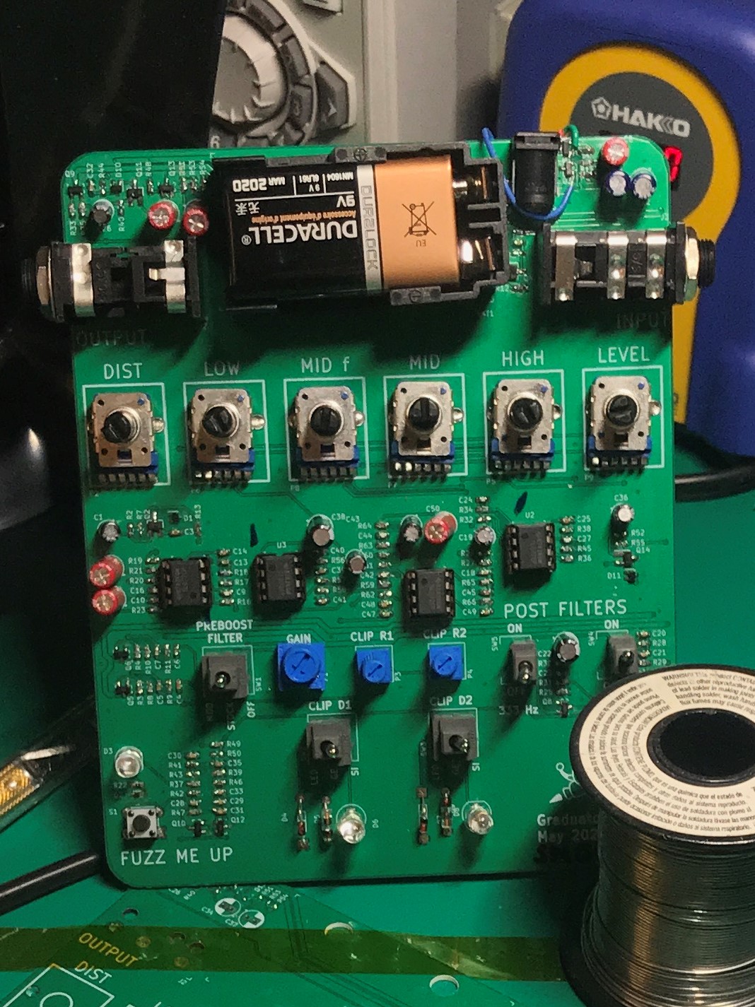
Electric Druid has an awesome write-up on the key circuit blocks in the original MT-2 design that's worth a read. If you want a comprehensive survey of the guts of this pedal, read that, then the mods section below, and you're done.
Controls are described by order in the signal chain, rather than physical layout.
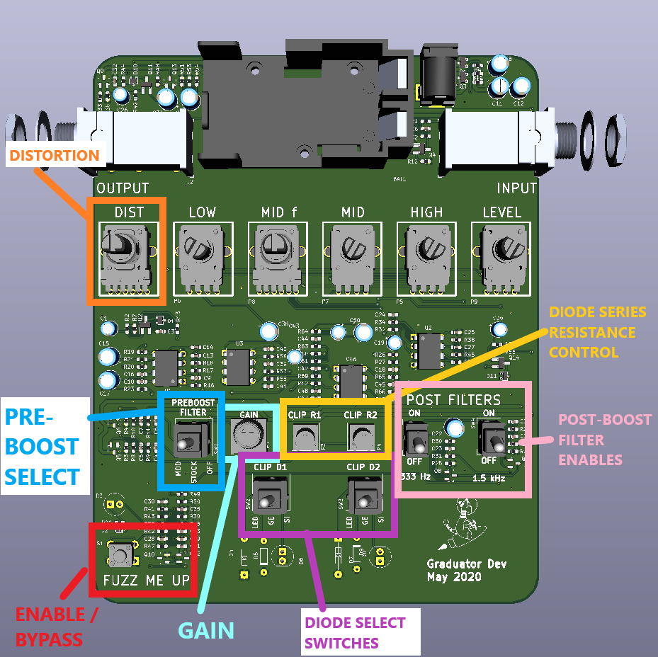
| Control | Original MT-2 Control, or Experiment | Circuit Block | What's it Do? |
|---|---|---|---|
| Gain | Experiment | Distortion Block - First Op-Amp Stage Gain, P1. 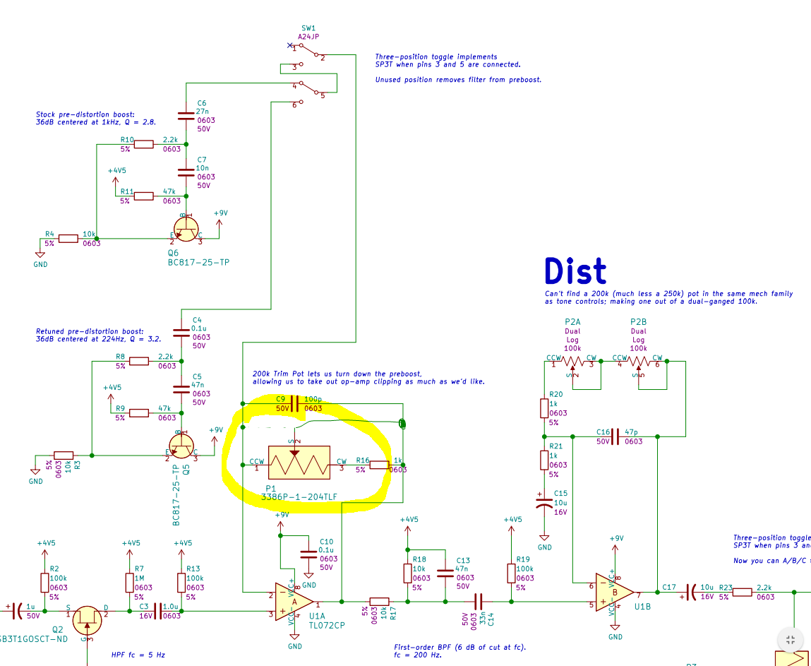 | The "pre-distortion" gain block does two things:
|
| Pre-Boost Filter Select | Experiment | Distortion Block - First Op-Amp Stage Gyrator Select, SW1. 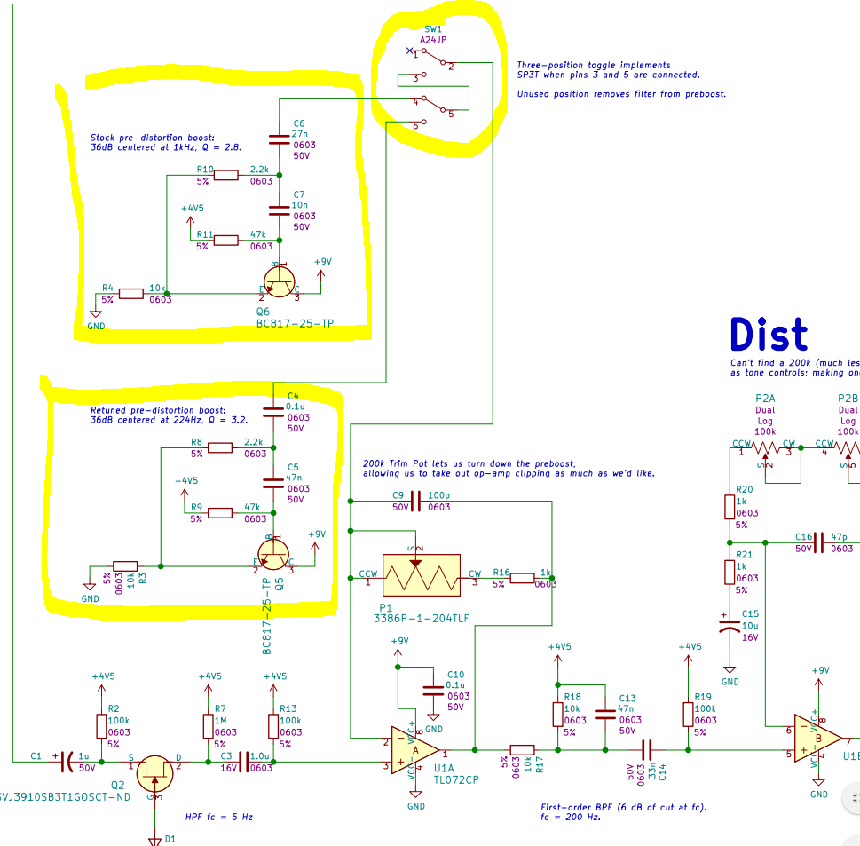 | As you can read about here, "gyrators" are nifty little active circuit blocks that let you make a thing that acts like an inductor out of a capacitor and a transistor or op-amp. Why not just use an inductor is a good question and is covered in that guide in good detail. For our purposes here, this control lets you pick between two filters, or a third disable setting:
|
| Distortion | Original | Distortion Block - Second Op-Amp Stage Gain, P2A/B. 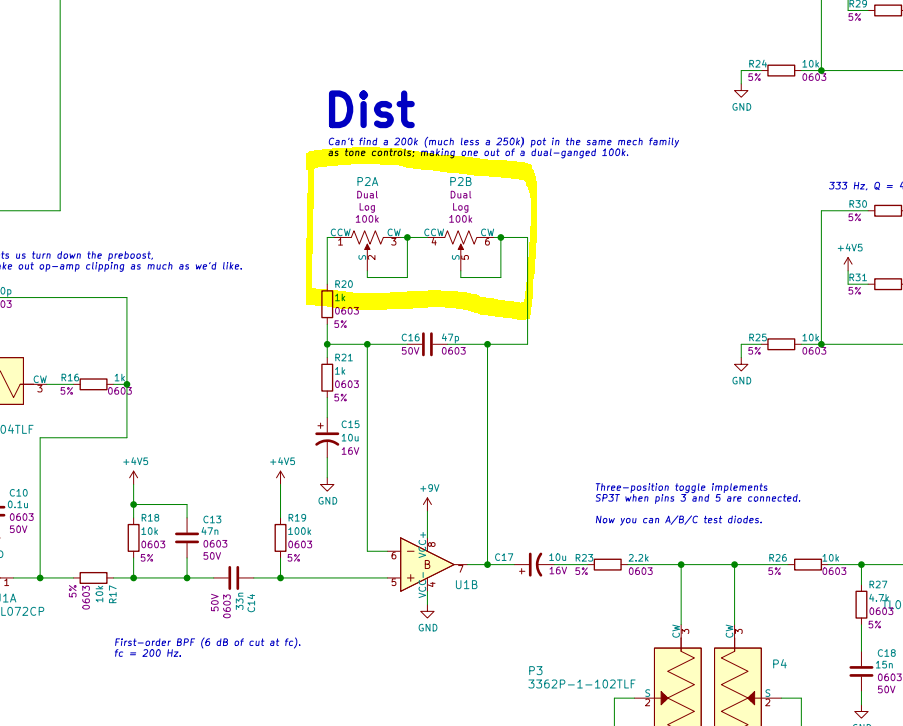 | Controls the gain of the second op-amp stage before the diode limiter that really clips the signal. Running this op-amp at high gain will boost the signal to the "rails", and you'll get very hard, square peaks, before you even hit the diode limiter. There are many different sources of distortion in this pedal, it's definitely not all up to just one circuit block to hammer your signal into a mess. |
| Diode Select Switches | Experiment | Distortion Block - Diode Limiting Stage, SW2 / SW3 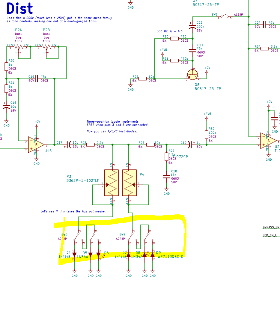 | The core of this pedal, as with many distortion pedals, is the diode limiter. This stage takes your nice sine-shaped waveform and clips the peaks off of it when they exceed the forward voltage of the diodes. Different diodes have different forward voltages, and different response "shapes" as they effectively turn on and off. The internet is full of forums where people will swear that this diode does this or that and sounds this way or that way, and many of them are subjectively right but nearly all of them are oversimplifying the test case they're talking about. Since there are so many sources of distortion in this (and every) circuit, you're hearing them all. The diode is just part of it. Anyway, this mod lets you pick between three different kinds of diode for your limiter. Even weirder, it lets you choose the diode for the top and bottom half of your waveform separately, so you can produce very "asymmetric" distortion. Right now, you have:
|
| Diode Series Resistance Control | Experiment | Distortion Block - Diode Limiting Stage, P3 / P4. 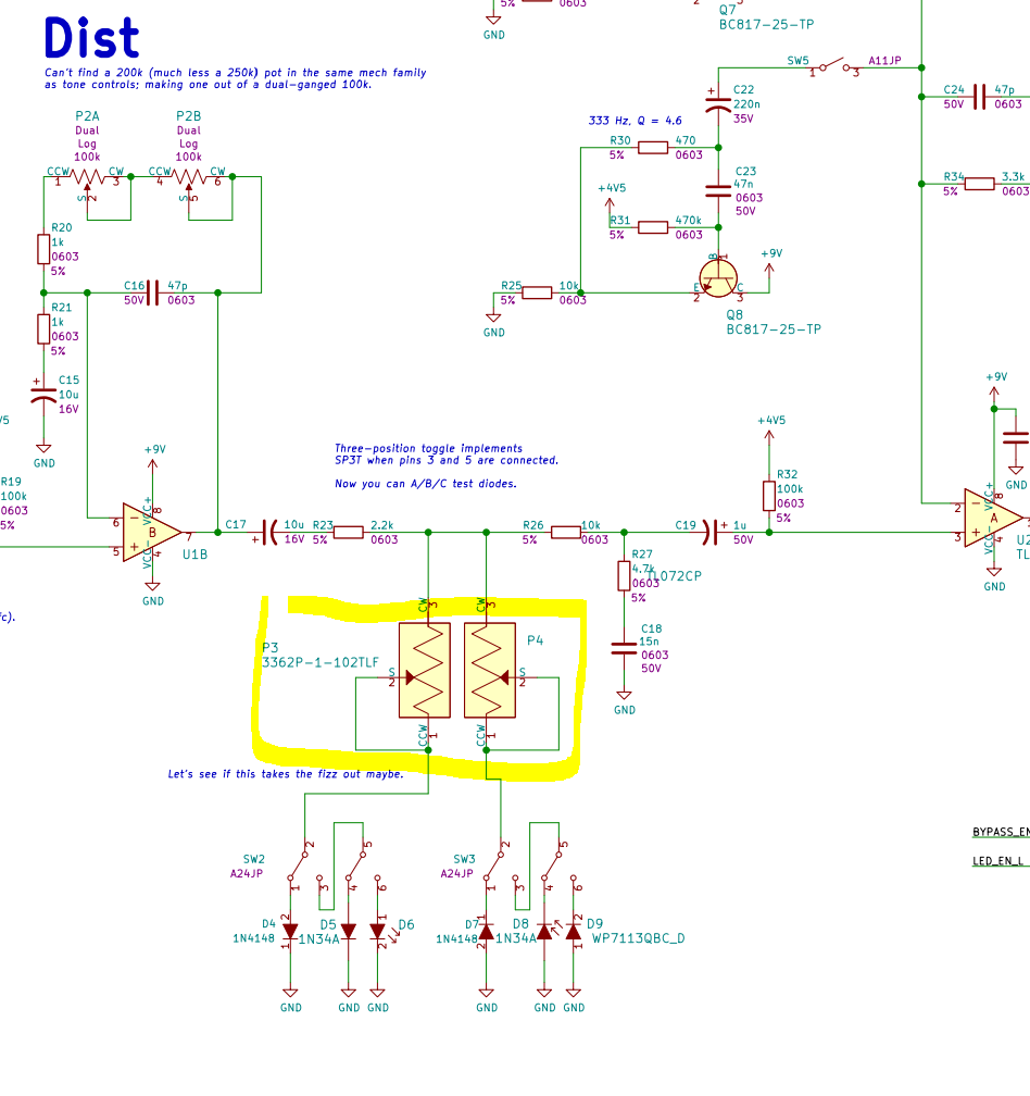 | Diode clipping can be very harsh and introduce harmonics that you wouldn't get from, say, output stage distortion in a tube amplifier, which can sound really buzzy and cheap and not great. In an attempt to prevent this, I added 1k potentiometers - variable resistors - in series with the diodes, to soften the "knee" when they turn on and off and try and reduce that fuzz. In practice, the EQ section of this pedal has way, way more impact on the harmonic content that makes it out of the pedal, and I find this control completely inaudible. |
| Post-Boost Filter Enables | Experiment | Distortion Block - after Diode Limiting Stage, SW4 / SW5. 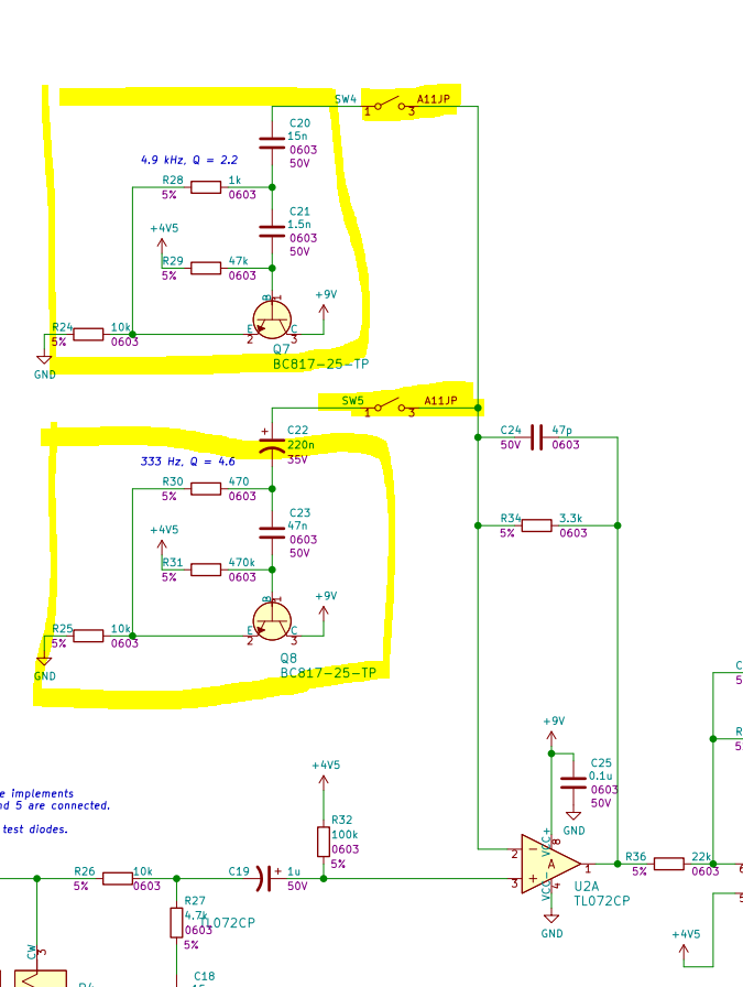 | The original MT-2 includes this stage with both Gyrator sections included, which provides a "double-humped" bandpass boost. In the original, the two sections are:
|
| EQ - Low | Original | Tone Block | The original "low shelf" control, a band-pass filter centered at 105 Hz with a Q of 3.1, which can provide up to 20dB of cut or boost. The whole EQ section is covered very nicely with plots in the Electric Druid guide, highly recommend. |
| EQ - Mid Frequency | Original | Tone Block | The original "mid frequency" control, which controls the center of the mid band-pass filter. Filter center frequency can be swept from about 200 Hz to about 7 kHz. This control would be a lot better as a log taper pot, to spread the frequencies of interest logarithmically along the range of the pot, but a dual-ganged log-taper 50kΩ pot is not an easy thing to find. As a result, you'll hear this control really come to life between about 1 o-clock and 5 o-clock. |
| EQ - Mid | Original | Tone Block | Cut or boost up to 15 dB with the mid-band filter centered wherever you put it with the Mid Frequency knob. |
| EQ - High | Original | Tone Block | High Shelf EQ, begins to kick in around 1kHz, where it offers around 6 dB of cut or boost, and flattens around 10 kHz, where it offers around 20 kHz of cut or boost. |
| Level | Original | Tone Block | You know what this does. |
| Enable / Bypass | Original | Switching Section | You know what this does too. |
| Change | Goal | Done |
|---|---|---|
| Make gyrators after clipping stage optional (see C24/C25, C20/C17) | Experiment with pedal character to reduce fizz and deliver more even tone to the eq section so I can hear the difference. | Yes |
| Add bypass option for preboost stage. | Try to reduce fizz. | Yes |
| Add series variable resistors (trim pots) to clipping diodes D3/D4. | Try to reduce fizz. | Yes |
| Add selector switch for 3 different diode options in each direction. | Experiment with higher Vf (LEDs) and give germanium a whirl. | Yes |
| Issue | Workaround | Fix | Fixed in Master |
|---|---|---|---|
| C2 and R6 ref designators are swapped. HTML BOM shows correct outlines. | Install per HTML BOM. | Swap ref des back. | |
| R4, R6-7, R12, R14-15, R17-18, R24-26, R33, R51 MPN is for 1k part, should be 10k (part description on BOM is correct, but MPN is wrong). | Install 10k part. | Update component in lib. | |
| R14 and R15 ref des are colliding. | N/A | Fix in layout. | |
| NSVJ3910SB3T1G was replaced in order with J113, which is a through-hole part and won't fit. | Order correct part. | Make sure MPN in design is correct and orderable. | |
| PTV111-4420-A104 was missing from kit, got extra PTV112-4420-A104 instead. | Cut leads 1 and 2, bend 3-6 down to fit into pads 1-4 to use just one pot of the two in the package. | Order the right thing. | |
| PTV111-4420-A503 was missing from kit, got extra PTV112-4420-A503 instead. | Cut leads 1 and 2, bend 3-6 down to fit into pads 1-4 to use just one pot of the two in the package. | Order the right thing. | |
| Nichicon UST1H010MDD1TE footprint is wrong (C1, C19, C26, C36, C43, C46): lead spacing is nto correct, part leads are flared for wider spacing than footprint. | Bend leads back. | Correct footprint. | |
| D6 missing MPN info. | N/A | Correct part library ref. | |
| No test points, doh. | N/A | Add some ground test points and stage-to-stage test points and jumpers. | |
| 22 Ohm series-R on power rail, why even would you do that? | Short that. | Remove that. | |
| Polarity marks on op-amps are not visible enough, and are obscured when sockets are installed (U1 was installed rotated 180 degrees in first build). | Note polarity carefully during build. | Improve op amp polarity marks. | |
| Pre-distortion boost gain pot P1 is backwards (CCW for more) | Turn it the other way, or snip top-side trace between pins 1-2, short pins 1-3. 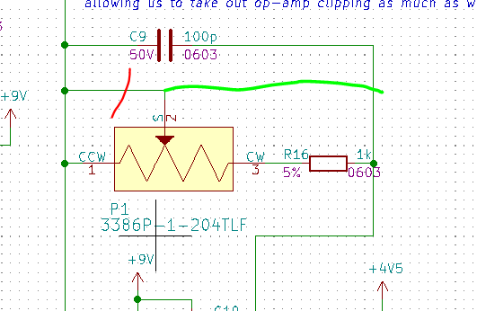 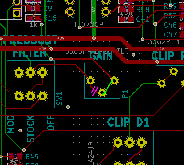 | Correct in schematic. | |
| Dual pots installed in P5, P6, P7, and P9 with pins 3-6 slid over into pads 1-4 don't match design correctly. | Double-check pinout of these parts and revise rework used to place dual pots in single-pot footprints. | Use the parts on the BOM, duh. | |
Duplicate TONE_OUT net names caused short across level pot. 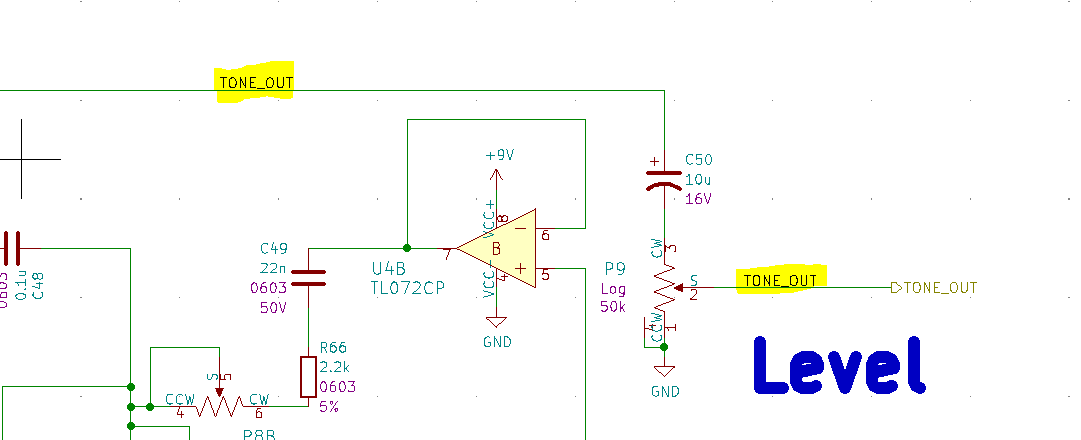 | Cut extra trace on top layer. 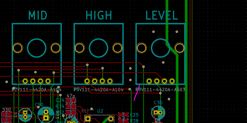 | Remove duplicate net label. | |
| Incorrectly routed jack as center-positive, which makes the battery not work at all. | Cut and swap traces to make center-negative. 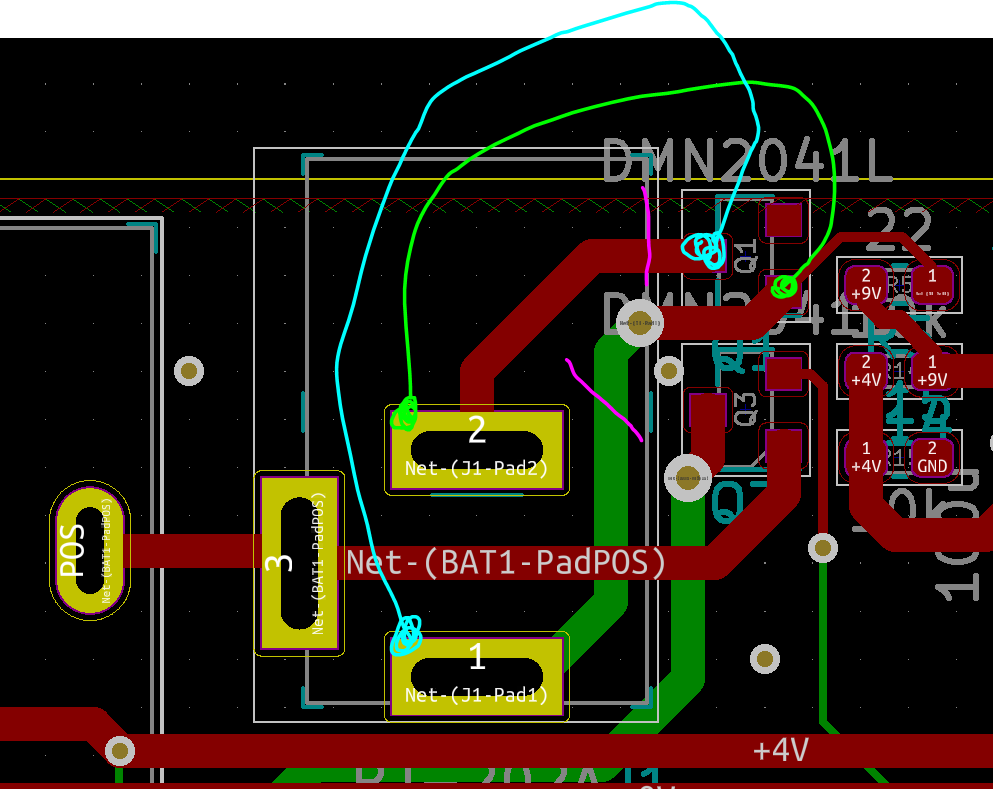 | Permanentify rework. | |
| Mid frequency control only does much between about 1-o-clock and 5-o-clock. | Use as is. | Try once more to find a log pot... good luck. | |
| Pre-boost filter select switch SW1 should probably have a resistor on its unused pole, rather than having fixed gain and taking the "gain" control out of the mix. |
| Qty | Value | Footprint | References |
|---|---|---|---|
| 14 | 10k | Resistor_SMD:R_0603_1608Metric_Pad1.05x0.95mm_HandSolder | R1, R3, R4, R12, R14, R15, R17, R18, R24, R25, R26, R33, R35, R51 |
| 9 | 100k | Resistor_SMD:R_0603_1608Metric_Pad1.05x0.95mm_HandSolder | R2, R13, R19, R32, R42, R46, R48, R53, R57 |
| 9 | 1M | Resistor_SMD:R_0603_1608Metric_Pad1.05x0.95mm_HandSolder | R6, R7, R40, R43, R44, R50, R52, R55, R62 |
| 8 | BC817-25-TP | digikey:SOT-23-3 | Q5, Q6, Q7, Q8, Q9, Q10, Q12, Q13 |
| 7 | 2.2k | Resistor_SMD:R_0603_1608Metric_Pad1.05x0.95mm_HandSolder | R8, R10, R23, R56, R58, R65, R66 |
| 7 | 47n | Capacitor_SMD:C_0603_1608Metric_Pad1.05x0.95mm_HandSolder | C2, C5, C13, C23, C32, C35, C39 |
| 6 | 0.1u | Capacitor_SMD:C_0603_1608Metric_Pad1.05x0.95mm_HandSolder | C4, C10, C25, C40, C45, C48 |
| 6 | 1u | Capacitor_THT:CP_Radial_D4.0mm_P1.50mm | C1, C19, C26, C36, C43, C46 |
| 5 | 10u | Capacitor_THT:CP_Radial_D5.0mm_P2.00mm | C15, C17, C34, C37, C50 |
| 5 | 1k | Resistor_SMD:R_0603_1608Metric_Pad1.05x0.95mm_HandSolder | R16, R20, R21, R28, R54 |
| 5 | 47k | Resistor_SMD:R_0603_1608Metric_Pad1.05x0.95mm_HandSolder | R9, R11, R29, R61, R63 |
| 4 | 22k | Resistor_SMD:R_0603_1608Metric_Pad1.05x0.95mm_HandSolder | R36, R38, R45, R59 |
| 4 | 56k | Resistor_SMD:R_0603_1608Metric_Pad1.05x0.95mm_HandSolder | R37, R39, R47, R49 |
| 4 | NSVJ3910SB3T1GOSCT-ND | Package_TO_SOT_SMD:SOT-23_Handsoldering | Q2, Q4, Q11, Q14 |
| 4 | TL072CP | yellow_fuzz_dev:DIP-8_W7.62mm | U1, U2, U3, U4 |
| 3 | 100u | Capacitor_THT:CP_Radial_D5.0mm_P2.00mm | C8, C11, C12 |
| 3 | 10n | Capacitor_SMD:C_0603_1608Metric_Pad1.05x0.95mm_HandSolder | C7, C30, C41 |
| 3 | BAS16W | Package_TO_SOT_SMD:SOT-323_SC-70 | D1, D10, D11 |
| 3 | PTV111-4420A-A104 | yellow_fuzz_dev:Potentiometer_Bourns_PTV111_4420A_Single_Vertical | P5, P6, P7 |
| 3 | SW_SP3T_A24JP | yellow_fuzz_dev:A24JP | SW1, SW2, SW3 |
| 3 | WP7113QBC_D | digikey:LED_5mm_Radial | D3, D6, D9 |
| 2 | 100p | Capacitor_SMD:C_0603_1608Metric_Pad1.05x0.95mm_HandSolder | C9, C44 |
| 2 | 10p | Capacitor_SMD:C_0603_1608Metric_Pad1.05x0.95mm_HandSolder | C27, C42 |
| 2 | 15n | Capacitor_SMD:C_0603_1608Metric_Pad1.05x0.95mm_HandSolder | C18, C20 |
| 2 | 1N34A | digikey:DO-35 | D5, D8 |
| 2 | 1N4148 | digikey:Diode_DO-35_P10mm | D4, D7 |
| 2 | 220n | Capacitor_THT:CP_Radial_D5.0mm_P2.00mm | C22, C38 |
| 2 | 220p | Capacitor_SMD:C_0603_1608Metric_Pad1.05x0.95mm_HandSolder | C29, C31 |
| 2 | 330 | Resistor_SMD:R_0603_1608Metric_Pad1.05x0.95mm_HandSolder | R60, R64 |
| 2 | 3362P-1-102TLF | yellow_fuzz_dev:3362PT | P3, P4 |
| 2 | 470p | Capacitor_SMD:C_0603_1608Metric_Pad1.05x0.95mm_HandSolder | C28, C33 |
| 2 | 47p | Capacitor_SMD:C_0603_1608Metric_Pad1.05x0.95mm_HandSolder | C16, C24 |
| 2 | DMN2041L | Package_TO_SOT_SMD:SOT-23 | Q1, Q3 |
| 2 | SW_SPST_A11JP | yellow_fuzz_dev:A11JP | SW4, SW5 |
| 1 | 1.0u | Capacitor_SMD:C_0603_1608Metric_Pad1.05x0.95mm_HandSolder | C3 |
| 1 | 1.2k | Resistor_SMD:R_0603_1608Metric_Pad1.05x0.95mm_HandSolder | R22 |
| 1 | 1.5n | Capacitor_SMD:C_0603_1608Metric_Pad1.05x0.95mm_HandSolder | C21 |
| 1 | 100 | Resistor_SMD:R_0603_1608Metric_Pad1.05x0.95mm_HandSolder | R41 |
| 1 | 1825910-6 | yellow_fuzz_dev:Switch_Tactile_THT_6x6mm | S1 |
| 1 | 22 | Resistor_SMD:R_0603_1608Metric_Pad1.05x0.95mm_HandSolder | R5 |
| 1 | 22n | Capacitor_SMD:C_0603_1608Metric_Pad1.05x0.95mm_HandSolder | C49 |
| 1 | 27n | Capacitor_SMD:C_0603_1608Metric_Pad1.05x0.95mm_HandSolder | C6 |
| 1 | 3.3k | Resistor_SMD:R_0603_1608Metric_Pad1.05x0.95mm_HandSolder | R34 |
| 1 | 3386P-1-204TLF | yellow_fuzz_dev:3386P | P1 |
| 1 | 33n | Capacitor_SMD:C_0603_1608Metric_Pad1.05x0.95mm_HandSolder | C14 |
| 1 | 4.7k | Resistor_SMD:R_0603_1608Metric_Pad1.05x0.95mm_HandSolder | R27 |
| 1 | 470 | Resistor_SMD:R_0603_1608Metric_Pad1.05x0.95mm_HandSolder | R30 |
| 1 | 470k | Resistor_SMD:R_0603_1608Metric_Pad1.05x0.95mm_HandSolder | R31 |
| 1 | 8.2n | Capacitor_SMD:C_0603_1608Metric_Pad1.05x0.95mm_HandSolder | C47 |
| 1 | BC9VPC | yellow_fuzz_dev:Battery_Holder_9V_BC9VPC-ND | BAT1 |
| 1 | DZ2S056X0L | Diode_SMD:D_SOD-523 | D2 |
| 1 | LOGO | yellow_fuzz_dev:amph_1_5x1_5 | G*** |
| 1 | PJ-202A | yellow_fuzz_dev:Barrel_Jack_5.5mmODx2.1mmID_PJ-202A | J1 |
| 1 | PTV111-4420A-A503 | yellow_fuzz_dev:Potentiometer_Bourns_PTV111_4420A_Single_Vertical | P9 |
| 1 | PTV112-4420A-A104 | yellow_fuzz_dev:Potentiometer_Bourns_PTV112_3417A_Dual_Vertical | P2 |
| 1 | PTV112-4420A-A503 | yellow_fuzz_dev:Potentiometer_Bourns_PTV112_3417A_Dual_Vertical | P8 |
| 1 | RA49B11 | yellow_fuzz_dev:Headphone_Jack_6.35mm_SN49B12B | J2 |
| 1 | SN49B12B | yellow_fuzz_dev:Headphone_Jack_6.35mm_SN49B12B | J3 |

Poky88/HAPCAN_Modul_RFID_CTECKA
This repository contains complete hardware and software resources for the development and implementation of a new extension module for the HAPCAN home automation system.

AudioMorphology/ParrotRev2
Parrot is a 12hp Eurorack digital delay powered by a Raspberry Pi Pico microcontroller.


MaximSpeczyk/IoT-FPGA
University Project Teamwork for Advanced Embedded Systems and Hardware Engineering.

DOLUWAMU-TAIWO/TD
Avdanced Embdedded Labs (IOT) And Hardware Engineering (PCB/VHDL)

KrystianRuszczak/BioSense
The hardware design files in this directory are licensed under CERN-OHL-P-2.0. See LICENSE.
It measures 121.9 × 149.9 mm and has 2 copper layers, 1.59 mm thick.
165 parts, built around the TL072CP, BC817-25-TP, BAS16W and PTV111-4420A-A104. The full list of its parts is on this page, with links to each part's symbol and footprint where PCBKit's library has them.
From the ersatzavian/yellow_fuzz repository on GitHub, at the commit this page was made from: the board is yellow_fuzz_dev/yellow_fuzz_dev.kicad_pcb. PCBKit opens the board in the browser, with nothing to install.
Its repository states no licence, so its author keeps all rights: ask ersatzavian before reusing the design.