2 layers94 × 74.2 mm
 erdmannp/make_trotec_ttp_smart
Small project which adds a humidity control, a small pump, MQTT and wifi to the TTP5E
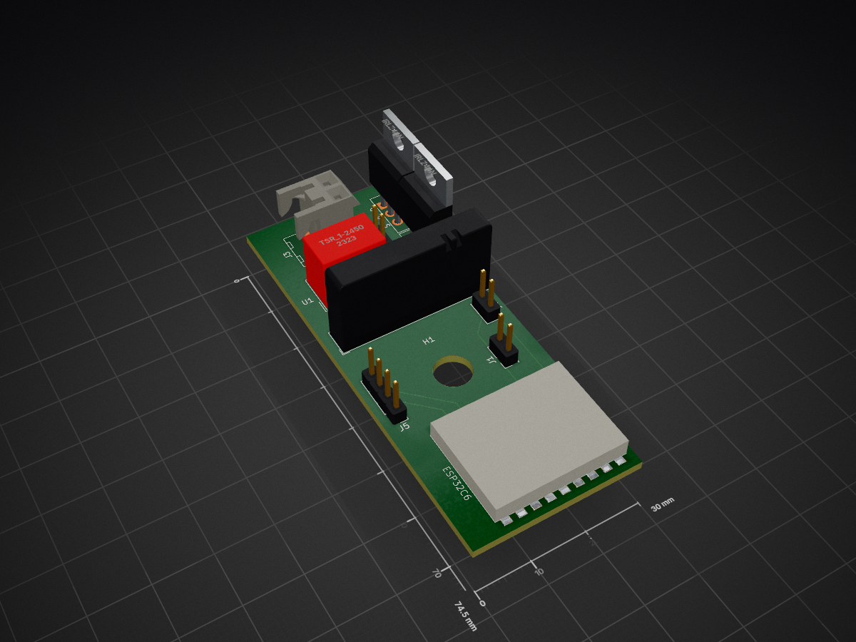
Ttp5 mqtt is an open-source printed circuit board by erdmannp, from the erdmannp/make_trotec_ttp_smart repository on GitHub, published under the GPL-3.0 licence. It is a 4-layer board of 30 × 74.5 mm with 15 parts on 24 nets, routed with 106 tracks and 4 vias.
It is built around the TSR 1-2450 and IRLZ44N. Its parts include 5 connectors, 3 resistors, 2 transistors, 1 capacitor and 1 IC. It belongs with the home automation and IoT and radio and wireless boards of this library.


I bought a used Troted TTP5, which is a peltier based dehumidifier. It is absolutely sufficient for small rooms like my bathroom. But it only has two modes: On and Off. The original PCB looks like this:
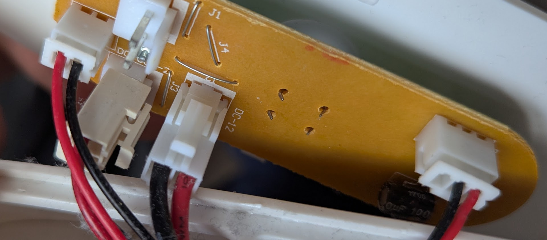
The 9 Volt input power is connected to the "DC-12" port. Peltier and Fan are connected in the left of this image. The connector on the right is the "water level high" switch. In this model it is literally a switch which is turned on by a high water level.
My idea is to take the "water level high" signal input and "reuse" it as the enable or disable of the dehumidifier. So when turned on the dehumidifier will no longer be on, it will only be used if the humidity sensor shows a value below the threshold. The TTP5 PCB will act like the watertank is full, in case of low humidity or watertank full.
I designed the PCB in a way that it is piggybacked by the normal PCB:
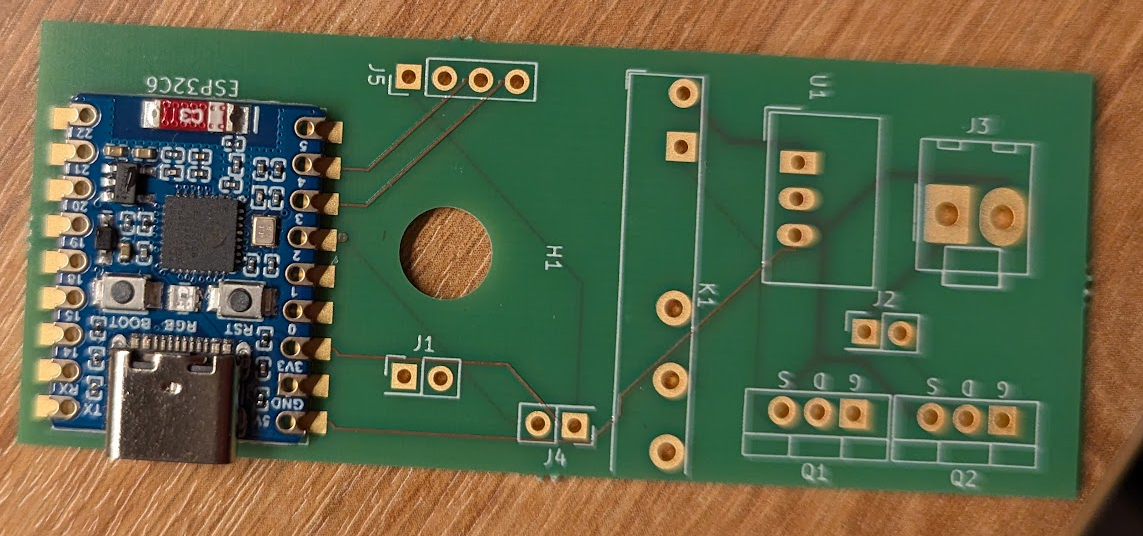
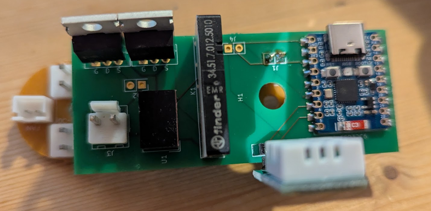
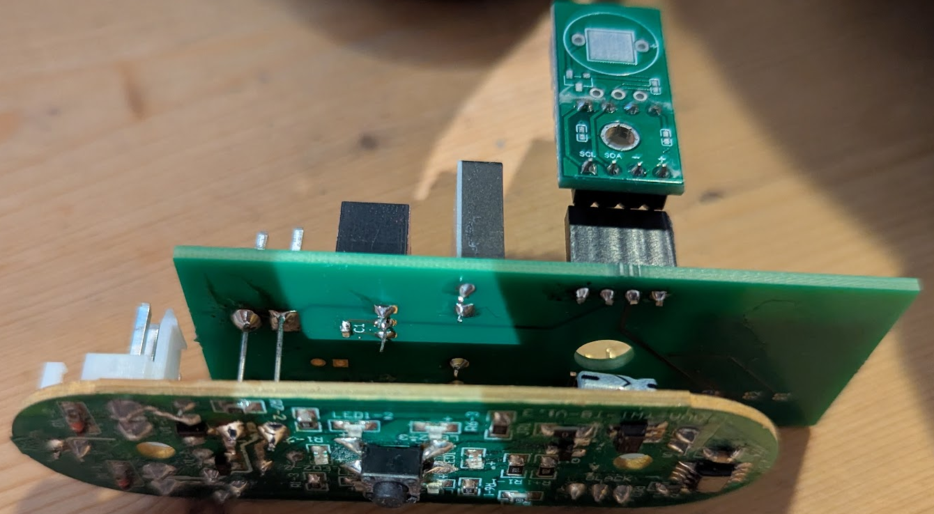
The "water level high" signal is now handled by the added PCB.
After a testphase I connected the humidity sensor inside of the TTP5 chassis.
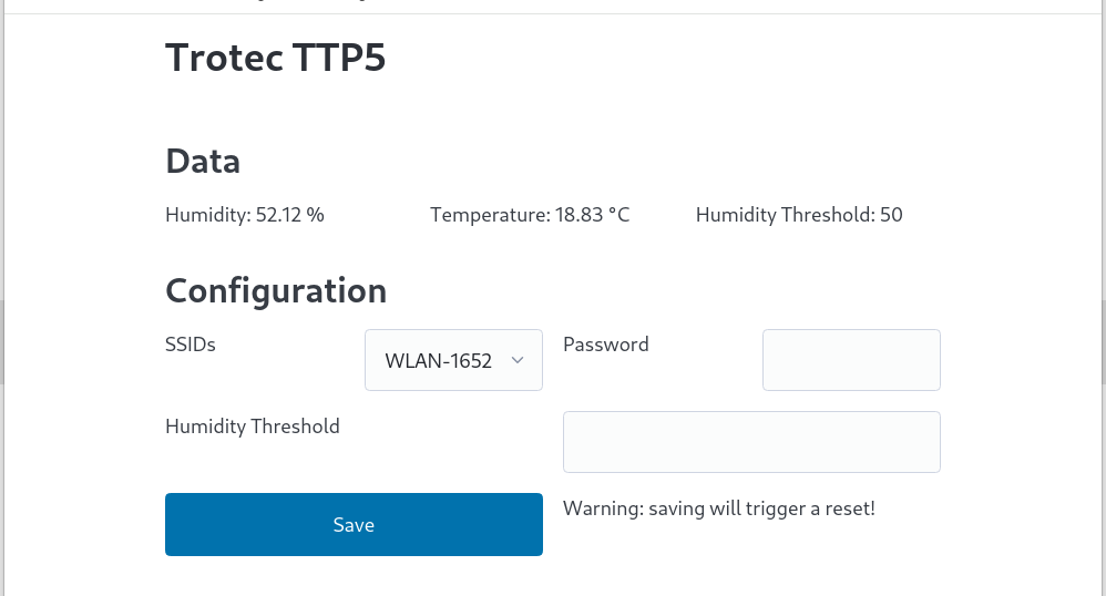
The configuration Webinterface is very rudimental, but it does the job.
| Qty | Value | Footprint | References |
|---|---|---|---|
| 3 | 47k | Resistor_SMD:R_0201_0603Metric_Pad0.64x0.40mm_HandSolder | R1, R2, R3 |
| 2 | IRLZ44N | PCM_Package_TO_SOT_THT_AKL:TO-220-3_Vertical_GDS | Q1, Q2 |
| 1 | 22n | Resistor_SMD:R_0603_1608Metric_Pad0.98x0.95mm_HandSolder | C1 |
| 1 | Conn_01x04 | Connector_PinHeader_2.54mm:PinHeader_1x04_P2.54mm_Vertical | J5 |
| 1 | Conn_Power | Connector_Molex:Molex_KK-396_A-41791-0002_1x02_P3.96mm_Vertical | J3 |
| 1 | Conn_pump | Connector_PinHeader_2.54mm:PinHeader_2x01_P2.54mm_Vertical | J2 |
| 1 | Conn_water | Connector_PinHeader_2.54mm:PinHeader_2x01_P2.54mm_Vertical | J1 |
| 1 | Conn_waterlevel | Connector_PinHeader_2.54mm:PinHeader_2x01_P2.54mm_Vertical | J4 |
| 1 | FINDER-34.51 | Relay_THT:Relay_SPDT_Finder_34.51_Vertical | K1 |
| 1 | MountingHole | MountingHole:MountingHole_6.5mm | H1 |
| 1 | TSR_1-2450 | Converter_DCDC:Converter_DCDC_TRACO_TSR-1_THT | U1 |
| 1 | ~ | Waveshare:Waveshare ESP32-C6 Mini Development Board | ESP32C6 |

corygrant/dingoPDM
Hardware - dingoPDM is an open source, affordable automotive PDM (Power Distribution Module). Pre-assembled and tested units are available or the design can be used to build a DIY version.

hberntsen/mhi-ac-ctrl-esp32
Control MHI Airconditioning locally using your own ESP32 series chip!


idlehandsdev/shark_bait
The files and firmware for the Shark Bait wireless pumping system.

It measures 30 × 74.5 mm and has 4 copper layers, 1.6 mm thick.
15 parts, built around the TSR 1-2450 and IRLZ44N. The full list of its parts is on this page, with links to each part's symbol and footprint where PCBKit's library has them.
From the erdmannp/make_trotec_ttp_smart repository on GitHub, at the commit this page was made from: the board is kicad/ttp5_mqtt/ttp5_mqtt.kicad_pcb and its schematic kicad/ttp5_mqtt/ttp5_mqtt.kicad_sch. PCBKit opens the board in the browser, with nothing to install.
Its repository publishes it under the GPL-3.0 licence: you may reuse it on that licence's terms (keep the author's notice, and for a copyleft licence share your changes alike).