2 layers

 fehlfarbe/terraesp25
ESP32 terrarium controller
Terraesp is an open-source printed circuit board by fehlfarbe, from the fehlfarbe/terraesp repository on GitHub, published under the MIT licence. It is a 2-layer board of 127 × 54.3 mm with 83 parts on 69 nets, routed with 377 tracks and 39 vias.
It is built around the TSR 1-2450, AMS1117 and DMG4800LSD, with the COM-11821 and TAJA226M010RNJ among its other parts. Its parts include 27 resistors, 6 diodes, 4 switches, 4 fuses and 3 capacitors. It belongs with the ESP32 boards of this library.


With this project you can control your terrarium's temperature, light, sprinkler and so on via webinterface.
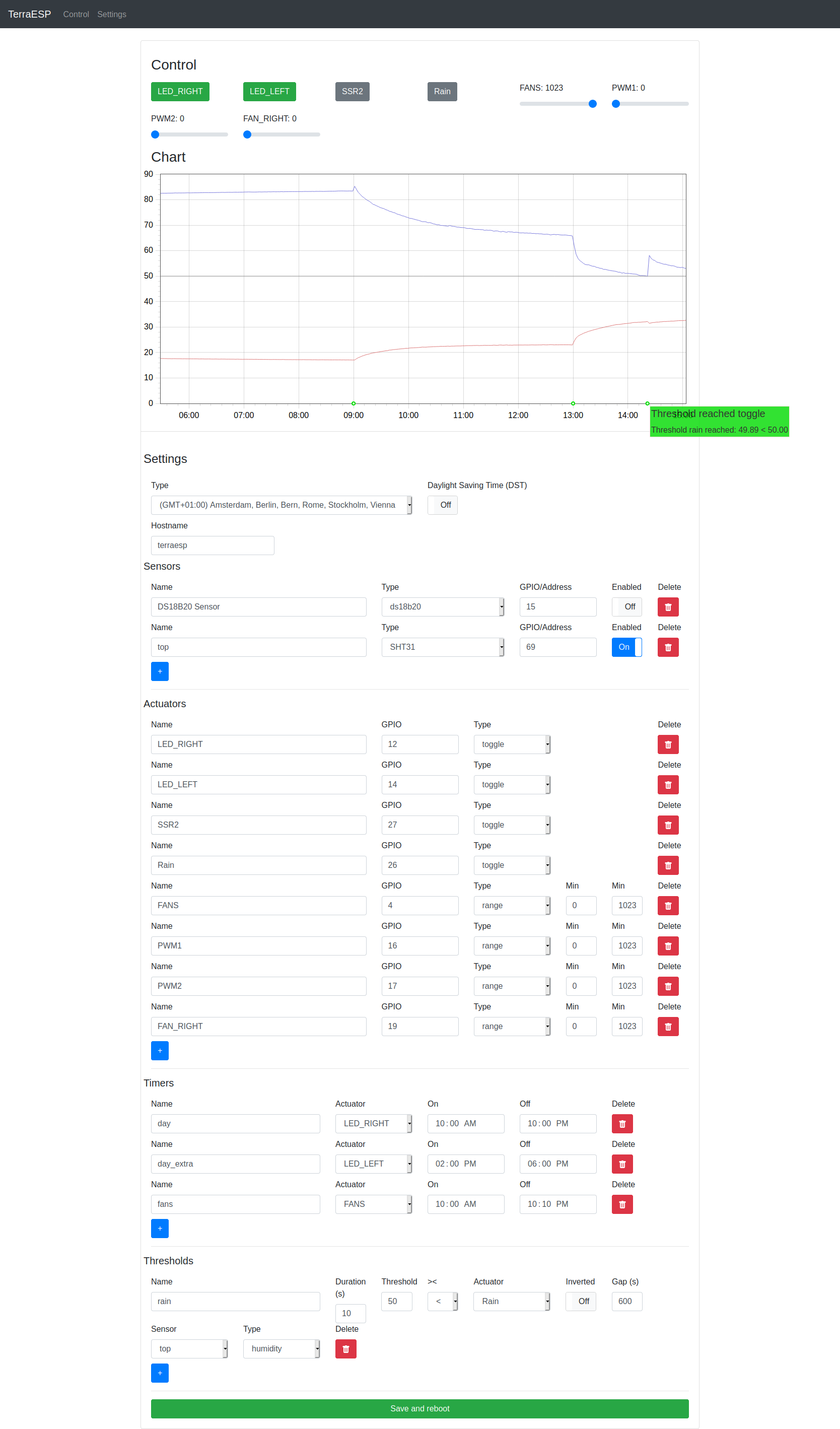
The webinterface has interactive controls to toggle relays or set PWM values to set the brightness of LEDs or fan speed.
A chart shows the measured temperatures (red) and humidity (blue) of your configured sensors and events (green) like time on, off and so on.
You can add sensors, actuators (relay, pwm), timers and thresholds in the 'settings' section.
The device creates an access point on first start. Then you can configure your WiFi and pin settings.
The WiFi password is saved without encryption on the device. Also OTA-update has default password "admin" at the moment. Change it if you want to secure your device for unauthorized updates.
Make the webinterface accessible from the internet is a very bad idea! Please use a VPN or something else to prevent a flooded terrarium ;-)
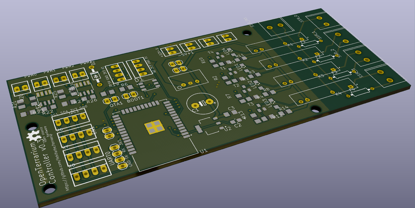
pio run -t uploadfspio lib install. The command should download all necessary libraries.error: 'timeinfo' has incomplete type just delete the Time.h header in .pio/libdeps/{ota,usb}/Time after installing the libs. The bug happens only on Windows because it's not case-sensitive and mixes the time.h header with Time.h of TimeLib library.Prototype PCB with several new features:
| Qty | Value | Footprint | References |
|---|---|---|---|
| 11 | 10k | terraesp:M1206 | R5, R6, R15, R16, R17, R18, R19, R21, R23, R25, R27 |
| 8 | 1k | terraesp:R1206 | R2, R7, R10, R13, R20, R22, R24, R26 |
| 8 | 22-23-2021 | terraesp:22-23-2021 | +12V-1, PWM0, PWM1, PWM2, PWM3, X1, X2, X3 |
| 6 | 22-23-2041 | terraesp:22-23-2041 | A0, A1, I2C1, X6, X7, X8 |
| 5 | 691212710002 | terraesp:691212710002 | SSR_0, SSR_1, SSR_2, SSR_3, SSR_IN1 |
| 5 | PINHD-1X2 | terraesp:1X02 | -5V+1, BOOT1, CON0_5V1, EN1, OTA1 |
| 4 | @HOLE0, @HOLE1, @HOLE2, @HOLE3 | ||
| 4 | 10k | terraesp:R1206 | R1, R4, R9, R12 |
| 4 | 220 | terraesp:R1206 | R3, R8, R11, R14 |
| 4 | 2A | terraesp:0207_10 | F1, F2, F3, F4 |
| 4 | BC850 | terraesp:SOT23 | T1, T2, T3, T4 |
| 4 | G3MB202PDC12 | terraesp:RELAY_G3MB202PDC12 | K1, K2, K3, K4 |
| 4 | LEDCHIPLED_1206 | terraesp:CHIPLED_1206 | LED1, LED2, LED3, LED4 |
| 2 | DMG4800LSD | terraesp:SOIC127P600X144-8 | U$2, U$3 |
| 1 | 1N4004 | terraesp:DO41-10 | D2 |
| 1 | AMS1117 | terraesp:SOT229P700X180-4N | U2 |
| 1 | C-EUC1206 | terraesp:C1206 | C3 |
| 1 | COM-11821 | terraesp:LED_COM-11821 | D1 |
| 1 | CPOL-EUE5-10.5 | terraesp:E5-10,5 | C1 |
| 1 | ESP32-WROOM-32(8MB) | terraesp:MODULE_ESP32-WROOM-32(8MB) | U1 |
| 1 | OSHWLOGOLOGO5MM | terraesp:OSHW_5MM | GOLD_ORB_SM2 |
| 1 | PINHD-1X4 | terraesp:1X04 | UART0 |
| 1 | TAJA226M010R | terraesp:CAPCP3216X180N | C2 |
| 1 | TSR1-2450 | terraesp:TSR1-2450 | U$1 |


corygrant/dingoPDM
Hardware - dingoPDM is an open source, affordable automotive PDM (Power Distribution Module). Pre-assembled and tested units are available or the design can be used to build a DIY version.

hberntsen/mhi-ac-ctrl-esp32
Control MHI Airconditioning locally using your own ESP32 series chip!


idlehandsdev/shark_bait
The files and firmware for the Shark Bait wireless pumping system.

It measures 127 × 54.3 mm and has 2 copper layers, 1.6 mm thick.
83 parts, built around the TSR 1-2450, AMS1117, DMG4800LSD and COM-11821. The full list of its parts is on this page, with links to each part's symbol and footprint where PCBKit's library has them.
From the fehlfarbe/terraesp repository on GitHub, at the commit this page was made from: the board is hardware/kicad/terraesp.kicad_pcb. PCBKit opens the board in the browser, with nothing to install.
Its repository publishes it under the MIT licence: you may reuse it on that licence's terms (keep the author's notice, and for a copyleft licence share your changes alike).