4 layers50 × 50 mm
50x50 2 Layer
UC-Aerospace/Electrical-Tut-26
2026 Avionics tutorial example boards for UC Aerospace
86 parts

 Eniemooo/Sensor-HAT
Open-hardware indoor air sensor (CO2, VOC/NOx, T/RH, light, sound): HAT for Raspberry Pi or standalone with Seeed XIAO + ESPHome. KiCad 10.
Sensor HAT is an open-source printed circuit board by Eniemooo, from the Eniemooo/Sensor-HAT repository on GitHub. It is a 4-layer board of 65 × 56 mm with 112 parts on 74 nets, routed with 1,147 tracks and 184 vias.
It is built around the SN74LV1T125DBVR-TP, SGP41-D-R4 and SHT40-AD1B-R2, with the VEML7700-TT, AP2112K-3.3TRG1 and LM66100DCK among its other parts. Its parts include 38 resistors, 27 capacitors, 13 ICs, 8 connectors and 3 diodes. It belongs with the sensors and measurement boards of this library.


Deutsch (ausführliche Anleitung): README.de.md
An open-hardware indoor-environment sensor board, designed in KiCad 10 (65 × 56 mm, 4 layers). It runs in one of two modes, never both at once:
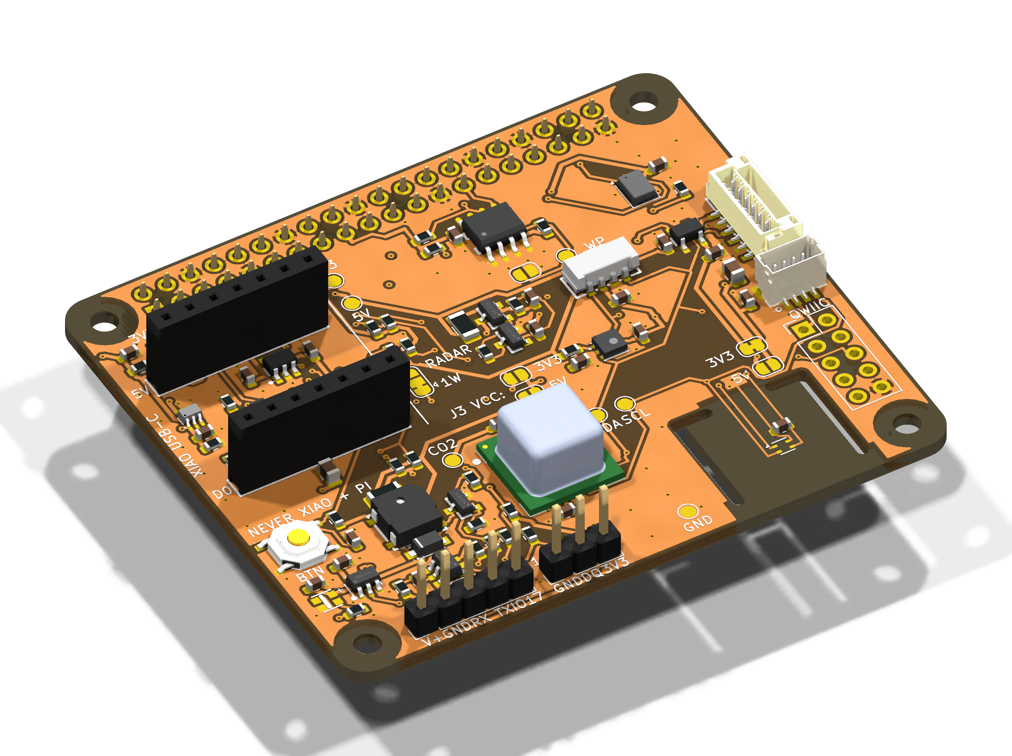
Status: the design is complete. KiCad ERC and DRC report no errors, and the ESPHome configs validate. It has not been tested in hardware yet. Build prototypes before ordering in quantity.
| Function | Part | I²C address / Pi GPIO / XIAO pin |
|---|---|---|
| CO₂ (photoacoustic, not an eCO₂ estimate) | Sensirion SCD41, own 3.3 V regulator | 0x62 |
| Temperature, humidity | Sensirion SHT40 on a milled, thermally isolated island | 0x44 |
| VOC and NOx index | Sensirion SGP41 | 0x59 |
| Ambient light (lux) | Vishay VEML7700 | 0x10 |
| Sound level | TDK ICS-43434 I²S microphone | Pi GPIO18/19/20, XIAO D1/D0/D2 |
| RGB status LED (e.g. CO₂ traffic light) | WS2812B-2020 with 5 V level shifter | Pi GPIO10, XIAO D10 |
| Button | SW1 | Pi GPIO27, XIAO D4 |
| Buzzer (passive, 4 kHz) | MLT-5020 | Pi GPIO13, XIAO D3 |
| Particulate sensor port (Sensirion SEN6x/SEN5x) | J4, JST GH 6-pin, own regulator | 0x6B / 0x69 |
| mmWave radar / UART (e.g. HLK-LD2420; LD2410C with 5 V and a re-ordered cable) | J3 | Pi GPIO14/15 (+GPIO17 OUT), XIAO D6/D7 |
| 1-Wire (e.g. DS18B20) | J2 | Pi GPIO4, XIAO D5 (JP6) |
| Qwiic / STEMMA QT | J5, JST SH 4-pin | I²C, 3.3 V |
| Spare GPIOs (Pi only) | J6, 2×5 pads, not populated | GPIO5, 12, 22–26 |
| HAT ID EEPROM | onsemi CAT24C32 | ID_SD/ID_SC, 0x50 |
All parts are in active production. The one exception is the ICS-43434 microphone: it is obsolete but still widely stocked.
Two LM66100 ideal diodes keep the two power sources apart, so no current flows from the Pi into the XIAO's USB port or the other way round.
Copy the files for your XIAO from software/esphome/: sensor-hat-xiao-s3.yaml, -c3.yaml or -c6.yaml. You always need sensor-hat-common.yaml and a secrets.yaml as well. Start from secrets.yaml.example and fill in:
openssl rand -base64 32), which also protects OTA updatesThe placeholders in the template are rejected by esphome config on purpose. With more than one board, give each its own name: in the substitutions, for example sensor-hat-kitchen.
Flash the XIAO once over USB without the board attached. Then plug it into J7/J8 with the USB-C facing outwards. Later updates go over Wi-Fi. When you add the device in Home Assistant, it asks for the API encryption key.
Calibrate the readings:
altitude_compensation to your altitudeoffset against a reference thermometerNotes:
restore_mode: ALWAYS_ON for the antenna_select switch in sensor-hat-xiao-c6.yaml (GPIO14 high selects the U.FL socket).software/config.txt.snippet to /boot/firmware/config.txt and reboot.software/sensor_test.py. The pip packages it needs are listed at the top of the file.software/eeprom_settings.txt and the German README.| Jumper | As delivered | Function |
|---|---|---|
| JP1 / JP3 | open | J3 supply: JP1 = 3.3 V, JP3 = 5 V. Never bridge both. |
| JP4 / JP5 | JP4 closed | J4 supply: JP4 = 3.3 V for SEN6x, JP5 = 5 V for SEN5x. 5 V destroys a SEN6x. Cut JP4, check with a multimeter that it is open, then bridge JP5. |
| JP6 | 1-2 closed | XIAO D5 = 1-Wire (J2). For the radar OUT pin, cut 1-2 and bridge 2-3. |
| JP2 | open | Bridge it to make the HAT EEPROM writable (Pi only). |
sensor-hat-radar-ld2410.yaml for the LD2410/LD2410C and the ld2420 component for the LD2420. ESPHome has no UART support for the LD2410S, so only its OUT pin works (JP6 2-3).production/ holds JLCPCB files: Gerber zip, BOM and CPL in two variants. The "komplett" variant also has JLCPCB solder the through-hole headers and XIAO sockets. The 40-pin Pi socket J1 is always soldered by hand.
Recommended settings:
The complete order remark is in the German README, section "Bei JLCPCB bestellen".
Estimated landed cost per assembled board for the SMD-only variant, incl. 19 % German VAT. You buy and solder the headers J1–J3, J7 and J8 yourself. python3 -I scripts/cost.py recalculates it with live part prices:
| Boards | 2 | 5 | 20 | 50 | 100 |
|---|---|---|---|---|---|
| per board | ~125 € | ~77 € | ~50 € | ~42 € | ~37 € |
Small orders are expensive because of fixed setup fees, so a community group buy at cost is planned (German: docs/Sammelbestellung.md).
| Path | Contents |
|---|---|
Sensor-HAT.kicad_pro/.kicad_sch/.kicad_pcb | KiCad 10 project |
production/ | Gerber, BOM, CPL for JLCPCB |
docs/ | schematic and assembly PDFs, renders, group-buy documents (German) |
software/ | ESPHome configs, Pi config, test script, EEPROM settings |
lib/ | project symbols and footprints (3D models: see below) |
scripts/ | the generator: design.py (parts and nets) and placement.py are the single source of truth; build.sh regenerates schematic and board and autoroutes them |
pip install easyeda2kicad
python3 -I scripts/fetch_3d_models.py .   # LCSC 3D models, only needed for 3D view, renders, STEP
export FREEROUTING_JAR=/path/to/freerouting-2.5.0.jar
scripts/build.sh                          # schematic + ERC, board, autorouting, GND repair, DRC
python3 -I scripts/export.py .            # Gerber, BOM, CPL, PDFs, renders, STEP
Requirements:
The scripts expect KiCad on macOS at ~/Applications/KiCad/KiCad.app. For other installations, change the paths at the top of build.sh, kicadlib.py, gen_pcb.py, route.py, cleanup.py and export.py. If your Java is not Homebrew's openjdk, run export JAVA=$(which java) before build.sh.
scripts/design.py and scripts/placement.py, production files, PDFs, renders): CERN-OHL-S-2.0Source: https://github.com/Eniemooo/Sensor-HAT. Which licence covers which file is listed in LICENSE.md. Some symbols and footprints come from the LCSC/EasyEDA library, which has no licence of its own. These parts, and the trademarks, are listed in NOTICE.md.
Raspberry Pi is a trademark of Raspberry Pi Ltd. This project is not affiliated with Raspberry Pi Ltd or Seeed Studio. No warranty.
| Qty | Value | Footprint | References |
|---|---|---|---|
| 14 | 100 | Resistor_SMD:R_0603_1608Metric | R16, R20, R22, R33, R34, R35, R36, R37, R38, R39, R40, R41, R42, R43 |
| 12 | 1uF | Capacitor_SMD:C_0603_1608Metric | C1, C2, C3, C14, C15, C17, C18, C27, C28, C29, C30, C31 |
| 10 | 100nF | Capacitor_SMD:C_0603_1608Metric | C5, C6, C8, C9, C10, C16, C20, C23, C24, C26 |
| 9 | 100k | Resistor_SMD:R_0603_1608Metric | R4, R7, R11, R13, R14, R23, R29, R30, R32 |
| 4 | 10k | Resistor_SMD:R_0603_1608Metric | R12, R15, R19, R31 |
| 4 | 1k | Resistor_SMD:R_0603_1608Metric | R5, R8, R9, R10 |
| 4 | M2.5 | MountingHole:MountingHole_2.7mm_M2.5 | MH1, MH2, MH3, MH4 |
| 3 | 4.7k | Resistor_SMD:R_0603_1608Metric | R1, R26, R27 |
| 3 | AP2112K-3.3 | SensorHAT:SOT-25-5_L2.9-W1.6-P0.95-LS2.8-BL | U5, U6, U9 |
| 2 | 10uF | Capacitor_SMD:C_0603_1608Metric | C4, C13 |
| 2 | 10uF 25V | Capacitor_SMD:C_0805_2012Metric | C11, C12 |
| 2 | 3.9k | Resistor_SMD:R_0603_1608Metric | R2, R3 |
| 2 | AO3400A | SensorHAT:SOT-23_L2.9-W1.3-P1.90-LS2.4-BR | Q2, Q3 |
| 2 | LM66100 | SensorHAT:SC-70-6_L2.0-W1.3-P0.65-LS2.1-BL | U14, U15 |
| 1 | +3V3 | TestPoint:TestPoint_Pad_D1.5mm | TP2 |
| 1 | +3V3_CO2 | TestPoint:TestPoint_Pad_D1.5mm | TP3 |
| 1 | +5V | TestPoint:TestPoint_Pad_D1.5mm | TP1 |
| 1 | 0.5A PTC | Fuse:Fuse_1206_3216Metric | F1 |
| 1 | 1-Wire GND/DQ/3V3 | Connector_PinHeader_2.54mm:PinHeader_1x03_P2.54mm_Vertical | J2 |
| 1 | 1N4148W | SensorHAT:SOD-123F_L2.7-W1.6-LS3.8-RD | D2 |
| 1 | 22uF 25V | Capacitor_SMD:C_0805_2012Metric | C19 |
| 1 | 33 0.5W 1206 | Resistor_SMD:R_1206_3216Metric | R21 |
| 1 | 4.7 | Resistor_SMD:R_0603_1608Metric | R28 |
| 1 | 74LV1T125 | SensorHAT:SOT-23-5_L3.0-W1.7-P0.95-LS2.8-BL | U12 |
| 1 | AO3401A | SensorHAT:SOT-23_L2.9-W1.3-P1.90-LS2.4-BR | Q1 |
| 1 | BAV70 | SensorHAT:SOT-23-3_L3.0-W1.7-P0.95-LS2.9-BR | D3 |
| 1 | Button | SensorHAT:SW-SMD_4P-L5.1-W5.1-P3.70-LS6.5-TL_H1.5 | SW1 |
| 1 | CAT24C32 | SensorHAT:SOIC-8_L5.0-W4.0-P1.27-LS6.0-BL | U4 |
| 1 | D5 = 1-Wire | radar OUT | Jumper:SolderJumper-3_P1.3mm_Bridged12_RoundedPad1.0x1.5mm | JP6 |
| 1 | EEPROM write enable | Jumper:SolderJumper-2_P1.3mm_Open_RoundedPad1.0x1.5mm | JP2 |
| 1 | EE_WP | TestPoint:TestPoint_Pad_D1.5mm | TP5 |
| 1 | GND | TestPoint:TestPoint_Pad_D1.5mm | TP4 |
| 1 | GPIO expansion (DNP) | Connector_PinHeader_2.54mm:PinHeader_2x05_P2.54mm_Vertical | J6 |
| 1 | I2C_SCL | TestPoint:TestPoint_Pad_D1.5mm | TP7 |
| 1 | I2C_SDA | TestPoint:TestPoint_Pad_D1.5mm | TP6 |
| 1 | ICS-43434 | Sensor_Audio:InvenSense_ICS-43434-6_3.5x2.65mm | U3 |
| 1 | J3 VCC = 3V3 | Jumper:SolderJumper-2_P1.3mm_Open_RoundedPad1.0x1.5mm | JP1 |
| 1 | J3 VCC = 5V | Jumper:SolderJumper-2_P1.3mm_Open_RoundedPad1.0x1.5mm | JP3 |
| 1 | MLT-5020 4kHz | SensorHAT:BUZ-SMD_L5.0-W5.5-P4.60 | LS1 |
| 1 | PM VCC = 3V3 | Jumper:SolderJumper-2_P1.3mm_Bridged_RoundedPad1.0x1.5mm | JP4 |
| 1 | PM VCC = 5V | Jumper:SolderJumper-2_P1.3mm_Open_RoundedPad1.0x1.5mm | JP5 |
| 1 | PM sensor (SEN6x/SEN5x) | SensorHAT:CONN-SMD_6P-P1.25_BM06B-GHS-TBT-LF-SN-N | J4 |
| 1 | Qwiic / STEMMA QT | SensorHAT:CONN-SMD_BM04B-SRSS-TB | J5 |
| 1 | RPi GPIO 2x20 | Connector_PinSocket_2.54mm:PinSocket_2x20_P2.54mm_Vertical | J1 |
| 1 | SCD41-D-R2 | SensorHAT:LGA-20_L10.1-W10.1-P1.25-TL_SCD41-D-R2 | U1 |
| 1 | SGP41 | SensorHAT:DFN-6_L2.4-W2.4-P0.80-TL-EP | U13 |
| 1 | SHT40 | SensorHAT:SHT4x_DFN-4_1.5x1.5mm_P0.8mm_NoCentralPad | U2 |
| 1 | SRV05-4 | SensorHAT:SOT-23-6_L2.9-W1.6-P0.95-LS2.8-BR | U8 |
| 1 | UART (e.g. PMS5003) | Connector_PinHeader_2.54mm:PinHeader_1x05_P2.54mm_Vertical | J3 |
| 1 | VEML7700-TT | SensorHAT:SENSOR-SMD_EML7700-TT | U7 |
| 1 | WS2812B-2020 | SensorHAT:LED-SMD_4P-L2.2-W2.0-P1.00_WS2815C-2020-4P | D1 |
| 1 | XIAO 5V-D7 | SensorHAT:HDR-TH_7P-P2.54-V-F | J8 |
| 1 | XIAO D0-D6 | SensorHAT:HDR-TH_7P-P2.54-V-F | J7 |
UC-Aerospace/Electrical-Tut-26
2026 Avionics tutorial example boards for UC Aerospace

sequoia-hope/ultraroute
PCB autorouting experiments around copperroute: route jobs, leaderboards, board morphing


3351666087/solar-vest
Self-powered solar-harvesting wearable ECG vest: PCBs, 3D-printed enclosures, vest patterns, simulation and an interactive 3D explorer

JoeMighty/opentouch-s3
A modern remake of the Bare Conductive Touch Board: 12 capacitive touch electrodes, MP3/WAV/MIDI audio, and now WiFi, Bluetooth LE, USB-C, a proper LiPo power path, a fuel gauge, line-in, MIDI out, Qwiic and an RGB LED.


PTR-projects/PTR_mini_hardware
Welcome to the KPPTR-hardware repository! This repository contains the design files for the hardware components used in the KPPTR project.

desanv01/Flight-Controller-V1
STM32H743 flight controller: staged design, six-layer PCB implementation, manufacturing data and engineering history.
It measures 65 × 56 mm and has 4 copper layers, 1.6 mm thick.
112 parts, built around the SN74LV1T125DBVR-TP, SGP41-D-R4, SHT40-AD1B-R2 and VEML7700-TT. The full list of its parts is on this page, with links to each part's symbol and footprint where PCBKit's library has them.
From the Eniemooo/Sensor-HAT repository on GitHub, at the commit this page was made from: the board is Sensor-HAT.kicad_pcb and its schematic Sensor-HAT.kicad_sch. PCBKit opens the board in the browser, with nothing to install.
Its repository states no licence, so its author keeps all rights: ask Eniemooo before reusing the design.