4 layers99 × 70 mm

 JoeMighty/opentouch-s3
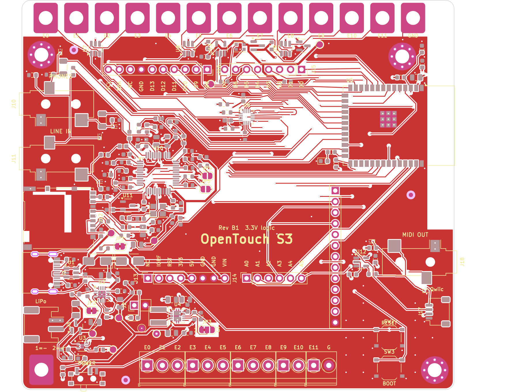
A modern remake of the Bare Conductive Touch Board: 12 capacitive touch electrodes, MP3/WAV/MIDI audio, and now WiFi, Bluetooth LE, USB-C, a proper LiPo power path, a fuel gauge, line-in, MIDI out, Qwiic and an RGB LED.
Opentouch s3 is an open-source printed circuit board by JoeMighty, from the JoeMighty/opentouch-s3 repository on GitHub. It is a 4-layer board of 100 × 90 mm with 185 parts on 116 nets, routed with 1,670 tracks and 361 vias.
It is built around the SN74LV1T125DBVR-TP, ESP32-S3-WROOM-1-N16R8 and MPR121QR2, with the SRV05-4-P-T7, BQ24074RGTR and MAX17048G+T10 among its other parts. Its parts include 54 resistors, 44 capacitors, 15 connectors, 10 diodes and 9 ICs. It belongs with the radio and wireless and audio and music boards and the ESP32 boards of this library.


Rev B1 · an open hardware remake of the Bare Conductive Touch Board
















Project page · Schematic · Fab files · Order it
A modern remake of the Bare Conductive Touch Board: 12 capacitive touch electrodes, MP3/WAV/MIDI audio, and now WiFi, Bluetooth LE, USB-C, a proper LiPo power path, a fuel gauge, line-in, MIDI out, Qwiic and an RGB LED.
Based on the Bare Conductive Touch Board open hardware files (CC BY-SA 3.0, https://github.com/BareConductive/touch_board_cad_files). This is an independent adaptation, not affiliated with or endorsed by Bare Conductive, and released under the same licence (CC BY-SA 3.0).
Status: Rev B1, design complete, not yet fabricated or tested. Read "Before you order" below.
| Path | What it is |
|---|---|
hardware/kicad/ | KiCad 7 project: hierarchical schematic (5 sheets), 4-layer PCB |
hardware/kicad/lib/ | Project symbols (VS1053B, MAX17048, electrode pad) and the edge electrode footprint |
hardware/fab/OpenTouch_S3_gerbers_JLCPCB.zip | Gerbers + drill files, upload this to JLCPCB |
hardware/fab/OpenTouch_S3_BOM_JLCPCB.csv | Assembly BOM with LCSC part numbers (57 lines, 145 placed parts) |
hardware/fab/OpenTouch_S3_CPL_JLCPCB.csv | Pick-and-place file (rotations pre-corrected for JLCPCB) |
hardware/fab/OpenTouch_S3_BOM_full.csv | Full BOM including hand-fit (DNP) parts and notes |
hardware/fab/OpenTouch_S3_schematic.pdf | Schematic / wiring diagram |
hardware/gen/ | Python scripts that generate the schematic and PCB from one netlist (design.py) |
docs/index.html | Project page for GitHub Pages |
docs/renders/ | Board renders: top, bottom, inner GND plane, inner 3V3 plane, routing |
To publish the project page: repo Settings > Pages > Source: Deploy from a branch > Branch: main, folder /docs > Save.
It will appear at https://<your-username>.github.io/opentouch-s3/.
| Function | GPIO | Header |
|---|---|---|
| I2C SDA / SCL (MPR121, MAX17048, Qwiic) | IO8 / IO9 | D2 / D3 |
| MPR121 IRQ | IO10 | D4 |
| SPI MOSI / SCK / MISO (VS1053 + microSD) | IO11 / IO12 / IO13 | D11 / D13 / D12 |
| microSD CS | IO14 | |
| VS1053 XCS / XDCS / DREQ / XRESET | IO15 / IO16 / IO17 / IO46 | |
| Serial MIDI into VS1053 (close JP5) | IO18 | |
| MIDI OUT (UART TX) | IO47 | |
| RGB LED (WS2812B) | IO48 | |
| L LED | IO45 | |
| USB power present (PGOOD, active low) | IO21 | |
| A0 A1 A2 A3 A4 A5 (ADC1, also ESP32 touch pins) | IO1 IO2 IO4 IO5 IO6 IO7 | A0-A5 |
| D0 RX / D1 TX | IO44 / IO43 | D0 / D1 |
| D5 D6 D7 D8 D9 D10 | IO3 IO41 IO42 IO38 IO39 IO40 | |
| BOOT button | IO0 |
Strapping pins are handled: IO0 has the BOOT button, IO45 drives an LED to ground (low at boot), IO46 holds the VS1053 in reset through a 100 k pull-down (low at boot), IO3 is only used as a plain digital pin.
| Jumper | Default | Change |
|---|---|---|
| JP1 | bridged: 500 mA charge | cut for 250 mA (small cells under 500 mAh) |
| JP2 | bridged: no battery thermistor | cut when you fit a 10 k NTC to J2 |
| JP3 | 1-2: power-save mode | 2-3: forced PWM, lowest audio noise, slightly higher idle current |
| JP4 | open | close to boot the VS1053 into real-time MIDI synth mode |
| JP5 | open | close to send serial MIDI from IO18 into the VS1053 |
OpenTouch_S3_gerbers_JLCPCB.zip. Choose 4 layers, 1.6 mm, ENIG surface finish (for the touch pads), any mask colour.design.py netlist agree on all 609 pads. Some routes are longer than a hand layout would be, so it is worth a look,
especially the 3.3 V buck-boost loop (U4, L1, C8-C10) and the USB D+/D- pair.5V header pin is USB VBUS. Don't power the board through it; use VIN (4.5-10 V) instead.Arduino IDE with the Espressif ESP32 core (board: "ESP32S3 Dev Module", USB CDC On Boot enabled, PSRAM "OPI PSRAM", flash 16 MB). Libraries that work with this pin map:
Adafruit_VS1053_FilePlayer player(46, 15, 16, 17, 14); (reset, CS, DCS, DREQ, card CS).
Call SPI.begin(12, 13, 11) first so the ESP32 uses this board's SPI pins.Serial1 with TX mapped to IO47 (31250 baud).Touch Board sketches port mostly by changing pin numbers: the MPR121 address and electrode numbering are unchanged.
hardware/gen/design.py is the single source of truth (every part, value, LCSC number and pin-to-net mapping).
make_sch.py writes the schematic, make_pcb.py places the board, pipeline.sh runs autorouting and repairs,
export_fab.py writes the JLCPCB files. The scripts need KiCad 7's Python module, Java and Freerouting 1.9, and
use absolute paths from the machine they were written on, so adjust the paths at the top of each script first.
CC BY-SA 3.0, the same licence as the original Touch Board design. See LICENSE.md and NOTICE.md.
| Qty | Value | Footprint | References |
|---|---|---|---|
| 19 | 100nF | C_0603_1608Metric | C3, C11, C12, C14, C16, C17, C22, C23, C24, C25, C26, C29, C30, C32, C41, C42 +3 |
| 18 | 100k | R_0603_1608Metric | R13, R22, R23, R24, R25, R26, R27, R28, R29, R31, R32, R33, R34, R41, R42, R48 +2 |
| 11 | 10k | R_0603_1608Metric | R7, R9, R10, R11, R15, R16, R19, R30, R39, R40, R49 |
| 7 | 10uF | C_0805_2012Metric | C6, C8, C9, C10, C27, C28, C40 |
| 7 | 1uF | C_0603_1608Metric | C15, C20, C21, C31, C38, C39, C44 |
| 6 | ESD9B5.0ST5G | D_SOD-923 | D6, D7, D8, D9, D10, D11 |
| 3 | 100 | R_0603_1608Metric | R12, R43, R44 |
| 3 | 10nF | C_0603_1608Metric | C35, C36, C37 |
| 3 | 1k | R_0603_1608Metric | R8, R14, R17 |
| 3 | 20 | R_0603_1608Metric | R36, R37, R38 |
| 3 | 47k | R_0603_1608Metric | R45, R46, R47 |
| 3 | Fiducial | Fiducial_1mm_Mask2mm | FID1, FID2, FID3 |
| 3 | KF350-3.5-3P | TerminalBlock_Phoenix_PT-1,5-3-3.5-H_1x03_P3.50mm_Horizontal | J4, J5, J6 |
| 3 | M3 | MountingHole_3.2mm_M3_Pad_Via | H1, H2, H3 |
| 3 | SRV05-4 | SOT-23-6 | U7, U8, U9 |
| 2 | 100uF | C_1206_3216Metric | C33, C34 |
| 2 | 10pF | C_0603_1608Metric | C18, C19 |
| 2 | 1M | R_0603_1608Metric | R3, R35 |
| 2 | 22uF | C_0805_2012Metric | C4, C13 |
| 2 | 3.6k | R_0603_1608Metric | R5, R6 |
| 2 | 33 | R_0603_1608Metric | R51, R54 |
| 2 | 4.7k | R_0603_1608Metric | R20, R21 |
| 2 | 5.1k | R_0603_1608Metric | R1, R2 |
| 2 | AO3401A | SOT-23 | Q1, Q2 |
| 2 | GND | ElectrodePad_Edge_5.6x7mm_D3.2mm | E13, E14 |
| 2 | KF350-3.5-2P | TerminalBlock_Phoenix_PT-1,5-2-3.5-H_1x02_P3.50mm_Horizontal | J7, J8 |
| 2 | SN74LV1T125DBVR | SOT-23-5 | U12, U13 |
| 2 | SS54 | D_SMA | D1, D2 |
| 1 | +1V8 | TestPoint_Pad_D1.5mm | TP7 |
| 1 | +3V3 | TestPoint_Pad_D1.5mm | TP2 |
| 1 | 1.1A | Fuse_1206_3216Metric | F1 |
| 1 | 1.5k | R_0603_1608Metric | R4 |
| 1 | 1.5uH | L_Changjiang_FNR4020S | L1 |
| 1 | 10 | R_0603_1608Metric | R50 |
| 1 | 12.288MHz | Crystal_SMD_3225-4Pin_3.2x2.5mm | Y1 |
| 1 | 2N7002 | SOT-23 | Q3 |
| 1 | 4.7nF | C_0603_1608Metric | C1 |
| 1 | 4.7uF | C_0805_2012Metric | C2 |
| 1 | 600R@100MHz | L_0805_2012Metric | FB1 |
| 1 | 75k | R_0603_1608Metric | R18 |
| 1 | ANALOG | PinSocket_1x06_P2.54mm_Vertical | J14 |
| 1 | BOOT | SW_Push_1P1T_XKB_TS-1187A | SW3 |
| 1 | BQ24074RGTR | VQFN-16-1EP_3x3mm_P0.5mm_EP1.6x1.6mm | U2 |
| 1 | CHG 500mA | SolderJumper-2_P1.3mm_Bridged_RoundedPad1.0x1.5mm | JP1 |
| 1 | D0-D7 | PinSocket_1x08_P2.54mm_Vertical | J15 |
| 1 | D8-D13 | PinSocket_1x10_P2.54mm_Vertical | J16 |
| 1 | E0 | ElectrodePad_Edge_5.6x7mm_D3.2mm | E1 |
| 1 | E1 | ElectrodePad_Edge_5.6x7mm_D3.2mm | E2 |
| 1 | E10 | ElectrodePad_Edge_5.6x7mm_D3.2mm | E11 |
| 1 | E11 | ElectrodePad_Edge_5.6x7mm_D3.2mm | E12 |
| 1 | E2 | ElectrodePad_Edge_5.6x7mm_D3.2mm | E3 |
| 1 | E3 | ElectrodePad_Edge_5.6x7mm_D3.2mm | E4 |
| 1 | E4 | ElectrodePad_Edge_5.6x7mm_D3.2mm | E5 |
| 1 | E5 | ElectrodePad_Edge_5.6x7mm_D3.2mm | E6 |
| 1 | E6 | ElectrodePad_Edge_5.6x7mm_D3.2mm | E7 |
| 1 | E7 | ElectrodePad_Edge_5.6x7mm_D3.2mm | E8 |
| 1 | E8 | ElectrodePad_Edge_5.6x7mm_D3.2mm | E9 |
| 1 | E9 | ElectrodePad_Edge_5.6x7mm_D3.2mm | E10 |
| 1 | ESP32-S3-WROOM-1-N16R8 | ESP32-S3-WROOM-1 | U5 |
| 1 | FG_ALRT | TestPoint_Pad_D1.5mm | TP6 |
| 1 | GND | TestPoint_Pad_D1.5mm | TP4 |
| 1 | GREEN | LED_0603_1608Metric | D4 |
| 1 | HEADPHONE | Jack_3.5mm_CUI_SJ-3523-SMT_Horizontal | J10 |
| 1 | LED DOUT | TestPoint_Pad_D1.5mm | TP8 |
| 1 | LED VDD | TestPoint_Pad_D1.5mm | TP9 |
| 1 | LINE IN | Jack_3.5mm_CUI_SJ-3523-SMT_Horizontal | J11 |
| 1 | LiPo JST-PH | JST_PH_S2B-PH-SM4-TB_1x02-1MP_P2.00mm_Horizontal | J3 |
| 1 | MAX17048G+T10 | TDFN-8-1EP_2x2mm_P0.5mm_EP0.8x1.2mm | U3 |
| 1 | MIDI OUT | Jack_3.5mm_CUI_SJ-3523-SMT_Horizontal | J18 |
| 1 | MIDI>VS | SolderJumper-2_P1.3mm_Open_RoundedPad1.0x1.5mm | JP5 |
| 1 | MPR121QR2 | UQFN-20_3x3mm_P0.4mm | U6 |
| 1 | NO NTC | SolderJumper-2_P1.3mm_Bridged_RoundedPad1.0x1.5mm | JP2 |
| 1 | NTC 10k | PinHeader_1x02_P2.54mm_Vertical | J2 |
| 1 | POWER | PinSocket_1x08_P2.54mm_Vertical | J13 |
| 1 | POWER | SW_SPDT_PCM12 | SW1 |
| 1 | PS/PWM | SolderJumper-3_P1.3mm_Bridged12_RoundedPad1.0x1.5mm_NumberLabels | JP3 |
| 1 | Qwiic | JST_SH_SM04B-SRSS-TB_1x04-1MP_P1.00mm_Horizontal | J17 |
| 1 | RED | LED_0603_1608Metric | D5 |
| 1 | RESET | SW_Push_1P1T_XKB_TS-1187A | SW2 |
| 1 | RT-MIDI | SolderJumper-2_P1.3mm_Open_RoundedPad1.0x1.5mm | JP4 |
The 173 most common of 185 parts.

dudgeon/count-fidget
A lightweight, rechargeable two-key fidget that counts clicks, resets with a second key, and remembers its count while asleep or unpowered. Designed for a home-printed enclosure and professionally assembled electronics.

Eniemooo/Sensor-HAT
Open-hardware indoor air sensor (CO2, VOC/NOx, T/RH, light, sound): HAT for Raspberry Pi or standalone with Seeed XIAO + ESPHome. KiCad 10.


xmyoot/esp32c6-ble-sensor-coin-cell
Ultra-compact 4-layer circular BLE sensor pod with ESP32-C6, CR2032 coin-cell power and environmental sensors

ilomon10/embedded-totalizer-hour-meter
ESP32 engine hour meter & totalizer: firmware, SensorFrame protocol, Node host tools, KiCad PCB and a Deno device simulator
It measures 100 × 90 mm and has 4 copper layers, 1.6 mm thick.
185 parts, built around the SN74LV1T125DBVR-TP, ESP32-S3-WROOM-1-N16R8, MPR121QR2 and SRV05-4-P-T7. The full list of its parts is on this page, with links to each part's symbol and footprint where PCBKit's library has them.
From the JoeMighty/opentouch-s3 repository on GitHub, at the commit this page was made from: the board is hardware/kicad/OpenTouch_S3.kicad_pcb and its schematic hardware/kicad/OpenTouch_S3.kicad_sch. PCBKit opens the board in the browser, with nothing to install.
Its repository states no licence, so its author keeps all rights: ask JoeMighty before reusing the design.