2 layers42 × 39.5 mm

 dagroe/zigbee-rotary-dimmer-switch24
a rotary dimmer switch
Dimmer esp v1 main is an open-source printed circuit board by dagroe, from the dagroe/zigbee-rotary-dimmer-switch repository on GitHub, published under the MIT licence. It is a 4-layer board of 44 × 48.1 mm with 59 parts on 52 nets, routed with 829 tracks and 80 vias.
It is built around the ESP32-C6-MINI-1-N4, SN74LV1T125DBVR-TP and IRM-02-5S, with the PEC11S-929K-S0015, SGM2212-3.3XKC3G/TR and 0603B103K500NT among its other parts. Its parts include 20 resistors, 12 capacitors, 6 diodes, 5 ICs and 4 switches. It belongs with the ESP32 and RISC-V boards of this library.


A Zigbee dimmer switch with a tactile feeling like classic rotary dimmers that seamlessly integrates with your existing switch and socket design lines (e.g. Gira System 55).
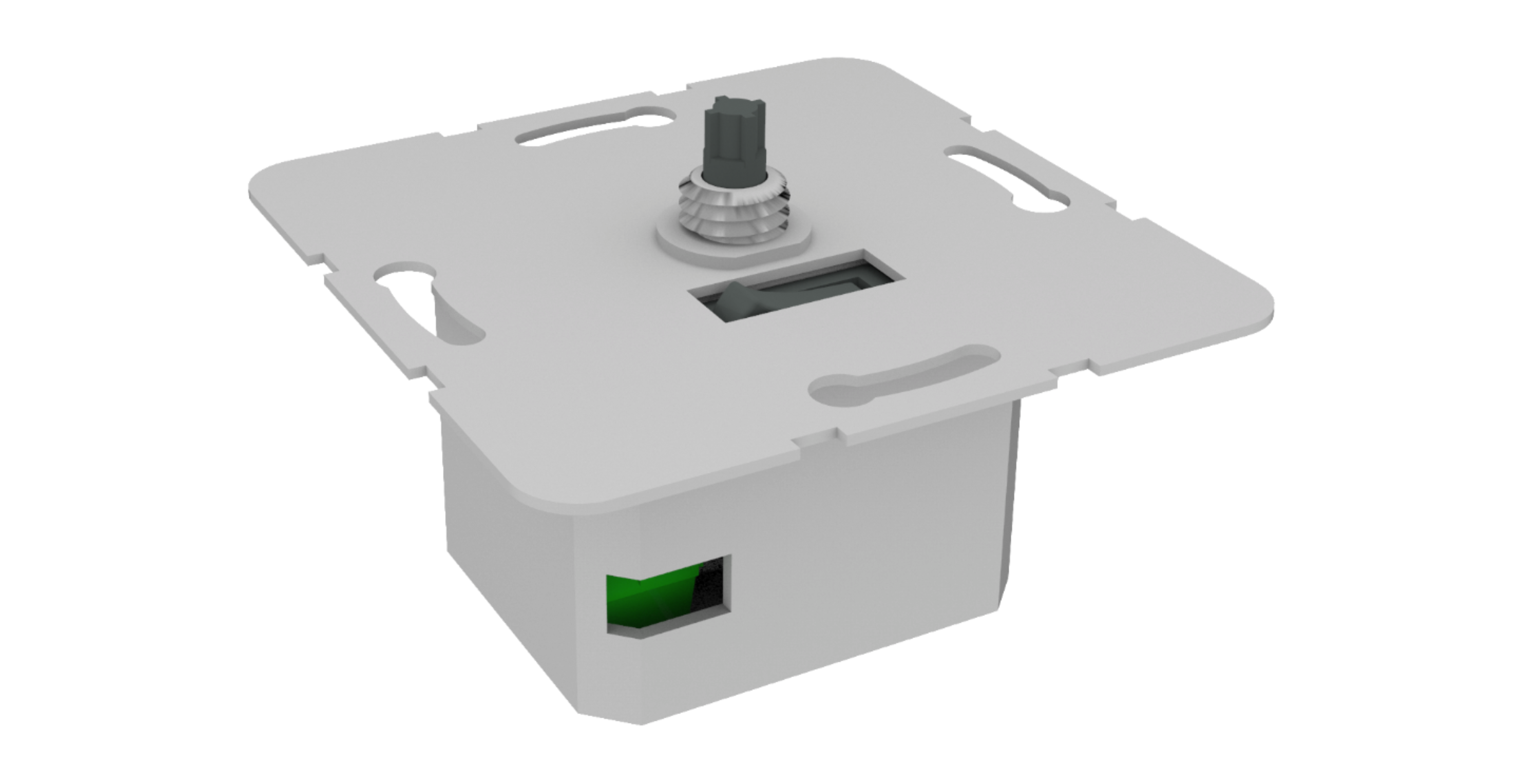 | 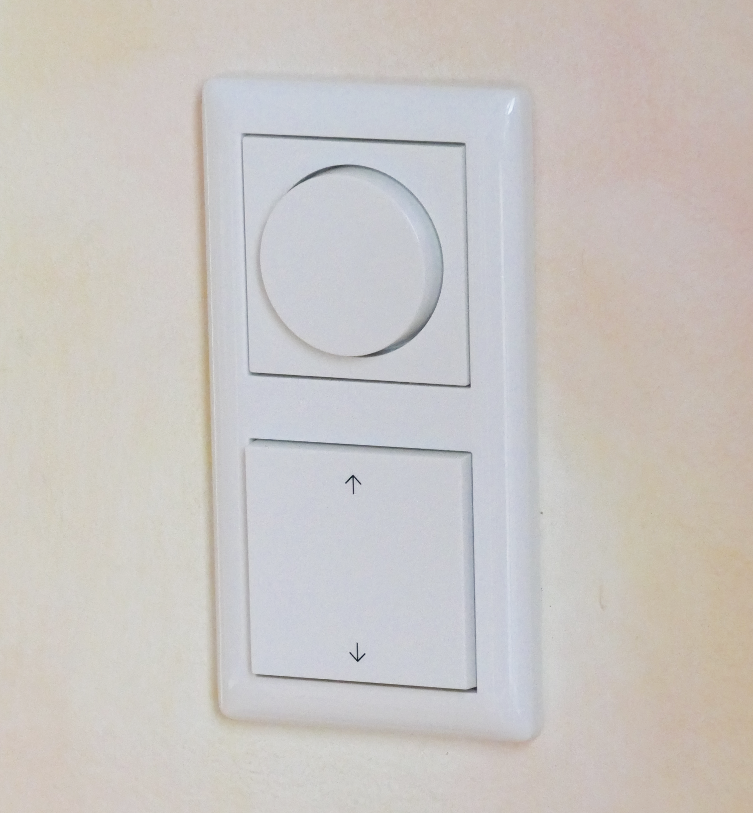 |
|---|
The goal of this dimmer switch is to
Also nice to have:
TL;DR; I couldn't find one to fit my use case, so I decided to build my own.
When I moved into my new home I already had many Philips Hue Bulbs and classic Hue dimmer switches (the on with the four buttons) to control the lights. However, those didn't integrate well with my Gira System 55 outlets, switches, frames, etc. even when using fancy adapters (https://www.samotech.co.uk/products/philips-hue-dimmer-frame-cover-light-switch/) And I was also a big fan of using a rotary knob for dimming lights, since it is just more convenient.
So why didn't I use available rotary zigbee dimmers? Basically all dimmers I found are "real" dimmers, in the sense that they expect to control a load (classic dimmable bulb) or simply don't fit into the 55mm Gira system.
Since I though "well, it can't be that hard to hook up a rotary encoder to a Zigbee chip", I set out to build a rotary dimmer switch myself.
A working second prototype is built around the ESP32-C6. It joins any standard Zigbee coordinator (zigbee2mqtt, Home Assistant ZHA, deCONZ, …) as a mains-powered Zigbee router and controls bound smart lights with a single rotary knob. Hardware, firmware, and enclosure design files are all in this repository. It is a DIY prototype, not a finished product — see Help wanted.
| Input | Action |
|---|---|
| Rotate knob | Brightness up / down (bound lights) |
| Push knob — short tap | Toggle on / off |
| Push knob — hold | Off |
| Push and rotate | Color temperature (warm / cool) |
| Relay button — tap | Cut / restore the 230V outlet (works even with no network) |
| External encoder (optional) | Second, independently bindable dimmer — same controls as the knob |
| External wall switch (optional) | Toggle on / off for its own independently bound light |
| Commission button — tap | Pair (start network steering) |
| Commission button — hold ~5 s | Factory reset (yellow warning while holding, red on reset) |
LED feedback: green = joined · solid red = not connected · white blink = command sent · red blink = command dropped (not joined) · blue blink = relay toggled · yellow = pairing / reset warning.
Built with ESP-IDF and the esp-zigbee-sdk. From firmware/:
idf.py set-target esp32c6
idf.py build
idf.py -p <PORT> flash monitor
After the first flash, firmware updates are delivered over the air (standard Zigbee OTA, with automatic rollback of a bad image). The single source of truth for the version is firmware/main/version.h.
hardware/ — KiCad schematics, PCB, and exported gerbers/3D models.firmware/ — ESP-IDF project (firmware/docs/OTA.md, firmware/z2m/README.md, firmware/TODO.md).enclosure/ — printable enclosure / knob design files.The dimmer joins any standard Zigbee coordinator and exposes four endpoints: the on-board controller (endpoint 1) that sends on/off, brightness and color commands to bound lights, the on-board 230V relay (endpoint 2) to switch the connected lamp socket directly, and the two optional daughterboard ports — an external encoder (endpoint 3, a second dimmer) and an external wall switch (endpoint 4). Each controller endpoint is bound independently, so they act as separate controllers sharing one device card. It also implements the standard Zigbee OTA Upgrade cluster, so firmware updates are delivered over the air. To add the device to zigbee2mqtt and receive OTA updates from this repo, follow firmware/z2m/README.md. Firmware-side OTA details (partitioning, rollback) are in firmware/docs/OTA.md.
My prototype is working but I see a lot of potential for improvement. Since I am mostly a software engineer with limited knowledge of electronics, I am looking for other interested in taking this project further. You can find me on discord here: https://discord.gg/CjbDc5nPja or checkout the discussion here: https://community.home-assistant.io/t/diy-zigbee-rotary-wall-dimmer/681751
| Qty | Value | Footprint | References |
|---|---|---|---|
| 15 | 10k | Resistor_SMD:R_0603_1608Metric | R1, R2, R3, R4, R5, R6, R8, R9, R12, R13, R14, R15, R16, R18, R19 |
| 4 | 0.01u | Capacitor_SMD:C_0603_1608Metric | C1, C2, C11, C12 |
| 3 | 0.1uF/50V(10%) | Capacitor_SMD:C_0603_1608Metric | C3, C5, C9 |
| 3 | 10uF/25V(20%) | Capacitor_SMD:C_Elec_4x5.4 | C4, C6, C8 |
| 3 | LESD5D5.0CT1G | Diode_SMD:D_SOD-523 | D2, D3, D5 |
| 2 | 5.1k | Resistor_SMD:R_0603_1608Metric | R10, R11 |
| 2 | MountingHole | MountingHole:MountingHole_2.2mm_M2_DIN965 | H1, H2 |
| 1 | 0.1uF | Capacitor_SMD:C_0603_1608Metric | C10 |
| 1 | 1N4148WS | Diode_SMD:D_SOD-323 | D1 |
| 1 | 1N5819HW-7-F | Diode_SMD:D_SOD-123 | D4 |
| 1 | 1k | Resistor_SMD:R_0603_1608Metric | R7 |
| 1 | 1u | Capacitor_SMD:C_0603_1608Metric | C7 |
| 1 | 3.3k | Resistor_SMD:R_0603_1608Metric | R17 |
| 1 | 330 | Resistor_SMD:R_0603_1608Metric | R20 |
| 1 | BC817 | Package_TO_SOT_SMD:SOT-23 | Q1 |
| 1 | Commission | button_jlc:SW-SMD_L3.9-W3.0-P4.45 | SW1 |
| 1 | Conn_01x02 | Connector_JST:JST_SH_SM02B-SRSS-TB_1x02-1MP_P1.00mm_Horizontal | J3 |
| 1 | ESP32-C6-MINI | espressif_mcu:WIFIM-SMD_61P-L16.6-W13.2-P0.80-ESP32-C6-MINI-1-N4 | U4 |
| 1 | FTR-LYCA005Y | relay_mouser:FTRLYCA024Y | K1 |
| 1 | Fuse 230V 500mA Slow | jlc_misc:0443.500DR | F1 |
| 1 | GND | TestPoint:TestPoint_Pad_D1.5mm | TP4 |
| 1 | GPIO9 | TestPoint:TestPoint_Pad_D1.5mm | TP1 |
| 1 | IRM-02-5S | Converter_ACDC:Converter_ACDC_MeanWell_IRM-02-xx_SMD | PS1 |
| 1 | LED: WS2812B_5050 | LED_SMD:LED_WS2812B_PLCC4_5.0x5.0mm_P3.2mm | D6 |
| 1 | PEC11S-929K-S0015 | bourns_encoder:PEC11S929KS0015 | IC1 |
| 1 | RX | TestPoint:TestPoint_Pad_D1.5mm | TP3 |
| 1 | Reset | button_jlc:SW-SMD_L3.9-W3.0-P4.45 | SW3 |
| 1 | SGM2212-3.3XKC3G/TR | ldo_jlcpcb:SOT-223-3_L6.5-W3.4-P2.30-LS7.0-BR | U1 |
| 1 | SM05B-SRSS-TB_LF__SN_ | Connector_JST:JST_SH_SM05B-SRSS-TB_1x05-1MP_P1.00mm_Horizontal | J2 |
| 1 | SN74LV1T125DBVR | Package_TO_SOT_SMD:SOT-23-5 | U3 |
| 1 | Screw_Terminal_01x03 | TerminalBlock_Phoenix:TerminalBlock_Phoenix_MKDS-1,5-3-5.08_1x03_P5.08mm_Horizontal | J1 |
| 1 | TX | TestPoint:TestPoint_Pad_D1.5mm | TP2 |
| 1 | Toggle | button_jlc:SW-SMD_L3.9-W3.0-P4.45 | SW2 |
| 1 | USB TYPE-C 16PLT-H10.0 | usb_jlc:TYPE-C-SMD_USB4120-03-C | U2 |

ldcyes/OpenDuck
已完成可编辑原理图、真实四层 PCB 和本地库。阶梯板面积 4510 mm²,比原 65×60 + 32×30 mm 两板总面积 4860 mm² 少 350 mm²(7.20%)。原 TDK 模块本体、四个安装孔和原 TDK 器件位置保留,回生电容采用原料号卧装,J1 因实际拔插通道冲突改为同系列 BM08 顶插。当前为工程候选,未制造,未完成热、回生瞬态、低电量或行走验收。


andrewsharmon/rp2350-stepper-controller
Low-cost 10-axis sine-microstepping controller for small steppers on the RP2350 (PIO + DMA). WIP.

VEXU-GHOST/ghost_kicad
Welcome to UT IEEE RAS VEXU GHOST's repository for our PCB developments! - PCB Images - Onboarding

Rikeroo/habit-reminder
Low energy physical habit reminder, using RGB LEDs, a small task screen and tactile switches to build useful habits and get tasks done

AnasSarkiz/smart-nema14-motor-controller
STEPPERONLINE 14HM11-0404S controller — unrouted work-in-progress prototype; mechanical and electrical qualification pending
It measures 44 × 48.1 mm and has 4 copper layers, 1.6 mm thick.
59 parts, built around the ESP32-C6-MINI-1-N4, SN74LV1T125DBVR-TP, IRM-02-5S and PEC11S-929K-S0015. The full list of its parts is on this page, with links to each part's symbol and footprint where PCBKit's library has them.
From the dagroe/zigbee-rotary-dimmer-switch repository on GitHub, at the commit this page was made from: the board is hardware/design_files/main_board/dimmer_esp_v1_main.kicad_pcb and its schematic hardware/design_files/main_board/dimmer_esp_v1_main.kicad_sch. PCBKit opens the board in the browser, with nothing to install.
Its repository publishes it under the MIT licence: you may reuse it on that licence's terms (keep the author's notice, and for a copyleft licence share your changes alike).