2 layers100 × 100 mm
RLab Keyboard
emtee40/project-athena
A simple project to build and learn electronics and embedded design
75 parts

 emtee40/project-athena
A simple project to build and learn electronics and embedded design
RLab Keyboard is an open-source printed circuit board by emtee40, from the emtee40/project-athena repository on GitHub. It is a 2-layer board of 100 × 100 mm with 78 parts on 81 nets, routed with 181 tracks and 2 vias.
It is built around the 74LVC1G17Z, LM386 and MPR121QR2, with the LP5907MFX-3.3 and PCM5102PW among its other parts. Its parts include 27 capacitors, 21 connectors, 14 resistors, 5 ICs and 3 diodes. It belongs with the keyboards and input boards and the RP2040 boards of this library.


A simple project to build and learn electronics and embedded design
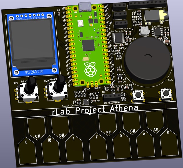
Derived from the previous 555 Synth Punk build project
The design is built of modules which can be independently sourced, designed and prototyped before integration into a complete design.
The following modules are proposed to be in the design, being available and at reasonable cost:
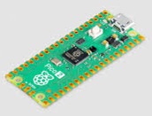
The Raspberry Pi Pico module is based on the RP2040 microprocessor. The module includes flash memory, power supply, crystal clock and a USB interface. It is an easy way to to integrate this processor without detail PCB layout and at attractive cost. The Pi Pico Module have different variants which are pin compatible. They offer different USB Connectors(Micro-B, USB-C), Wireless and bluetooth integrated, and a higher performance version in the RP2350. Pi Pico Data sheet
The RP2040 is an ARM Cortex M0+ 32 bit processor which operates at 133MHz and includes a wide range of integrated peripherals. RP2040 Data sheet
High quality software support for the RP2040 and Pi Pico Modules is available in C/C++ (C SDK, and Arduino Pi Pico), and Python(Micropython, and CircuitPython)
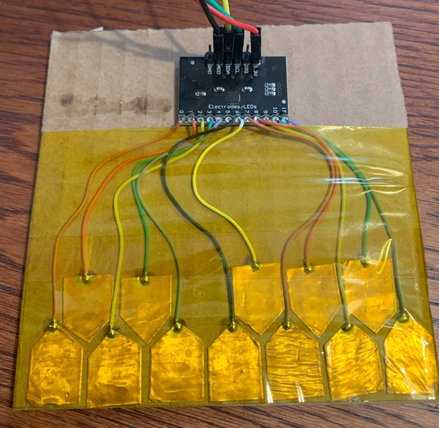 A number of different keyboard switch types were considered including push butttons, stylophone type stylus and capacitive touch. The later was chosen for simplicity and the capability to play chords with multiple notes simultaneously.
A few different alternatives for the capacitive touch keyboard layout and interface were tested. The keyboard was prototyped with copper tape covered in kapton tape to simulate the PCB pads and solder mask in the final PCB. The Pi Pico does support direct connection of GPIO pins to interface capacitive touch switches using the CircuitPython touchio library, However it uses a lot of GPIO pins for a 12 key keyboard. It was decided to us a specialised Capacitive touch chip with and I2C interface MPR121. This chip is very small and will present a good challenge in construction, however it is available already mounted on low cost modules for prototyping. The chip supports up to 4 different I2C addresses allowing additional octave to be added.
The Pi Pico supports PWM output to a GPIO pin for audio tone output. The resulting output is rather noisy as described in section 3.4.1 of the RP2040 hardware interface manual. It was choseb to implement the low noise 3.3V audio supply, the buffer, and the filter circuit.
In addition to the PWM a I2S audio DAC is included for higher quality stereo output. The PCM5102 DAC analog part is also powered from the low noise 3.3V supply
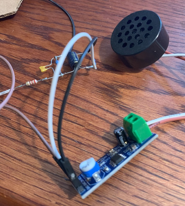
Low cost audio power amplifiers with 1W output power baaed on the LM386 are available. LM386 module
The LM386 IC can operate with few external components with a gain of 20 which is suitable for our application.LM386 Data sheet
The loudspeaker is proposed to be board mounted.30mm Loudspeaker
Audio Output to an external amplifier is provided via a 3.5mm stereo jack.
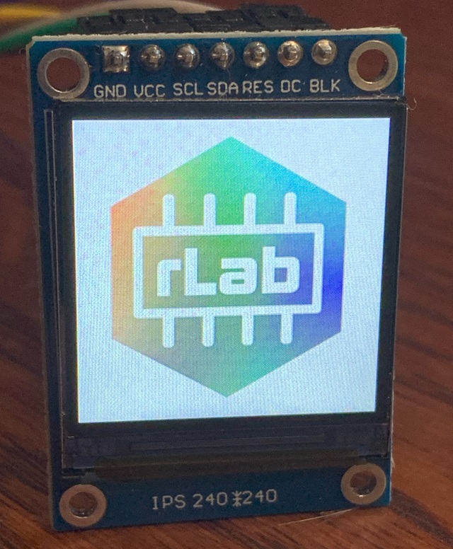
A colour LCD display was chosen for the device. Limited space allows for a 240 by 240 pixel 1.3 inch IPS display. The module is based on the ST7789 display IC and is supported by both Micropython and CircuitPython grahics libraries.
To interact with the device and display, two potentiometers and two push buttons are included.
The board provides spare GPIO connections and power supplies on 2.54mm female headers for external experimental devices. The I2c Bus is also brought out to a connector to daisy chain octaves or add other I2C devices.
Derived from Kicad BOM. All including VAT and shipping.
| Qty | Value | Footprint | References |
|---|---|---|---|
| 12 | 100n | Capacitor_SMD:C_0603_1608Metric | C3, C4, C6, C9, C10, C12, C13, C14, C15, C18, C22, C26 |
| 7 | 2u2 | Capacitor_SMD:C_0603_1608Metric | C7, C8, C16, C17, C19, C20, C27 |
| 7 | Conn_01x01_Pin | rLab_Keyboard:White_Key | J1, J2, J3, J4, J5, J6, J7 |
| 5 | Conn_01x01_Pin | rLab_Keyboard:Black_key_fill | J9, J10, J11, J12, J13 |
| 3 | 100R | Resistor_SMD:R_0603_1608Metric | R7, R8, R9 |
| 3 | 1u | Capacitor_SMD:C_0603_1608Metric | C1, C2, C5 |
| 3 | D | Diode_SMD:D_SOD-323 | D1, D2, D3 |
| 3 | NF | Resistor_SMD:R_0603_1608Metric | R1, R2, R3 |
| 2 | 1k | Resistor_SMD:R_0603_1608Metric | R10, R11 |
| 2 | 2n2 | Capacitor_SMD:C_0603_1608Metric | C24, C25 |
| 2 | 470R | Resistor_SMD:R_0603_1608Metric | R12, R13 |
| 2 | R_Network04 | Resistor_SMD:R_Array_Concave_4x0402 | RN1, RN2 |
| 1 | 0R | Resistor_SMD:R_0603_1608Metric | R4 |
| 1 | 10R | Resistor_SMD:R_0603_1608Metric | R14 |
| 1 | 220R | Resistor_SMD:R_0603_1608Metric | R6 |
| 1 | 220u | Capacitor_SMD:C_1206_3216Metric | C23 |
| 1 | 47n | Capacitor_SMD:C_0603_1608Metric | C21 |
| 1 | 47u | Capacitor_SMD:C_0805_2012Metric | C11 |
| 1 | 74LVC1G17 | Package_TO_SOT_SMD:SOT-353_SC-70-5 | U3 |
| 1 | 75k | Resistor_SMD:R_0603_1608Metric | R5 |
| 1 | AudioJack3_Switch | rLab_Keyboard:Jack_3.5mm_PJ342_Horizontal | J18 |
| 1 | Conn_01x04 | Connector_PinSocket_2.54mm:PinSocket_1x04_P2.54mm_Horizontal | J20 |
| 1 | Conn_01x04 | Connector_PinHeader_2.54mm:PinHeader_1x04_P2.54mm_Horizontal | J21 |
| 1 | Conn_01x04 | Connector_PinSocket_2.54mm:PinSocket_1x04_P2.54mm_Vertical | J19 |
| 1 | Conn_01x05 | Connector_FFC-FPC:TE_0-1734839-5_1x05-1MP_P0.5mm_Horizontal | J8 |
| 1 | Conn_01x07 | rLab_Keyboard:240LCD | J14 |
| 1 | Conn_01x13 | Connector_PinHeader_2.54mm:PinHeader_1x11_P2.54mm_Horizontal | J15 |
| 1 | Conn_01x13 | Connector_PinSocket_2.54mm:PinSocket_1x11_P2.54mm_Horizontal | J16 |
| 1 | Conn_01x13 | Connector_PinSocket_2.54mm:PinSocket_1x11_P2.54mm_Vertical | J17 |
| 1 | LM386 | Package_SO:SOIC-8_3.9x4.9mm_P1.27mm | U5 |
| 1 | LP5907MFX-3.3 | Package_TO_SOT_SMD:SOT-23-5 | U1 |
| 1 | Logo_Open_Hardware_Small | Symbol:OSHW-Logo_11.4x12mm_SilkScreen | SYM1 |
| 1 | MPR121QR2 | rLab_Keyboard:UQFN-20_3x3mm_P0.4mm | U2 |
| 1 | PCM5102 | Package_SO:TSSOP-20_4.4x6.5mm_P0.65mm | U4 |
| 1 | RaspberryPi_Pico | rLab_Keyboard:RPi_Pico_SMD_TH | A1 |
| 1 | RotaryEncoder_Switch_MP | rLab_Keyboard:RotaryEncoder_Alps_EC11E-Switch_Vertical_H20mm | SW1 |
| 1 | SW_MEC_5G | Button_Switch_THT:SW_PUSH_6mm_H5mm | SW2 |
| 1 | Speaker | rLab_Keyboard:30mm_Speaker | LS1 |
| 1 | ~ | rLab_Keyboard:Thumb_stick | ThumbStick1 |
emtee40/project-athena
A simple project to build and learn electronics and embedded design

M0LTE/pi-transceiver
An attempt to build a complete ham radio transceiver around a Raspberry Pi

lucococo/LucaudioESP32
ESP32 based board running SqueezeliteESP32 for audio streaming

wemaxon/esp32-audio-streamer
Hardware design for a WiFi/Bluetooth audio streamer using the esp32 microcontroller and the PCM5102A DAC, intended to be used with squeezelite firmware.


RADARC/Scout-Radio
Si4732 and Raspberry Pi Pico Radio device for Scouts to build and use to gain badges

iMike78/nest-mini-drop-in-pcb
Drop-in PCB replacement for the Google Nest Mini v2 with ESP32-S3, ESP32-P4 and optional ESP32-C6. Inspired by Onju Voice and Home Assistant Voice PE.


seb-ma/eInkFrame
A step by step guide to create a weather station (and more) in e-ink frame running with MagicMirror².
It measures 100 × 100 mm and has 2 copper layers, 1.6 mm thick.
78 parts, built around the 74LVC1G17Z, LM386, MPR121QR2 and LP5907MFX-3.3. The full list of its parts is on this page, with links to each part's symbol and footprint where PCBKit's library has them.
From the emtee40/project-athena repository on GitHub, at the commit this page was made from: the board is Kicad/RLab Keyboard/RLab Keyboard.kicad_pcb and its schematic Kicad/RLab Keyboard/KiCad-RP-Pico/Test/Test.kicad_sch. PCBKit opens the board in the browser, with nothing to install.
Its repository states no licence, so its author keeps all rights: ask emtee40 before reusing the design.