4 layers88 × 54 mm
Defcon badge
LastZactionHero/defcon-silent-disco
RP2040-based DEF CON silent disco badge — KiCad project + tooling
82 parts

 RADARC/Scout-Radio6
Si4732 and Raspberry Pi Pico Radio device for Scouts to build and use to gain badges
ScoutAM is an open-source printed circuit board by RADARC, from the RADARC/Scout-Radio repository on GitHub, published under the GPL-3.0 licence. It is a 2-layer board of 55 × 100 mm with 92 parts on 83 nets, routed with 812 tracks and 99 vias.
It is built around the 74LVC1G17Z, SI4732-A10-GS and TDA1308A, with the LP5907MFX-3.3, TP4056 and BAV99 among its other parts. Its parts include 30 capacitors, 24 resistors, 9 switches, 8 ICs and 5 diodes. It belongs with the radio and wireless and lEDs and displays boards and the RP2040 boards of this library.


Si4732 and Raspberry Pi Pico Radio device for Scouts to build and use to gain badges
Reading and District Amateur Radio Club works withl local Scouts groups and help them in support of their badges and activities
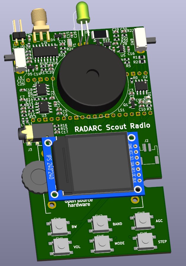
Derived from the RLab Reading Hackspace Project Athena
The following elements are in the prototype design, being commonly available at reasonable cost. Some of these may not be in the final design or optional modules to save cost:
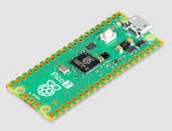
The Raspberry Pi Pico module is based on the RP2040 microprocessor. The module includes flash memory, power supply, crystal clock and a USB interface. It is an easy way to to integrate this processor without detail PCB layout and at attractive cost. The Pi Pico Module have different variants which are pin compatible. They offer different USB Connectors(Micro-B, USB-C), Wireless and bluetooth integrated, and a higher performance version in the RP2350. Pi Pico Data sheet
The RP2040 is an ARM Cortex M0+ 32 bit processor which operates at 133MHz and includes a wide range of integrated peripherals. RP2040 Data sheet
High quality software support for the RP2040 and Pi Pico Modules is available in C/C++ (C SDK, and Arduino Pi Pico), and Python(Micropython, and CircuitPython)
The Si4732 is an integrated AM/FM radio device which is digitally programmable over I2C. It covers a range of frequencies:
A side operated rotary encoder is installed on the prototype, but we might look at lower cost alternatives. There are 6 tactile push button switches which can be used to invoke the various radio functions. These controls can also be used to play simple nintendo like games on the radio.
The stereo audio audio output from the radio chip is amplified to provide an output to headphones of external speakers. This is then further amplified to drive an on board loudspeaker. The output from the radio chip is also fed to the ADC inputs on the Pi Pico to enable the Pi Pico to provide USB or Bluetooth feed to an external program such as WSJT-X. The Pi Pico may be able to decode locally digital protocols such as FT8 and display locally. The Pi Pico also provides a PWM audio output for beeps, morse code, and music for simple games.
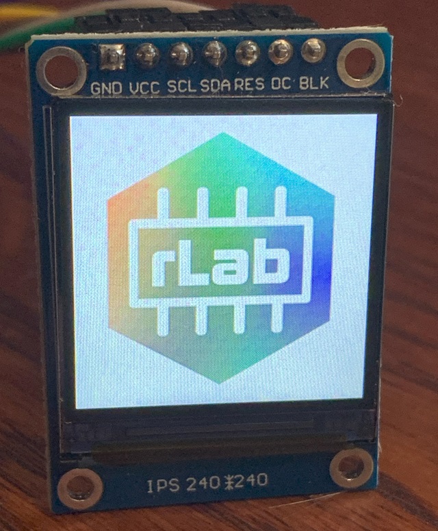
A colour LCD display was chosen for the device. Limited space allows for a 240 by 240 pixel 1.3 inch IPS display. The module is based on the ST7789 display IC and is supported by both Micropython and CircuitPython grahics libraries.
A high intensity white LED is provided under processor control to be used as a torch or for visual signalling.
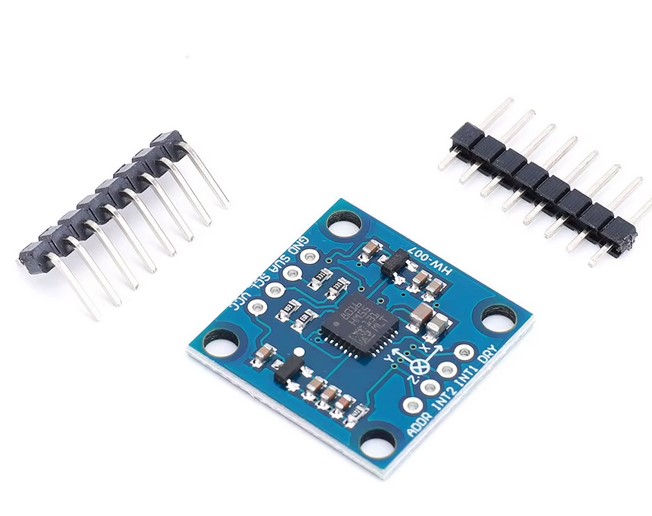
An optional compass module based on the LSM303 magnetometer, Compass and accelerometer device can be fitted.
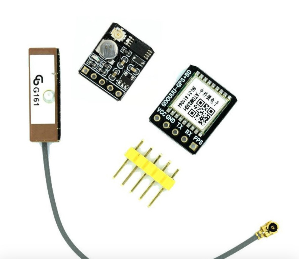
An optional GPS module based on the ATGM336H GPS receiver can be fitted
The following costs are based on the JLCPCB prototype build of five units. All costs are in UK pounds and include shipping and taxes
| Item | Cost £ |
|---|---|
| Placed components | 8.68 |
| Unplaced components | 8.44 |
| -------- | |
| Total £ | 17.12 |
The above component cost includes PCB, SMT components, Pi Pico, display and all switches and connectors. I does not include a case. The placed components were placed by JLCPCB. This cost is dominated by the radio chip and rotary encoder, better sourcing could easily get the component cost under £15.
| Item | Cost £ |
|---|---|
| LiPo Battery | 2.1 |
| SMA antenna | 2.59 |
| Compass module | 2.75 |
| GPS Module | 2.92 |
The build costs are again based on the five off prototype, so maybe not very representative of a larger batch. I excluded from the build the through hole components to save cost, also a couple of components that they did not have in stock. Build costs are driven by a mix of fixed costs per order, setup, solder stencil, etc. Also Costs per board and joint.There are then costs related to what components are used. Common components are already mounted on the pick and place machine and have low cost per component ( fraction of cent). Less common components are often low cost, but we pay $3 per component type to load the component spool to the pick and place, this cost often dominates the assembly costs. Assembly of through hole components and components and edge mounted components is possible but would attract increased cost.
For the five prototypes:
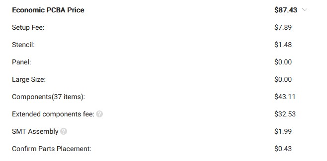
The placed component costs can be excluded, so $44.32 for five. With tax and shipping this is £11.08 per board. Rather expensive at prototype level, but for for a decent board volume (25) when I run through the pricing calculator I get £2.20 per board.
reinstallsys.sh
installs a system from scratch including Circuit Python. Runs on linux only atm.
Tasks are either small, medium or large (S/M/L)
In priority order:
| Qty | Value | Footprint | References |
|---|---|---|---|
| 12 | 100n | Capacitor_SMD:C_0603_1608Metric | C1, C2, C4, C5, C8, C9, C14, C17, C18, C22, C28, C29 |
| 8 | 10k | Resistor_SMD:R_0603_1608Metric | R6, R7, R9, R10, R13, R14, R23, R24 |
| 6 | B3FS | Scout:SW_Push_1P1T_NO_6x6mm_H9.5mm | SW1, SW2, SW3, SW4, SW5, SW6 |
| 5 | 1u | Capacitor_SMD:C_0603_1608Metric | C3, C7, C10, C16, C19 |
| 4 | 10u | Capacitor_SMD:C_0603_1608Metric | C11, C12, C26, C30 |
| 2 | 1 | Resistor_SMD:R_0805_2012Metric | R1, R2 |
| 2 | 220k | Resistor_SMD:R_0603_1608Metric | R4, R5 |
| 2 | 22p | Capacitor_SMD:C_0603_1608Metric | C13, C15 |
| 2 | 2k2 | Resistor_SMD:R_0603_1608Metric | R17, R18 |
| 2 | 2u2 | Capacitor_SMD:C_0603_1608Metric | C6, C23 |
| 2 | 4k7 | Resistor_SMD:R_0603_1608Metric | R11, R12 |
| 2 | 4u7 | Capacitor_SMD:C_0603_1608Metric | C20, C21 |
| 2 | 68k | Resistor_SMD:R_0603_1608Metric | R16, R22 |
| 2 | BAV99 | Package_TO_SOT_SMD:SOT-23 | D4, D5 |
| 2 | Ferrite Bead | Inductor_SMD:L_0603_1608Metric | L1, L2 |
| 2 | SW_SPDT | Button_Switch_THT:SW_Slide_SPDT_Angled_CK_OS102011MA1Q | SW8, SW9 |
| 1 | 100 | Resistor_SMD:R_0603_1608Metric | R21 |
| 1 | 100 | Resistor_SMD:R_2512_6332Metric | R19 |
| 1 | 180nH | Inductor_SMD:L_0603_1608Metric | L3 |
| 1 | 18p | Capacitor_SMD:C_0603_1608Metric | C24 |
| 1 | 1k | Resistor_SMD:R_0603_1608Metric | R8 |
| 1 | 21k | Resistor_SMD:R_0603_1608Metric | R15 |
| 1 | 220 | Resistor_SMD:R_0603_1608Metric | R20 |
| 1 | 220uH | Inductor_SMD:L_0603_1608Metric | L5 |
| 1 | 2N7002 | Package_TO_SOT_SMD:SOT-23 | Q2 |
| 1 | 300 | Resistor_SMD:R_0603_1608Metric | R3 |
| 1 | 32.768KHz 3215 | Crystal:Crystal_SMD_3215-2Pin_3.2x1.5mm | Y1 |
| 1 | 33p | Capacitor_SMD:C_0603_1608Metric | C27 |
| 1 | 4.7uH | Inductor_SMD:L_0603_1608Metric | L4 |
| 1 | 470n | Capacitor_SMD:C_0603_1608Metric | C25 |
| 1 | 74LVC1G17 | Package_TO_SOT_SMD:SOT-23-5 | U8 |
| 1 | AO3401A | Package_TO_SOT_SMD:SOT-23 | Q1 |
| 1 | ATGM336 | Scout:ATGM336 | U1 |
| 1 | Conn_01x02 | Connector_PinHeader_2.54mm:PinHeader_1x02_P2.54mm_Horizontal | J5 |
| 1 | Conn_01x02 | Connector_JST:JST_PH_S2B-PH-SM4-TB_1x02-1MP_P2.00mm_Horizontal | J2 |
| 1 | Conn_01x07 | Scout:240LCD | J1 |
| 1 | Conn_Coaxial | Connector_Coaxial:SMA_Samtec_SMA-J-P-H-ST-EM1_EdgeMount | J4 |
| 1 | LED | LED_THT:LED_D5.0mm_Horizontal_O6.35mm_Z9.0mm | D3 |
| 1 | LED_Orange | LED_SMD:LED_0603_1608Metric | D2 |
| 1 | LED_Red | LED_SMD:LED_0603_1608Metric | D1 |
| 1 | LISM303 | Scout:LISM303 | U4 |
| 1 | LP5907MFX-3.3 | Package_TO_SOT_SMD:SOT-23-5 | U5 |
| 1 | Logo_Open_Hardware_Small | Symbol:OSHW-Logo_11.4x12mm_SilkScreen | SYM1 |
| 1 | MD8002 | Package_SO:SO-8_3.9x4.9mm_P1.27mm | U7 |
| 1 | PJ-342 | Scout:Jack_3.5mm_PJ342_Horizontal | J3 |
| 1 | RaspberryPi_Pico | Scout:RPi_Pico_SMD_TH | A1 |
| 1 | SIQ-02FVS3 | Scout:SIQ-02FVS3_Rotary_Encoder | SW7 |
| 1 | Si4732-A10 | Package_SO:SOIC-16_4.55x10.3mm_P1.27mm | U6 |
| 1 | Speaker | Scout:30mm_Speaker | LS1 |
| 1 | TDA1308 | Package_SO:SO-8_3.9x4.9mm_P1.27mm | U3 |
| 1 | TP4056 | Package_SO:SOIC-8-1EP_3.9x4.9mm_P1.27mm_EP2.29x3mm | U2 |
LastZactionHero/defcon-silent-disco
RP2040-based DEF CON silent disco badge — KiCad project + tooling

cfbird/usb3-sdr
USB3 direct-sampling HF SDR: AD9649 ADC -> ECP5 FPGA DDC -> FT601 USB 3. KiCad 9 + Verilog, co-designed by Claude and Gemini (AGY).


abzman/arduino-controlled-tv-tuner
controlling a salvaged fm1236 tv tuner

Fihdi/ATS-20-Eurorack
A clone of the ATS 20 from PU2CLR in Eurorack Format (3U height). The circuit contains jumpers to switch between standalone mode and Eurorack.


KOEGlike/meko
A linux music player with ddr3, a 70hz e-paper display and a haptic touchpad

kholia/ConsensusBasedTimeSync
A portable, efficient, passive, consensus based (relative) time synchronization mechanism over radio waves. Cost-effective radio receivers too!
It measures 55 × 100 mm and has 2 copper layers, 1.6 mm thick.
92 parts, built around the 74LVC1G17Z, SI4732-A10-GS, TDA1308A and LP5907MFX-3.3. The full list of its parts is on this page, with links to each part's symbol and footprint where PCBKit's library has them.
From the RADARC/Scout-Radio repository on GitHub, at the commit this page was made from: the board is Kicad/Scout_radio/ScoutAM.kicad_pcb and its schematic Kicad/Scout_radio/KiCad-RP-Pico/Test/Test.kicad_sch. PCBKit opens the board in the browser, with nothing to install.
Its repository publishes it under the GPL-3.0 licence: you may reuse it on that licence's terms (keep the author's notice, and for a copyleft licence share your changes alike).