2 layers55 × 100 mm
ScoutAM
RADARC/Scout-Radio
Si4732 and Raspberry Pi Pico Radio device for Scouts to build and use to gain badges
92 parts6GPL-3.0

 Fihdi/ATS-20-Eurorack2
A clone of the ATS 20 from PU2CLR in Eurorack Format (3U height). The circuit contains jumpers to switch between standalone mode and Eurorack.
ATS-20 is an open-source printed circuit board by Fihdi, from the Fihdi/ATS-20-Eurorack repository on GitHub. It is a 2-layer board of 122.1 × 128.5 mm with 81 parts on 74 nets, routed with 538 tracks and 77 vias.
It is built around the LM386, TDA1308A and TL072, with the L7805 and BC847 among its other parts. Its parts include 17 capacitors, 15 resistors, 11 connectors, 8 switches and 5 ICs. It belongs with the audio and music and radio and wireless boards and the AVR (ATmega, ATtiny) boards of this library.


An ATS-20 Radio port in 3U height. Jumpers on the PCB lets the device be used as an Eurorack module or as a standalone all-band receiver.
A regular 12VDC wall wart or a 9V battery can be used for standalone usage.
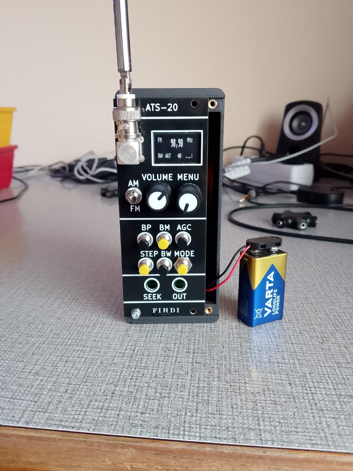
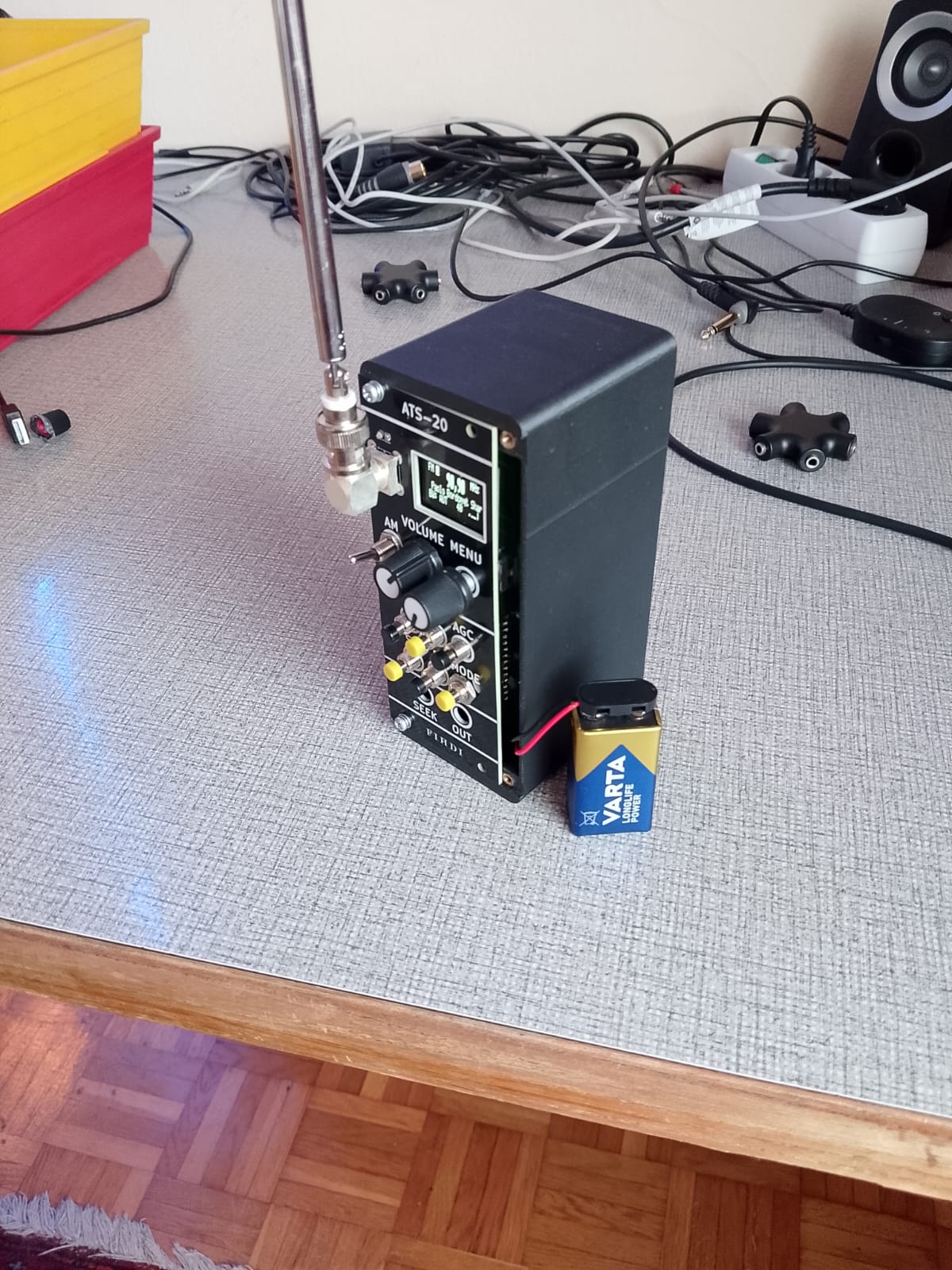
Changing the jumper on the back of the module from SA (Stand Alone mode) to ER (Eurorack mode) changes the output from headphone level to Eurorack level. In stand alone mode, the radio output is routed to an LM386 class AB amplifier. An 8-Ohm speaker can be connected to the amplifier with the SP+ and SP- screw terminals.
The I2C ADDR jumpers change the I2C address of the SI4732 IC.
The 3D model for the case was designed by SapuSeven. The model in this github project is designed for the AS03208AS-HT speaker by PUI audio. The .step model can be downloaded modified to fit different speakers.
The module that you see in the picture above is using circuit boards that were fabricated by PCBWay They have excellent build quality and I can recommend using their service to build your own projects! I used the "Black" option for the soldermask and the surface has very deep and glossy black finish, which looks amazing, they also have an option for a "Matte Black" finish which I will try next time. Thank you PCBWay for sponsoring this module. This is the first project that features a small OLED display, and thus the first project where I cut out a square section from the frontplate. This worked out really well and the corners are clean 90 degrees with no rounding. They are also having a 3D printing service, which means you can order the boards and the case for this radio all in one place.
| Qty | Value | Footprint | References |
|---|---|---|---|
| 13 | , , , , , , , , , , , , | ||
| 6 | 1u | Capacitor_SMD:C_0805_2012Metric | C1, C11, C12, C14, C101, C103 |
| 6 | 4k7 | Resistor_SMD:R_0805_2012Metric | R7, R8, R9, R10, R101, R102 |
| 6 | SW_Push | Library:PushButton | SW1, SW2, SW3, SW4, SW5, SW6 |
| 4 | 100k | Resistor_SMD:R_0805_2012Metric | R1, R4, R11, R12 |
| 4 | 1N4148 | Diode_SMD:D_SOD-323_HandSoldering | D1, D2, D14, D15 |
| 4 | Conn_01x02_Pin | Connector_PinHeader_2.54mm:PinHeader_1x03_P2.54mm_Vertical | J9, J10, J13, J15 |
| 3 | 47k | Resistor_SMD:R_0805_2012Metric | R2, R6, R13 |
| 2 | 100n | Capacitor_SMD:C_0805_2012Metric | C4, C102 |
| 2 | 100u | Capacitor_SMD:C_Elec_6.3x7.7 | C2, C13 |
| 2 | 10u | Capacitor_SMD:C_0805_2012Metric | C3, C6 |
| 2 | 22pF | Capacitor_SMD:C_0805_2012Metric | C9, C10 |
| 1 | 100k | Potentiometer_THT:Potentiometer_Alpha_RD902F-40-00D_Dual_Vertical | RV2 |
| 1 | 10k | Resistor_SMD:R_0805_2012Metric | R3 |
| 1 | 1k | Resistor_SMD:R_0805_2012Metric | R5 |
| 1 | 1nF | Capacitor_SMD:C_0805_2012Metric | C7 |
| 1 | 32.768k | Crystal:Crystal_SMD_3225-4Pin_3.2x2.5mm | Y2 |
| 1 | 470nF | Capacitor_SMD:C_0805_2012Metric | C8 |
| 1 | 470u | Capacitor_SMD:C_Elec_6.3x7.7 | C5 |
| 1 | Arduino_Nano_Every | Module:Arduino_Nano | A1 |
| 1 | AudioJack2 | Library:MonoTRS | J17 |
| 1 | AudioJack3 | Library:StereoTRS | J2 |
| 1 | BC847 | Package_TO_SOT_SMD:SOT-23 | Q1 |
| 1 | Conn_01x04_Pin | Connector_PinSocket_2.54mm:PinSocket_1x04_P2.54mm_Vertical | J7 |
| 1 | Conn_02x05_Odd_Even | Connector_IDC:IDC-Header_2x05_P2.54mm_Vertical | J1 |
| 1 | Conn_Coaxial | Library:BNC5-J-P-GN-ST-TH2D | J4 |
| 1 | L7805 | Package_TO_SOT_SMD:SOT-223-3_TabPin2 | U6 |
| 1 | LM386 | Package_SO:SOIC-8_3.9x4.9mm_P1.27mm | U2 |
| 1 | RotaryEncoder_Switch | Rotary_Encoder:RotaryEncoder_Alps_EC11E-Switch_Vertical_H20mm | SW8 |
| 1 | SI4732 | Package_SO:SOIC-16_4.55x10.3mm_P1.27mm | U9 |
| 1 | SW_SPDT | Library:Switch | SW7 |
| 1 | Screw_Terminal_01x02 | TerminalBlock_RND:TerminalBlock_RND_205-00287_1x02_P5.08mm_Horizontal | J103 |
| 1 | Screw_Terminal_01x02 | TerminalBlock_Phoenix:TerminalBlock_Phoenix_MKDS-1,5-2-5.08_1x02_P5.08mm_Horizontal | J6 |
| 1 | TDA1308 | Package_SO:SOIC-8_3.9x4.9mm_P1.27mm | U5 |
| 1 | TL072 | Package_SO:SOIC-8_3.9x4.9mm_P1.27mm | U1 |
The 77 most common of 81 parts.
RADARC/Scout-Radio
Si4732 and Raspberry Pi Pico Radio device for Scouts to build and use to gain badges

abzman/arduino-controlled-tv-tuner
controlling a salvaged fm1236 tv tuner

LastZactionHero/defcon-silent-disco
RP2040-based DEF CON silent disco badge — KiCad project + tooling


dreamster/dreamster-board
Specialized Arduino board which is the heart of the Dreamster Robot.

eljotx/SDR-TRX-on-ESP32-A1S
This repository describes an SDR transceiver based on the ESP32 A1S processor, using an ILI9341 color touchscreen display, and a Si5351 oscillator.

ryomuk/tangnano20k-vectrex
Tang Nano 20K top level module for Dar's Vectrex

SamyIOoOI/RetroCom
A 4-Station one-to-one two-way INTERCOM built around the AT89C52-PI24 RetroMCU (8051 Core).
It measures 122.1 × 128.5 mm and has 2 copper layers, 1.6 mm thick.
81 parts, built around the LM386, TDA1308A, TL072 and L7805. The full list of its parts is on this page, with links to each part's symbol and footprint where PCBKit's library has them.
From the Fihdi/ATS-20-Eurorack repository on GitHub, at the commit this page was made from: the board is ATS-20.kicad_pcb and its schematic ATS-20.kicad_sch. PCBKit opens the board in the browser, with nothing to install.
Its repository states no licence, so its author keeps all rights: ask Fihdi before reusing the design.