6 layers172 × 100 mm

 electricui/electricui-arena27
Hardware for continuous integration testing of serial interfaces and microcontrollers
Electricui arena is an open-source printed circuit board by electricui, from the electricui/electricui-arena repository on GitHub, published under the MIT licence. It is a 4-layer board of 220 × 120 mm with 268 parts on 446 nets, routed with 2,024 tracks and 358 vias.
It is built around the AP2553AW6, SN74LV4051APW and AP2112K-3.3, with the MAX4999ETJ, SN74LVC1G66DCK and USBLC6-4 among its other parts. Its parts include 85 capacitors, 73 resistors, 39 ICs, 20 diodes and 18 connectors. It belongs with the interfaces and adapters boards of this library.


Hardware for continuous integration testing of serial interfaces and microcontrollers. Background and more detailed discussion outlined in this blog post.
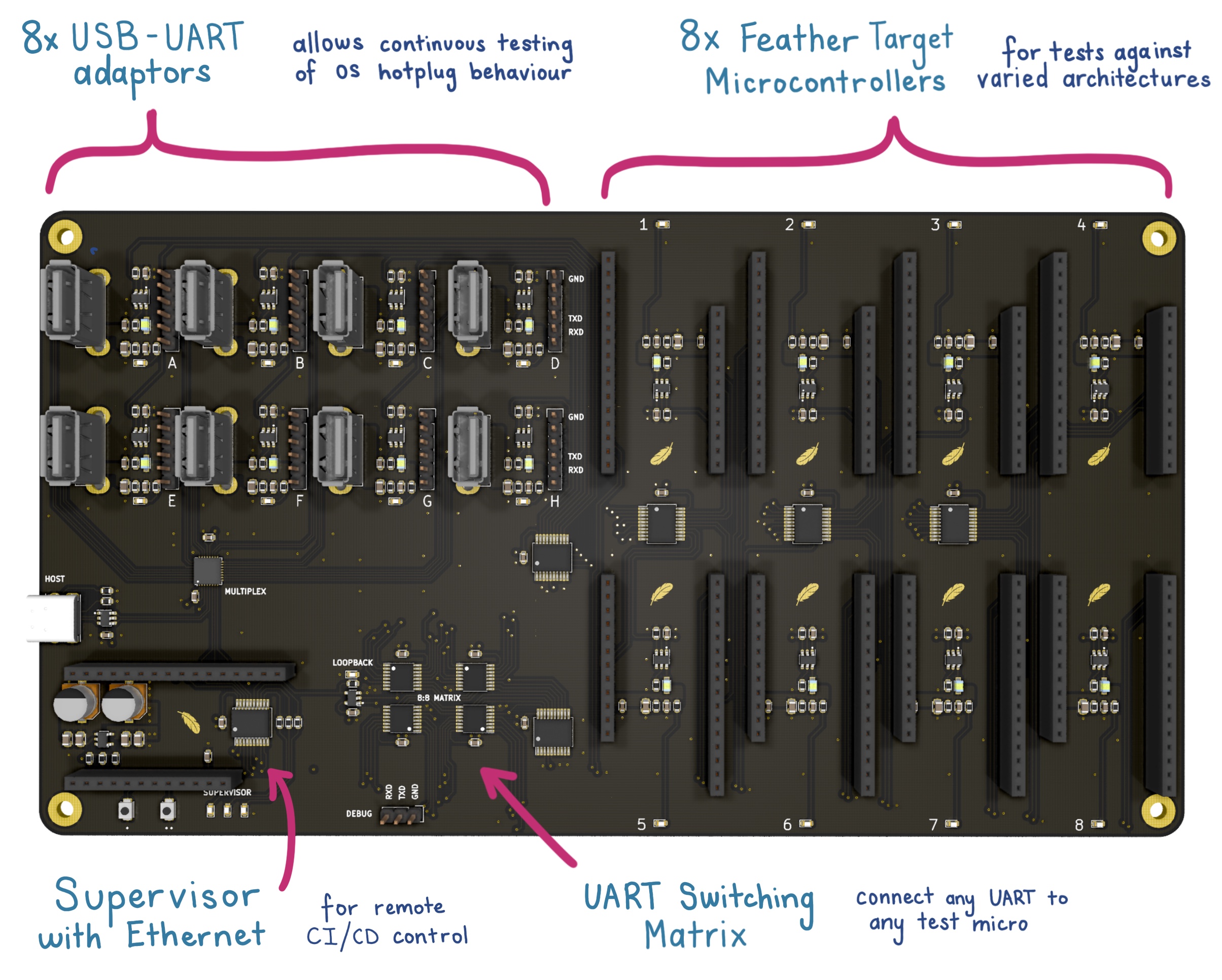
The board (KiCAD files in /hardware) exposes control to a CI build worker to power up any of the USB-UART adaptors in either loopback mode, or connected to any one of the hardware targets for a total test matrix of 72 combinations.
Intended to run tests for hot-plug detection (by controlling the mux or USB power control), disconnection handling (by re-routing serial to the void) and to validate a wide range of microcontroller architectures and their corresponding toolchains.
Up to 8 USB ports are provided behind a USB mux from the host.
Individual power switching is available per-port, with optional routing of the USB-UART adaptor's serial lines to either loop-back, or to one of the target microcontrollers.
The following adaptors are used as test adaptors:
In the future, we hope to add Bluetooth/WiFi adaptors for wireless tests against compatible targets.
8 power-switched targets are supported with connections to hardware serial. The Adafruit Feather specification is used, as a majority of planned targets are available in Feather format.
The following boards are used as test devices:
Test hardware will be flashed with a mix of native 'bare metal' images, and at least one target will act as validation of the Arduino framework.
When populating the test Feather boards with headers, use 'stacking' headers to allow for future sensor/display additions to targets.
An additional Feather is provided to act as the supervisor. This connects to the CI server using a ethernet featherwing.
The supervisor (through I2C expanders) controls power switches to each of the serial adaptors and test devices, and has 2 IO lines to each microcontroller to allow for input/output checks.
An analog line is shared across all modules, with the intent of using the supervisor's DAC output, allowing additional tests.
Firmware is in /firmware
See /hardware/output/arena-BOM.html for PCB BOM.
| Qty | Value | Footprint | References |
|---|---|---|---|
| 31 | 100n_X7R_1608M | Applidyne_Capacitor:CAPC1608X90N | C1, C3, C10, C11, C12, C13, C14, C15, C17, C19, C21, C23, C25, C27, C29, C31 +15 |
| 20 | 1K00_1608M | Applidyne_Resistor:RESC1608X50N | R1, R2, R3, R4, R10, R12, R14, R16, R18, R20, R28, R30, R32, R34, R36, R38 +4 |
| 20 | 4u7_X7R_2012M | Applidyne_Capacitor:CAPC2012X110N | C2, C16, C18, C20, C22, C24, C26, C28, C30, C32, C34, C36, C38, C40, C42, C44 +4 |
| 18 | LED_YELLOW_1608M | Applidyne_LED:LEDC1608X80L40N | D1, D2, D3, D4, D5, D6, D10, D12, D13, D14, D15, D16, D17, D18, D19, D20 +2 |
| 17 | 10K0_1608M | Applidyne_Resistor:RESC1608X50N | R23, R57, R61, R63, R65, R67, R69, R71, R73, R75, R77, R79, R81, R83, R85, R87 +1 |
| 16 | 10R_1608M | Applidyne_Resistor:RESC1608X50N | R60, R62, R64, R66, R68, R70, R72, R74, R76, R78, R80, R82, R84, R86, R88, R90 |
| 16 | 220R_2012M | Applidyne_Inductor:INDC2012X145N | FB1, FB2, FB3, FB4, FB5, FB6, FB7, FB8, FB9, FB10, FB11, FB12, FB13, FB14, FB15, FB16 |
| 16 | 470n_X7R_1608M | Applidyne_Capacitor:CAPC1608X90N | C64, C66, C68, C70, C72, C74, C76, C78, C80, C82, C84, C86, C88, C90, C92, C94 |
| 16 | 4n7_X7R_1608M | Applidyne_Capacitor:CAPC1608X90N | C65, C67, C69, C71, C73, C75, C77, C79, C81, C83, C85, C87, C89, C91, C93, C95 |
| 16 | AP2553A | Applidyne_SOT:SOT95P280X145-6L50N | U13, U15, U17, U19, U21, U23, U25, U27, U30, U31, U32, U33, U34, U35, U36, U37 |
| 9 | ADAFRUIT_FEATHER_BREAKOUT | Applidyne_Connector:ADAFRUIT_FEATHER | U14, U16, U18, U20, U22, U24, U26, U28, U29 |
| 9 | LOGO | Applidyne_Logo:FEATHER_LOGO4300X4300_MASK | G***, G***, G***, G***, G***, G***, G***, G***, G*** |
| 8 | 100K_1608M | Applidyne_Resistor:RESC1608X50N | R27, R29, R31, R33, R35, R37, R39, R41 |
| 8 | 43K_1608M | Applidyne_Resistor:RESC1608X50N | R5, R7, R9, R11, R13, R15, R17, R19 |
| 8 | CONN_01X06 | Applidyne_Connector_Wurth:61300611121 | P1, P2, P3, P4, P5, P6, P7, P8 |
| 8 | USB_A_FEMALE_VERTICAL | Applidyne_USB:TE_1734366-1 | J1, J2, J3, J4, J5, J6, J7, J8 |
| 6 | MCP23008-E_SS | Applidyne_SOP:SOP20P65_720X780X200L75X30N | U2, U3, U5, U6, U7, U8 |
| 4 | MNT_M3_PLATED | Applidyne_Mount:MTGP650H330 | MNT1, MNT2, MNT3, MNT4 |
| 4 | SN74LV4051APW | Applidyne_SOP:SOP16P65_500X640X120L62X24N | U9, U10, U11, U12 |
| 2 | 100u_ELEC_35V_660X580M | Applidyne_Capacitor:CAPAE660X580DD180L260N | C62, C63 |
| 2 | 4K7_1608M | Applidyne_Resistor:RESC1608X50N | R21, R22 |
| 2 | 5K76_1608M | Applidyne_Resistor:RESC1608X50N | R43, R44 |
| 2 | B3U-1000P_SPST-NO_SMD | Applidyne_Switch:B3U-1000P | SW1, SW2 |
| 1 | AP2112K-3.3 | Applidyne_SOT:SOT95P280X145-5L30N | U1 |
| 1 | CONN_01X03 | Applidyne_Connector_Wurth:61300311121 | P9 |
| 1 | LED_GREEN_1608M | Applidyne_LED:LEDC1608X80L40N | D11 |
| 1 | LED_RED_1608M | Applidyne_LED:LEDC1608X80L40N | D9 |
| 1 | LOGO | Applidyne_Logo:SQUID_LOGO_4730X2500_silk | G*** |
| 1 | LOGO | Applidyne_Logo:EUI_LOGO_1000X940_MASK | G*** |
| 1 | MAX4999ETJ | Applidyne_QFN:QFN33P50_500X500X100L40X24T345N | U4 |
| 1 | SN74LVC1G66 | Applidyne_SOT:SOT95P240X110-5L16N | U39 |
| 1 | USBLC6 | Applidyne_SOT:SOT95P280X145-6L50N | U38 |
| 1 | USB_C_SOCKET_RA_PTH_SIMPLE | Applidyne_USB:USB_C_PTH_GCT_USB4085 | J9 |

inuyasha10121/RPi4CustomRemoteKVM
A custom remote KVM setup based around a Raspberry Pi 4.


Scottapotamas/spe-marine-node
Prototype project to build an underwater sensor node, powered by and communicating with the surface via Single Pair Ethernet (10BASE-T1L + 802.3cg)


conol-ai/openmicrokbd
Open-source recreation of OpenAI's Codex Micro macropad — PCB written in CoHDL, an AI-native hardware description language. Rust firmware (embassy) + companion app (makepad). MIT licensed. https://openmicrokbd.org

Jana-Marie/EF-S-Adapter
Hard- and Firmware to control different EF and EF-S lenses
It measures 220 × 120 mm and has 4 copper layers, 2 mm thick.
268 parts, built around the AP2553AW6, SN74LV4051APW, AP2112K-3.3 and MAX4999ETJ. The full list of its parts is on this page, with links to each part's symbol and footprint where PCBKit's library has them.
From the electricui/electricui-arena repository on GitHub, at the commit this page was made from: the board is hardware/hardware.kicad_pcb. PCBKit opens the board in the browser, with nothing to install.
Its repository publishes it under the MIT licence: you may reuse it on that licence's terms (keep the author's notice, and for a copyleft licence share your changes alike).