

2 layers160 × 238.5 mm
 EdSmithe/meniscus-controller
Closed-loop meniscus pressure controller for inkjet printing: custom KiCad PCB, Arduino control firmware, Python GUI
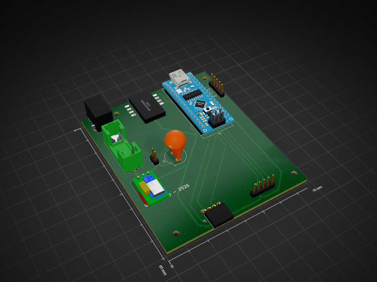
Meniscus controller is an open-source printed circuit board by EdSmithe, from the EdSmithe/meniscus-controller repository on GitHub. It is a 2-layer board of 76 × 91 mm with 10 parts on 36 nets, routed with 89 tracks and 1 via.
It is built around the MPXV5100DP and 0PTF0078P. Its parts include 5 connectors, 3 ICs and 1 capacitor. It belongs with the AVR (ATmega, ATtiny) boards of this library.
A closed-loop pressure controller that holds the ink meniscus in a drop-on-demand inkjet nozzle. It runs a peristaltic pump forwards or backwards to hold a pressure setpoint between about −35 mbar and +15 mbar. It's built around a custom two-layer PCB that I designed in KiCad. This was my first PCB, and I learned KiCad from scratch to make it.
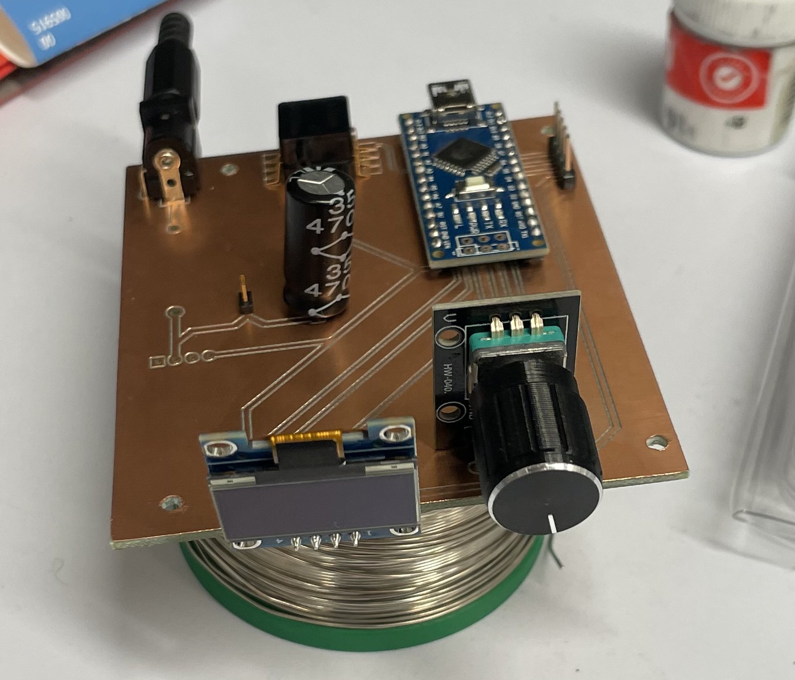 V1 board, milled in the department, during assembly. Including and OLED display and a rotary encoder.
| Purpose | Hold the meniscus pressure at a piezo inkjet nozzle, with additional controls needed for experimental printing: Fill (vacuum) and Purge (positive pressure) |
| Control | 100 Hz loop, a two-mode controller with separate gain sets for vacuum and positive pressure, and pulse-density control below the motor's stall threshold |
| Sensor | NXP MPXV5100DP differential pressure sensor, read ratiometrically by a 10-bit ADC |
| Actuator | Williamson 200 Series peristaltic pump (24 V DC), driven by an L298N H-bridge module |
| MCU | Arduino Nano (ATmega328P) |
| PCB | 2 layers, 76 × 91 mm, 1.6 mm FR-4, KiCad 9. V1 was milled in the department, V2 was made by PCBWay |
| Interfaces | OLED and rotary encoder on the unit; text commands over USB serial; Python/browser GUI with live plotting and CSV logging |
| Mechanical | SolidWorks mount that holds the whole pump assembly for lab use |
The printer deposits highly viscous inks, usually liquid crystals, through a piezo drop-on-demand nozzle. Inks like these leave very little margin on nozzle pressure. A few mbar too positive and ink weeps out of the nozzle; a few mbar too negative and air is drawn in and the nozzle de-primes. The working window is a slight vacuum that holds the meniscus flat, just inside the nozzle.
This controller holds that pressure in the ink reservoir and the line feeding the nozzle. Prints run for hours, and the pressure drifts as ink leaves the reservoir, so holding a level meniscus over a long print is the whole point of closing the loop rather than setting a head height and leaving it. Two manual functions cover the rest of the workflow: Fill draws ink through to prime the nozzle, and Purge pushes ink forwards to clear a bubble or a blockage.
hardware/bom.csv).flowchart LR
subgraph PCB["Controller PCB"]
FUSE["5×20 mm fuse"] --> R24(("24 V"))
R24 --- CB["470 µF bulk cap"]
R24 --> REG["OKI-78SR<br/>5 V switching regulator"]
REG --> R5(("5 V"))
R5 --> MCU["Arduino Nano"]
R5 --> SEN["MPXV5100DP<br/>pressure sensor"]
SEN -->|"VOUT → A0"| MCU
OLED["128×64 OLED"] <-->|"I²C"| MCU
ENC["Rotary encoder"] --> MCU
end
PSU["24 V DC supply"] --> FUSE
R24 --> DRV["L298N H-bridge<br/>(off-board)"]
MCU -->|"ENA (PWM), IN1, IN2"| DRV
DRV --> PUMP["Peristaltic pump"]
PUMP -->|"pressure line"| SEN
MCU <-->|"USB serial, 115200 baud"| PC["Python GUI"]| Stage | Date | What happened |
|---|---|---|
| Perfboard prototype | Autumn 2025 | Nano, sensor and L298N module hand-wired. Used to develop the firmware and the PC GUI |
| First schematic | Jan 2026 | Started with an L298 H-bridge IC on the board, then moved the driver off-board to keep motor switching currents away from the sensor |
| Power stage | Jan 2026 | Added a 24 V barrel jack, Murata CRE1S2405SC isolated converter, fuse holder, bulk capacitor, and sockets for the encoder and display. First routing pass |
| V1 PCB | Feb 2026 | Replaced the regulator with an OKI-78SR. Board milled and assembled in the department, then checked and validated |
| V2 PCB | Mar 2026 | Minor copper and silkscreen revisions after V1, then ordered from PCBWay |
| Pump mount | Jun 2026 | SolidWorks mount for the complete pump assembly |
My first choice for the 24 V → 5 V stage was a Murata CRE1S2405SC, a 1 W isolated DC-DC module. This type of converter only holds its output near 5 V when it carries a significant load. The controller (Nano, sensor, OLED and the L298N logic) draws very little, so the 5 V rail wasn't regulated properly. I also didn't need isolation, since everything shares one ground.
I replaced it with a Murata OKI-78SR, a non-isolated switching regulator. It has no minimum-load requirement and accepts 7–36 V in. The lesson was to check load regulation and minimum-load figures on the datasheet, not just the input and output voltages.
The full BoM is in hardware/bom.csv. It's split into parts soldered to the board and off-board modules and assemblies:
| Ref | Part | Role |
|---|---|---|
| A1 | Arduino Nano (ATmega328P) | Controller |
| IC1 | NXP MPXV5100DP | Differential pressure sensor |
| IC2 | Murata OKI-78SR-5/1.5-W36-C | 24 V → 5 V switching regulator |
| U2 + F1 | Littelfuse 0PTF0078P + 5×20 mm fuse | Input protection |
| C1 | 470 µF 35 V electrolytic | Bulk decoupling, 24 V rail |
| J1–J5 | Headers, sockets, DC jack | Encoder, display, power input, motor-driver control and power |
| – | L298N module, SSD1306 OLED, HW-040 encoder, Williamson 200 Series pump | Off-board |
Wiring and connector pinouts: docs/wiring.md.
firmware/meniscus_controller/ is an Arduino sketch for the Nano. The full explanation is in docs/control-system.md. In short:
Serial commands (115200 baud, newline-terminated):
| Command | Example | Effect |
|---|---|---|
SET <value> [unit] | SET -25 mbar, SET -0.36 psi | New setpoint (unit defaults to the display unit) |
GET | GET | Report the current setpoint |
HELP | HELP | List commands |
Telemetry. One CSV line at 20 Hz: setpoint_mbar,measured_mbar,pwm,pulse,vcc_mV,adc, for example -25,-24.812,0,1,5012,231. Everything else the controller sends is plain text, so the GUI can tell status messages and telemetry apart.
gui/ is a small Python app built with Eel that serves a browser UI. You can connect to the controller, send setpoints, watch a live pressure plot (Chart.js), read the device's terminal output and log telemetry to timestamped CSV files.
hardware/mechanical/solidworks/ holds the SolidWorks assembly (PumpAssem.SLDASM). It mounts the pump, pump head and controller board together for use in the lab. The pump-head models come from the manufacturer.
meniscus-controller/
├── firmware/meniscus_controller/   Arduino sketch
├── gui/                            Python + browser GUI (Eel)
├── hardware/
│   ├── pcb/                        KiCad 9 project + 3D STEP of the board
│   ├── gerbers/v1-prototype/       Fabrication files, department-milled board
│   ├── gerbers/v2-pcbway/          Fabrication files, PCBWay board
│   ├── mechanical/solidworks/      Pump mount assembly
│   └── bom.csv                     Bill of materials
└── docs/ Control write-up, wiring, imagesFirmware. In the Arduino IDE, install the Adafruit SSD1306 and Adafruit GFX libraries. Select Arduino Nano (ATmega328P), open firmware/meniscus_controller/meniscus_controller.ino and upload it.
GUI. You need Python 3.10 or newer.
cd gui
pip install -r requirements.txt
# set PumpPort in config.txt, e.g. 'COM9' on Windows or '/dev/tty.usbserial-XXXX' on macOS
python meniscus_gui.py        # opens http://localhost:8000
Hardware files. Open hardware/pcb/meniscus-controller.kicad_pro in KiCad 9. The schematic and board carry their own copies of every symbol and footprint, so they open without extra libraries. Third-party library files aren't included here.
Built for use in the lab at the University of Oxford, as part of my work on a piezo-driven inkjet printing system in the Oxford Fluid Dynamics Laboratory.
Edward Smith · MEng Engineering Science, University of Oxford · LinkedIn
| Qty | Value | Footprint | References |
|---|---|---|---|
| 1 | 0PTF0078P | Fuse1:0PTF0078P | U2 |
| 1 | 24v Motor | Connector_PinHeader_2.54mm:PinHeader_1x02_P2.54mm_Vertical | J5 |
| 1 | Arduino_Nano_Every | Module:Arduino_Nano | A1 |
| 1 | C_Polarized | Capacitor_THT:CP_Radial_Tantal_D10.5mm_P5.00mm | C1 |
| 1 | Display | Connector_PinSocket_2.54mm:PinSocket_1x04_P2.54mm_Horizontal | J2 |
| 1 | Encoder Socket | Library:EncoderConnector-Throughmount | J1 |
| 1 | Jack-DC | Connector_BarrelJack:BarrelJack_Kycon_KLDX-0202-xC_Horizontal | J3 |
| 1 | MPXV5100DP | Pressure Sensor:MPXV5100DP | IC1 |
| 1 | Motor | Connector_PinHeader_2.54mm:PinHeader_1x05_P2.54mm_Vertical | J4 |
| 1 | OKI-78SR-3.3_1.5-W36-C | DC/DC:OKI78SR3315W36C | IC2 |
It measures 76 × 91 mm and has 2 copper layers, 1.6 mm thick.
10 parts, built around the MPXV5100DP and 0PTF0078P. The full list of its parts is on this page, with links to each part's symbol and footprint where PCBKit's library has them.
From the EdSmithe/meniscus-controller repository on GitHub, at the commit this page was made from: the board is hardware/pcb/meniscus-controller.kicad_pcb and its schematic hardware/pcb/meniscus-controller.kicad_sch. PCBKit opens the board in the browser, with nothing to install.
Its repository states no licence, so its author keeps all rights: ask EdSmithe before reusing the design.

Caroma97/WT32-ETH01_PWM_Fan_Controller
esphome compartible dual fan controller


dmanla/AccessibilityHeadsetDevkit
A development kit for the creation of an accessibility driven platform.


gusmanb/logicanalyzer
24 channel, 100Msps logic analyzer hardware and software