2 layers66.9 × 100 mm

 dwcguru1/dwc-hat4
Raspberry Pi Monitor for Deep-Water-Cultures (DWC)
Dwc hat is an open-source printed circuit board by dwcguru1, from the dwcguru1/dwc-hat repository on GitHub, published under the MIT licence. It is a 4-layer board of 85 × 56 mm with 100 parts on 94 nets, routed with 629 tracks and 112 vias.
It is built around the ATTINY84A-SSF, MCP3221A5-E and MPX5010DP, with the OPA4340UA, PCA9515D and ADUM1251ARZ among its other parts. Its parts include 40 capacitors, 26 resistors, 14 ICs, 6 connectors and 1 diode. It belongs with the AVR (ATmega, ATtiny) boards of this library.


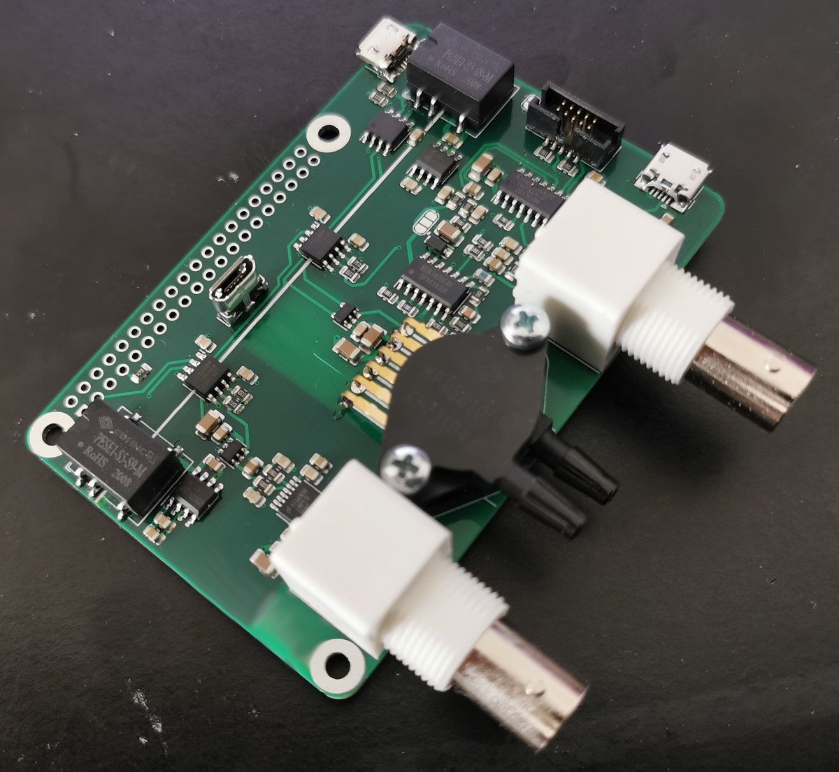
Picture above shows V3.0 - New version has some changes (e.g. pinheaders for I2C and 1-wire):
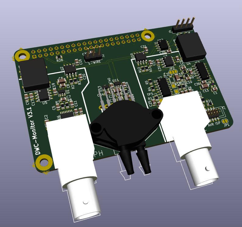
The DWC Hat does following:
*: Everything except the pressure sensing works as expected. It works electrically, but there would be needed a much more sophisticated temperature compensation. To sum it up: It never worked well.
Use raspi-config to enable I2C and 1-Wire.
There is a special quirk needed for getting the I2C working properly (because the Pi can't do clock-stretching):
In /boot/config.txt:
# Uncomment some or all of these to enable the optional hardware interfaces
dtparam=i2c_baudrate=10000
It hurts a bit to reduce the I2C rate to 10kHz - but it doesn't really matter :shrug:
Also, the 1-wire pin needs to be configured:
# select 1-wire pin
dtoverlay=w1-gpio,gpiopin=4,pullup=onThere are four I2C and one 1-wire device.
i2cdetect -y 1:

     0  1  2  3  4  5  6  7  8  9  a  b  c  d  e  f
00:          -- -- -- -- -- -- -- -- -- -- -- -- --
10: 10 -- -- -- -- -- -- -- -- -- -- -- -- -- -- --
20: -- -- -- -- -- -- -- -- -- -- -- -- -- -- -- --
30: -- -- -- -- -- -- -- -- -- -- -- -- -- -- -- --
40: 40 -- -- -- -- -- -- -- -- -- -- -- -- 4d -- --
50: -- -- -- -- -- -- -- -- -- -- -- -- -- -- -- --
60: -- -- -- -- -- -- -- -- -- -- 6a -- -- -- -- --
70: -- -- -- -- -- -- -- --
0x10: EC measurement (fixed by AVR firmware) 0x40: SI7021 temperature and humidity sensor 0x4d: MPX2050DP pressure sensor (ADC MCP3221) 0x6a: PH measurement (ADC MCP3421)
The addresses can differ (e.g. the ADC used in the PH measurement could be either of 0x68 to 0x6f).
Please check the datasheets of the parts mentioned above and/or i2cdetect for the address of your part.
The values are inserted into the config.ini:
[i2c]
# i2c address of EC measuring (always 0x10)
i2c_ec = 0x10

# i2c address of PH measuring
i2c_ph = 0x6a

# i2c address of MPX2050DP
i2c_pressure = 0x4d

# i2c address of SI7021
i2c_ht = 0x40After connecting the 1-wire sensor, there should appear a new device at /sys/bus/w1/devices/.
Add the name to the config.ini:
[1wire]
ds18b20 = "28-0120625ed8f9"The EC-measuring part uses an AVR. Before doing measurements, it needs to be flashed with the firmware.
The ISP connector is 2x10 with 1.27mm pitch. The pinout is compatible to the USBASP.
Also the Makefile expects the USBASP as programmer.
For compilation, you'll need:
sudo apt install gcc-avr avrdude avr-libcAfter that, first initialize the AVR-flags once with:
make fuseAfterwards you can compile and flash the AVR with:
make
make flash
Now, it should be ready to go :slight_smile:
There are two parts that need calibration. (See usage how to get the raw-values).
PH calibration is done by setting up two reference solutions with PH of 4.01 and 6.86.
After measuring the raw-values, insert them into the config.ini:
[ph]
# measured PH (raw values)
PH_401 =  13010.0
PH_686 = 2400.0For calibrating the EC part, two resistors are needed.
They are simply connected to the BNC jack for the EC probe (without the probe) and the raw-values measured by the EC measuring circuit is used for calculating the EC.
The resistors are 390R and 1k.
The values have to be inserted into the config.ini:
[ec]
# measured EC (raw values)
EC_ADC_390R = 439.0
EC_ADC_1K = 208.0By default, the python code does a single measurement and transmitts the date to InfluxDB.
To run it in a loop simply start it in a screen session with:
 while ((1)); do python3 read.py | tee -a measurements.log ; sleep 1; done

time=1635402997671, ec_raw=243.3764705882353, ec=1345.546146, ph_raw=6772, ph=5.685617, temp=20.875000, pressure_raw=122.5625, pressure_comp=44.20985378262856, humidity=68.68032836914062, airtemp=22.873859863281247
...Follow any tutorial for installing InfluxDB and Grafana.
Default Database, User, Password is in the config.ini.
Make sure to configure the timezone right on the Raspi.
There are some things I would like to improve:
Use everything on your own risk!
The project is at it is and if I don't need something else, I won't touch it ever again.
Feel free to do with it whatever you like :slight_smile:
| Qty | Value | Footprint | References |
|---|---|---|---|
| 21 | 100n | Capacitor_SMD:C_0805_2012Metric | C1, C10, C11, C12, C15, C16, C17, C18, C20, C21, C23, C28, C30, C31, C34, C35 +5 |
| 7 | 1k | Resistor_SMD:R_0805_2012Metric | R1, R7, R8, R9, R10, R21, R23 |
| 7 | 1µ | Capacitor_SMD:C_0805_2012Metric | C3, C9, C14, C26, C27, C37, C40 |
| 6 | 2k2 | Resistor_SMD:R_0805_2012Metric | R2, R3, R12, R13, R24, R25 |
| 5 | 10µ | Capacitor_SMD:C_1206_3216Metric | C2, C6, C13, C29, C33 |
| 4 | 100k | Resistor_SMD:R_0805_2012Metric | R4, R5, R6, R16 |
| 4 | TestPoint | TestPoint:TestPoint_Pad_1.5x1.5mm | TP1, TP2, TP3, TP4 |
| 3 | 4.7k | Resistor_SMD:R_0805_2012Metric | R18, R19, R26 |
| 2 | 0509 | myfootprints:Converter_DCDC_SMD | U4, U8 |
| 2 | 100n/25V | Capacitor_SMD:C_0805_2012Metric | C19, C32 |
| 2 | 10k | Resistor_SMD:R_0805_2012Metric | R20, R22 |
| 2 | 47n | Capacitor_SMD:C_0805_2012Metric | C7, C22 |
| 2 | ADUM1251 | Package_SO:SOIC-8_3.9x4.9mm_P1.27mm | U2, U10 |
| 2 | BNC | myfootprints:BNC_UG_1094W1 | P1, P4 |
| 2 | L78L05_SO8 | Package_SO:SOIC-8_3.9x4.9mm_P1.27mm | U3, U5 |
| 2 | Net-Tie_2 | NetTie:NetTie-2_SMD_Pad0.5mm | NT1, NT2 |
| 1 | 20k | Resistor_SMD:R_0805_2012Metric | R15 |
| 1 | 22n | Capacitor_SMD:C_0805_2012Metric | C24 |
| 1 | 3.3k | Resistor_SMD:R_0805_2012Metric | R11 |
| 1 | 33n | Capacitor_SMD:C_0805_2012Metric | C25 |
| 1 | 470p | Capacitor_SMD:C_0805_2012Metric | C39 |
| 1 | 5.1k | Resistor_SMD:R_0805_2012Metric | R14 |
| 1 | 8.2k | Resistor_SMD:R_0805_2012Metric | R17 |
| 1 | 8MHz | Oscillator:Oscillator_SMD_EuroQuartz_XO32-4Pin_3.2x2.5mm | X1 |
| 1 | ATTINY84A-SS | Package_SO:SO-14_3.9x8.65mm_P1.27mm | IC3 |
| 1 | BAT54T1G | Diodes_SMD:SOD-123 | D1 |
| 1 | Conn_01x03 | Connector_PinHeader_2.54mm:PinHeader_1x03_P2.54mm_Vertical | J2 |
| 1 | Conn_01x04 | Connector_PinHeader_2.54mm:PinHeader_1x04_P2.54mm_Vertical | J4 |
| 1 | Conn_02x05_Odd_Even | myfootprints:PinHeader_IDC_2x05_P1.27mm_Vertical_SMD | J3 |
| 1 | Jumper_3_Open | Jumper:SolderJumper-3_P1.3mm_Open_RoundedPad1.0x1.5mm | JP2 |
| 1 | Jumper_NO_Small | Jumper:SolderJumper-2_P1.3mm_Open_RoundedPad1.0x1.5mm | JP1 |
| 1 | LMP91200 | Package_SO:TSSOP-16_4.4x5mm_P0.65mm | U6 |
| 1 | MCP1541-TT | Package_TO_SOT_SMD:SOT-23 | U13 |
| 1 | MCP3221 | Package_TO_SOT_SMD:SOT-23-5 | U11 |
| 1 | MCP3421 | Package_TO_SOT_SMD:SOT-23-6 | U1 |
| 1 | MPX5010DP | myfootprints:MPX5010DP | U9 |
| 1 | OPA4340 | Package_SO:SO-14_3.9x8.65mm_P1.27mm | U7 |
| 1 | PCA9515 | Package_SO:SO-8_3.9x4.9mm_P1.27mm | U12 |
| 1 | Raspberry Pi GPIO | Connector_PinSocket_2.54mm:PinSocket_2x20_P2.54mm_Vertical | J1 |
The 96 most common of 100 parts.

xmyoot/guarded-ph-acquisition-module
Guarded pH analog front end: KiCad design, fabrication files, ESP32-S3 bring-up firmware and engineering review. Unbuilt prototype.

jayis1/hardware-design-lab
Full-cycle hardware device designs — each device in its own subfolder with architecture, schematics, PCB layout, and software stack


Ardumower/ardumower
Develop an open source robotic lawn mower (HW+SW reference platform)


ciaa/Ponchos
El poncho consta de elemento digitales y analógicos tales como: potenciómetro, buzzer, UART/RS-232, LCD 16x2, teclado matricial 4x3, y pinout para comunicaciones varias y pines de propósito general.

EPFLXplore/Power_HW
KiCad design files for the power boards of the Xplore rover.
It measures 85 × 56 mm and has 4 copper layers, 1.6 mm thick.
100 parts, built around the ATTINY84A-SSF, MCP3221A5-E, MPX5010DP and OPA4340UA. The full list of its parts is on this page, with links to each part's symbol and footprint where PCBKit's library has them.
From the dwcguru1/dwc-hat repository on GitHub, at the commit this page was made from: the board is kicad/dwc-hat.kicad_pcb. PCBKit opens the board in the browser, with nothing to install.
Its repository publishes it under the MIT licence: you may reuse it on that licence's terms (keep the author's notice, and for a copyleft licence share your changes alike).