


2 layers50 × 40 mm

 Dominik-Workshop/lap-timer
Lap timer, EKA 2 sem PWR
Receiver board is an open-source printed circuit board by Dominik-Workshop, from the Dominik-Workshop/lap-timer repository on GitHub, published under the GPL-3.0 licence. It is a 2-layer board of 16.5 × 19.7 mm with 5 parts on 5 nets, routed with 11 tracks and 0 vias.
It is built around the TSSP58038 and PJ-342. Its parts include 1 capacitor, 1 IC and 1 connector. It belongs with the STM32 boards of this library.

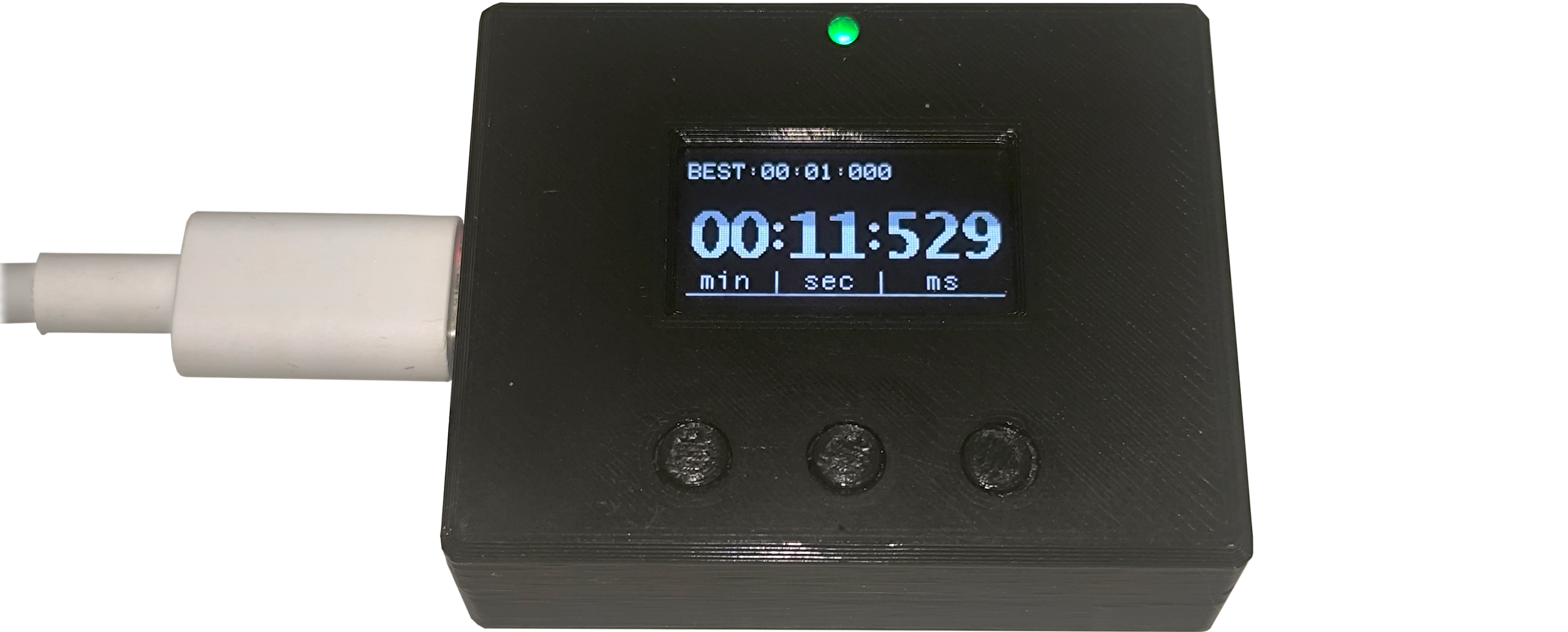
Compact and portable lap timer, capable of measuring time on:
Infrared light barriers are used as optical triggers to detect when an object crosses the start or finish line.
Design: ✅ --> Fabrication & Assembly: ✅ --> Bring-up: ✅
Simplified arhitecture of the Lap Timer is shown on the block diagram bellow:

This project contains 3 custom PCBs:
Each board has a custom-designed 3D printed enclosure.
| Qty | Value | Footprint | References |
|---|---|---|---|
| 1 | C-1u-0402 | Capacitor_SMD:C_0402_1005Metric | C6 |
| 1 | Jack_PJ-342 | Connector_JAE:Jack_PJ-342 | J2 |
| 1 | TSSP58038 | OptoDevice:Vishay_MINICAST-3Pin | U2 |
The 3 most common of 5 parts.
It measures 16.5 × 19.7 mm and has 2 copper layers, 1.6 mm thick.
5 parts, built around the TSSP58038 and PJ-342. The full list of its parts is on this page, with links to each part's symbol and footprint where PCBKit's library has them.
From the Dominik-Workshop/lap-timer repository on GitHub, at the commit this page was made from: the board is pcb/receiver-board/receiver-board.kicad_pcb and its schematic pcb/receiver-board/receiver-board.kicad_sch. PCBKit opens the board in the browser, with nothing to install.
Its repository publishes it under the GPL-3.0 licence: you may reuse it on that licence's terms (keep the author's notice, and for a copyleft licence share your changes alike).


KOEGlike/meko
A linux music player with ddr3, a 70hz e-paper display and a haptic touchpad

RADARC/Scout-Radio
Si4732 and Raspberry Pi Pico Radio device for Scouts to build and use to gain badges


mojo626/iPodClone
This is a clone of an iPod video based on the Allwinner V3s processor


dotcypress/ir-smart-led-controller
IR Remote Controller for WS2812(or analog) LED Strip

XasWorks/dragon-home
A rework of our old SmartHome project, this time done cleanly and neatly~