4 layers11.2 × 25.4 mm

 domesticmouse/BufferedMult-SKiDL
A BufferedMult made with SKiDL
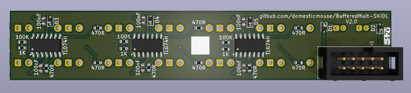
BufferedMult is an open-source printed circuit board by domesticmouse, from the domesticmouse/BufferedMult-SKiDL repository on GitHub, published under the Apache-2.0 licence. It is a 2-layer board of 20 × 109 mm with 44 parts on 32 nets, routed with 170 tracks and 24 vias.
It is built around the TL074HID, CC0603KRX7R9BB104 and PESD12VL1BA,115-ES, with the ECEA1EKS100 and 1N5819WS among its other parts. Its parts include 15 resistors, 13 connectors, 8 capacitors, 5 diodes and 3 ICs.


A precision Triple 1-to-3 (Normalized to 1-to-6 / 1-to-9) Eurorack Buffered Multiple designed in Python using SKiDL and targeting KiCad 10.
This project is a SKiDL re-implementation and 3-channel expansion of domesticmouse/Buffered-Mult, omitting the LED feedback circuitry.
Interactive Course & Tutorial: https://domesticmouse.github.io/BufferedMult-SKiDL/ (published via GitHub Pages from tutorial/)
IN_1) driving 3 individually buffered outputs (OUT_1A, OUT_1B, OUT_1C). When IN_1 is unpatched, its normalled switch contact (TN) grounds the input to 0V.IN_2) driving 3 individually buffered outputs (OUT_2A, OUT_2B, OUT_2C). When IN_2 is unpatched, its normalled switch contact (TN) receives the buffered signal from Channel 1 (CH1_BUF), cascading Channels 1 and 2 into a 1-to-6 buffered multiple with zero loading droop between channels. Patching a cable into IN_2 breaks the normal connection for independent channel operation.IN_3) driving 3 individually buffered outputs (OUT_3A, OUT_3B, OUT_3C). When IN_3 is unpatched, its normalled switch contact (TN) receives the buffered signal from Channel 2 (CH2_BUF), cascading all three channels into a 1-to-9 buffered multiple (or a 1-to-3 + 1-to-6 split if IN_2 is patched while IN_3 is unpatched). Patching a cable into IN_3 breaks the normal connection for independent triple 1-to-3 operation.TL074H (TL074HIDR) op-amp (SOIC-14):
PESD12VL1BA (SOD-323) bidirectional 12V TVS/ESD diode, a 100K input pull-down resistor (0603), and a 1K series input current-limiting resistor (0603).470R series output protection resistor (0603).2x5) through-hole shrouded IDC power header (±12V, GND).1N5819WS Schottky diodes (SOD-323, or B5819W in SOD-123 as a larger alternative).10uF radial through-hole electrolytic bulk bypass capacitors per rail plus 100nF (0603) local ceramic decoupling capacitors at each op-amp's V+ and V- pins.flowchart LR
subgraph CH1["Channel 1 (U1: TL074H)"]
J_IN1["IN_1 Jack<br/>(TN -> GND)"] --> TVS1["PESD12VL1BA TVS<br/>+ 100K to GND"]
TVS1 --> R_IN1["1K Series"] --> U1A["U1A Input Buffer"]
U1A --> U1B["U1B Buffer + 470R"] --> OUT_1A["OUT_1A Jack"]
U1A --> U1C["U1C Buffer + 470R"] --> OUT_1B["OUT_1B Jack"]
U1A --> U1D["U1D Buffer + 470R"] --> OUT_1C["OUT_1C Jack"]
end
subgraph CH2["Channel 2 (U2: TL074H)"]
J_IN2["IN_2 Jack<br/>(TN <- CH1_BUF)"] --> TVS2["PESD12VL1BA TVS<br/>+ 100K to GND"]
TVS2 --> R_IN2["1K Series"] --> U2A["U2A Input Buffer"]
U2A --> U2B["U2B Buffer + 470R"] --> OUT_2A["OUT_2A Jack"]
U2A --> U2C["U2C Buffer + 470R"] --> OUT_2B["OUT_2B Jack"]
U2A --> U2D["U2D Buffer + 470R"] --> OUT_2C["OUT_2C Jack"]
end
subgraph CH3["Channel 3 (U3: TL074H)"]
J_IN3["IN_3 Jack<br/>(TN <- CH2_BUF)"] --> TVS3["PESD12VL1BA TVS<br/>+ 100K to GND"]
TVS3 --> R_IN3["1K Series"] --> U3A["U3A Input Buffer"]
U3A --> U3B["U3B Buffer + 470R"] --> OUT_3A["OUT_3A Jack"]
U3A --> U3C["U3C Buffer + 470R"] --> OUT_3B["OUT_3B Jack"]
U3A --> U3D["U3D Buffer + 470R"] --> OUT_3C["OUT_3C Jack"]
endThe design separates SMT components (factory-assembled on B.Cu by JLCPCB) from Through-Hole (THT) components (hand-soldered after receiving the boards):
| Ref | Qty | Value / Part | Package / Footprint | KiCad Symbol | LCSC Part # | Assembly / Description |
|---|---|---|---|---|---|---|
U1–U3 | 3 | TL074H (TL074HIDR) | Package_SO:SOIC-14_3.9x8.7mm_P1.27mm | Amplifier_Operational:TL074 | C2878713 | SMT (B.Cu, Extended) — Quad Low-Noise High-Voltage Op-Amp |
D1, D2 | 2 | 1N5819WS | Diode_SMD:D_SOD-323 | Device:D_Schottky | C191023 | SMT (B.Cu, Basic) — Schottky Reverse-Polarity Protection Diode (Alt larger package: B5819W in Diode_SMD:D_SOD-123, LCSC C8598, Basic) |
D3–D5 | 3 | PESD12VL1BA (PESD12VL1BA,115) | Diode_SMD:D_SOD-323 | Device:D_TVS | C38558 | SMT (B.Cu, Extended) — 12V Bidirectional Low-Capacitance (19 pF, <50 nA) Input ESD/TVS Protection Diode (Alt 15V: PESD15VL1BA,115 / C85378; Basic SOD-123FL: SMF12CA / C19077508) |
C3–C8 | 6 | 100nF (50V X7R) | Capacitor_SMD:C_0603_1608Metric | Device:C | C14663 | SMT (B.Cu, Basic) — Ceramic Decoupling Capacitor (CC0603KRX7R9BB104) |
R1, R6, R11 | 3 | 100K (1%) | Resistor_SMD:R_0603_1608Metric | Device:R | C25803 | SMT (B.Cu, Basic) — Input Pull-Down Resistor (0603WAF1003T5E) |
R2, R7, R12 | 3 | 1K (1%) | Resistor_SMD:R_0603_1608Metric | Device:R | C21190 | SMT (B.Cu, Basic) — Input Series Overvoltage / ESD Current-Limiting Resistor (0603WAF1001T5E) |
R3–R5, R8–R10, R13–R15 | 9 | 470R (1%) | Resistor_SMD:R_0603_1608Metric | Device:R | C23179 | SMT (B.Cu, Basic) — Output Series Protection Resistor (0603WAF4700T5E) |
J2–J13 | 12 | WQP-PJ398SM | Connector_Audio:Jack_3.5mm_QingPu_WQP-PJ398SM_Vertical_CircularHoles | Connector_Audio:AudioJack2_SwitchT | — | THT (F.Cu, Hand-Soldered) — 3.5mm Mono Switched Eurorack Jack (Thonkiconn) |
C1, C2 | 2 | 10uF (25V) | Capacitor_THT:CP_Radial_D5.0mm_P2.00mm | Device:C_Polarized | C713347 | THT (F.Cu, Hand-Soldered) — Radial Electrolytic Bulk Cap (ECEA1EKS100) |
J1 | 1 | EURORACK_PWR_10PIN | Connector_IDC:IDC-Header_2x05_P2.54mm_Vertical | Connector_Generic:Conn_02x05_Odd_Even | — | THT (B.Cu, Hand-Soldered) — 10-Pin (2x5) Shrouded Eurorack Power Header |
/Applications/KiCad/KiCad.app/Contents/SharedSupport/ is detected automatically by buffered_multiple.py).uv.Create the virtual environment and install dependencies:
uv venv --clear --python 3.14 .venv
uv pip install skidl markdown-it-py pyyaml
Generate the circuit outputs and run Electrical Rules Checking (ERC):
.venv/bin/python buffered_multiple.pyGenerate or update the 4HP Eurorack front panel PCB and Gerbers:
/Applications/KiCad/KiCad.app/Contents/Frameworks/Python.framework/Versions/Current/bin/python3 \
    .agents/skills/eurorack-panel/scripts/generate_eurorack_panel.py \
    --main-pcb BufferedMult.kicad_pcb \
    --output BufferedMult_Panel.kicad_pcb \
    --title "BUF MULT" \
    --subtitle "1:3 / 1:6 / 1:9" \
    --gerber-dir production/panel \
    --zip production/BufferedMult_Panel.zip \
    --drc
Build and validate the interactive tutorial HTML from Markdown (optional, for local previewing; GitHub Actions automatically builds and publishes to GitHub Pages via .github/workflows/pages.yml):
.venv/bin/python tutorial/build.py --checkLint and format with ruff:
ruff check --fix buffered_multiple.py buffered_multiple_sklib.py tutorial/build.py && ruff format buffered_multiple.py buffered_multiple_sklib.py tutorial/build.pyRunning buffered_multiple.py produces:
buffered_multiple.net — KiCad 10 netlist with deterministic hierarchical tstamps and Power / Signal net classes.buffered_multiple_bom.xml — KiCad XML Bill of Materials.buffered_multiple_jlcpcb_bom.csv — Grouped JLCPCB SMT PCBA Bill of Materials (Comment,Designator,Footprint,LCSC Part #), excluding hand-soldered THT parts by default.buffered_multiple.erc / buffered_multiple.log — SKiDL ERC report and execution log (0 errors, 0 warnings).buffered_multiple_sklib.py — Auto-generated SKiDL backup symbol library.Both the main circuit board and a mated 3U × 4HP Eurorack front panel are included in the repository:
BufferedMult.kicad_pro / BufferedMult.kicad_pcb):
20.0 × 109.0 mm (4HP, Rev V2.0), 2-layer PCB with stitched F.Cu and B.Cu GND planes and 0.5 mm ±12V power spines.B.Cu (29 SMD parts) and hand-soldered THT jacks/bulk caps on F.Cu (J2–J13, C1, C2) plus the 10-pin power header on B.Cu (J1), complete with a -12V orientation knockout, V2.0 revision marking, and repository URL on B.SilkS.BufferedMult_Panel.kicad_pro / BufferedMult_Panel.kicad_pcb):
20.0 × 128.5 mm (Doepfer A-100 3U × 4HP standard).6.2 mm PTH grounded jack cutouts aligned to the +6.48 mm WQP-PJ398SM (Thonkiconn) bushing centers (14.40 mm uniform vertical row pitch), 2× 3.2 × 5.5 mm NPTH M3 mounting slots, exposed F.Mask copper/finish graphics (BUF MULT title, input callout badges for IN 1 / IN 2 / IN 3, and normalling cascade indicators), F.SilkS jack labels and TL074 callout, and solid F.Cu / B.Cu copper shield planes with exposed rear ground rings.production/):
production/BufferedMult.zip — Main PCB Gerbers and Excellon drill files.production/BufferedMult_Panel.zip — 4HP Front Panel Gerbers and Excellon drill files (also unpacked in production/panel/).production/positions.csv, production/bom.csv, production/designators.csv, production/netlist.ipc — Fabrication Toolkit pick-and-place, BOM, and IPC-D-356 netlist files (use buffered_multiple_jlcpcb_bom.csv for SMT-only JLCPCB assembly).tutorial/)The repository includes an 8-lesson interactive Hardware-as-Code course published at https://domesticmouse.github.io/BufferedMult-SKiDL/ (authored in Markdown under tutorial/ and compiled via tutorial/build.py). Starting from an empty Python file, the lessons progressively grow buffered_multiple.py and its post-netlist PCB, front-panel, and pre-fab verification scripts:
| Lesson | Stage & Title | Markdown Source | Runnable Companion App |
|---|---|---|---|
0001 | Stage 1: From an Empty File to KiCad 10 Bootstrap & First ERC() (0 → 72 lines) | 0001-environment-and-kicad-bootstrap.md | bootstrap_check.py |
0002 | Stage 2: Programmatic Part Discovery & Adding FP_* / LCSC_* Constants | 0002-programmatic-component-discovery.md | discover_parts.py |
0003 | Stage 3: Growing the Script — Adding eurorack_power(vcc, vee, gnd) (68 → 155 lines) | 0003-eurorack-power-subcircuit.md | power_subcircuit.py |
0004 | Stage 4: Growing the Script — Adding buffered_channel_1to3() (155 → 255 lines) | 0004-single-buffered-channel.md | single_channel.py |
0005 | Stage 5: Completing buffered_multiple.py — Cascaded Normalling (1:3 → 1:6 → 1:9), NetClass & JLCPCB BOM (255 → 334 lines) | 0005-cascaded-normalling-and-bom-export.md | buffered_multiple.py |
0006 | Stage 6: From .net Netlist to 4HP KiCad 10 PCB Layout & Single-Sided SMT Assembly | 0006-kicad-pcb-layout-and-assembly.md | inspect_netlist_and_layout.py |
0007 | Stage 7: Automated 4HP Eurorack Front Panel Generation in Python (+6.48 mm Bushing Offset) | 0007-eurorack-front-panel-generator.md | generate_panel_plan.py |
0008 | Stage 8 (Capstone): Programmatic Pre-Fab Design Review — Netlist-to-PCB Audit, DRC & Gerber Verification (5/5 checks) | 0008-prefab-design-review-and-drc.md | prefab_design_audit.py |
tutorial/reference/)skidl-cheatsheet.md — SKiDL API, pre-import KiCad 10 configuration, dest=TEMPLATE, part.fields, u.p[n] vs u["V+"], @subcircuit, NetClass, and ERC() syntax cheat sheet.kicad-jlcpcb-lookup.md — Four-step programmatic component discovery workflow (search, show, search_footprints, jlcpcb_search.py) and verified BOM pinout/LCSC table.eurorack-power-and-normalling.md — Doepfer A-100 10-pin power header pinout, Schottky & bulk capacitor polarity, WQP-PJ398SM switched jack mechanics, and the 1:3 / 1:6 / 1:9 normalling truth table.GLOSSARY.md — Standardized SKiDL, KiCad 10, JLCPCB PCBA, and Eurorack hardware terminology.domesticmouse.github.io/BufferedMult-SKiDL) — Hosted HTML edition of the 8-lesson (0001–0008) course and 4 reference sheets, built automatically by .github/workflows/pages.yml.PCB_LAYOUT_GUIDE.md — Step-by-step KiCad 10 PCB layout, component placement, routing, and JLCPCB export guide.FRONT_PANEL_GUIDE.md — 4HP Eurorack front panel mechanical dimensions, bushing offset coordinate table, and automated generation workflow.DESIGN_REVIEW.md — Full schematic, PCB, DRC, Gerber, and EMC pre-compliance design review report.Licensed under the Apache License, Version 2.0. See LICENSE.txt for details.
This is not an official Google product.
| Qty | Value | Footprint | References |
|---|---|---|---|
| 9 | 470R | Resistor_SMD:R_0603_1608Metric | R3, R4, R5, R8, R9, R10, R13, R14, R15 |
| 6 | 100nF | Capacitor_SMD:C_0603_1608Metric | C3, C4, C5, C6, C7, C8 |
| 3 | 100K | Resistor_SMD:R_0603_1608Metric | R1, R6, R11 |
| 3 | 1K | Resistor_SMD:R_0603_1608Metric | R2, R7, R12 |
| 3 | PESD12VL1BA | Diode_SMD:D_SOD-323 | D3, D4, D5 |
| 3 | TL074H | Package_SO:SOIC-14_3.9x8.7mm_P1.27mm | U1, U2, U3 |
| 2 | 10uF | Capacitor_THT:CP_Radial_D5.0mm_P2.00mm | C1, C2 |
| 2 | 1N5819WS | Diode_SMD:D_SOD-323 | D1, D2 |
| 1 | EURORACK_PWR_10PIN | Connector_IDC:IDC-Header_2x05_P2.54mm_Vertical | J1 |
| 1 | IN_1 | Connector_Audio:Jack_3.5mm_QingPu_WQP-PJ398SM_Vertical_CircularHoles | J2 |
| 1 | IN_2 | Connector_Audio:Jack_3.5mm_QingPu_WQP-PJ398SM_Vertical_CircularHoles | J6 |
| 1 | IN_3 | Connector_Audio:Jack_3.5mm_QingPu_WQP-PJ398SM_Vertical_CircularHoles | J10 |
| 1 | OUT_1A | Connector_Audio:Jack_3.5mm_QingPu_WQP-PJ398SM_Vertical_CircularHoles | J3 |
| 1 | OUT_1B | Connector_Audio:Jack_3.5mm_QingPu_WQP-PJ398SM_Vertical_CircularHoles | J4 |
| 1 | OUT_1C | Connector_Audio:Jack_3.5mm_QingPu_WQP-PJ398SM_Vertical_CircularHoles | J5 |
| 1 | OUT_2A | Connector_Audio:Jack_3.5mm_QingPu_WQP-PJ398SM_Vertical_CircularHoles | J7 |
| 1 | OUT_2B | Connector_Audio:Jack_3.5mm_QingPu_WQP-PJ398SM_Vertical_CircularHoles | J8 |
| 1 | OUT_2C | Connector_Audio:Jack_3.5mm_QingPu_WQP-PJ398SM_Vertical_CircularHoles | J9 |
| 1 | OUT_3A | Connector_Audio:Jack_3.5mm_QingPu_WQP-PJ398SM_Vertical_CircularHoles | J11 |
| 1 | OUT_3B | Connector_Audio:Jack_3.5mm_QingPu_WQP-PJ398SM_Vertical_CircularHoles | J12 |
| 1 | OUT_3C | Connector_Audio:Jack_3.5mm_QingPu_WQP-PJ398SM_Vertical_CircularHoles | J13 |


It measures 20 × 109 mm and has 2 copper layers, 1.6 mm thick.
44 parts, built around the TL074HID, CC0603KRX7R9BB104, PESD12VL1BA,115-ES and ECEA1EKS100. The full list of its parts is on this page, with links to each part's symbol and footprint where PCBKit's library has them.
From the domesticmouse/BufferedMult-SKiDL repository on GitHub, at the commit this page was made from: the board is BufferedMult.kicad_pcb. PCBKit opens the board in the browser, with nothing to install.
Its repository publishes it under the Apache-2.0 licence: you may reuse it on that licence's terms (keep the author's notice, and for a copyleft licence share your changes alike).