4 layers11.2 × 25.4 mm

 Schenktronics/ST03-attenuverter
A 4 channel eurorack attenuverter
Attenuverter is an open-source printed circuit board by Schenktronics, from the Schenktronics/ST03-attenuverter repository on GitHub. It is a 2-layer board of 30 × 100 mm with 73 parts on 39 nets, routed with 454 tracks and 61 vias.
It is built around the TL074HID, LM4040D50IDBZR and 1N4148WS-7-F-CN. Its parts include 29 resistors, 13 capacitors, 11 diodes, 9 connectors and 2 ICs. It belongs with the audio and music boards of this library.


A 6HP Eurorack quad attenuverter from Schenktronics. Each of its four channels scales a signal anywhere from x1, through zero, to x-1 (inverted). Every input is normalled to +5 V, so with nothing plugged in, each channel is a manual offset from -5 V to +5 V.
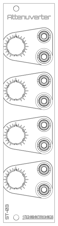
| Document | For | |
|---|---|---|
| User Manual | Using the module | |
| Assembly Guide | Building the kit | |
| Bill of Materials (CSV) | Parts and sourcing |
hardware/
  ST-03_Attenuverter.step          3D model of the assembled module
  attenuverter/                    Main PCB (KiCad 10)
    Attenuverter.kicad_sch           Schematic
    Attenuverter.kicad_pcb           PCB layout
    Attenuverter.step                3D model
    attenuverter BOM.xlsx            Original BOM spreadsheet
  panel/                           Faceplate (KiCad 10, made as an aluminum PCB)
    AttenuverterFaceplate.kicad_pcb  Faceplate layout
    AttenuverterFaceplate.step       3D model
docs/                              Manual, assembly guide, BOM, images
  pdf/                               PDF versions of the manual and assembly guide
The .github/ folder holds the automation that builds the PDFs. You can ignore it.
| Board | Size | Layers | Thickness | Notes |
|---|---|---|---|---|
| Main PCB | 30 x 100 mm | 2 | 1.6 mm | Standard green is fine. Surface-mount parts on the back. |
| Faceplate | 30 x 128.5 mm | 1 | 1.6 mm | Aluminum PCB, white solder mask, black silkscreen. Only the front copper layer is used, so FR4 works too. |
The BOM lists every part, including the surface-mount ones the kits ship with already soldered. The jack pads are oval so the board can also take panel-mount style jacks, which may be easier to source. The CUI MJ-3507 is one example: its sleeve is a solder lug rather than a pin, so each one needs a short wire from that lug to the jack's square pad.
This hardware design and its documentation are licensed under CC BY-NC-SA 4.0. See LICENSE.
The Schenktronics name and logo are trademarks of Schenktronics LLC and are not covered by the CC BY-NC-SA 4.0 license.
| Qty | Value | Footprint | References |
|---|---|---|---|
| 16 | 100k | Resistor_SMD:R_0805_2012Metric | R1, R2, R4, R5, R6, R7, R9, R10, R12, R13, R15, R16, R17, R18, R20, R21 |
| 13 | 1k | Resistor_SMD:R_0805_2012Metric | R3, R8, R11, R14, R19, R22, R23, R24, R25, R26, R27, R28, R29 |
| 9 | 1N4148WS-7-F | Diode_SMD:D_SOD-323 | D3, D4, D5, D6, D7, D8, D9, D10, D11 |
| 8 | 10pF | Capacitor_SMD:C_0805_2012Metric | C1, C2, C3, C7, C10, C11, C12, C13 |
| 8 | AudioJack2_SwitchT | _NTSFootprints:Jack_3.5mm_QingPu_WQP-PJ398SM_Vertical_CenterHole_OvalPads | J1, J2, J3, J4, J5, J6, J8, J9 |
| 4 | 100k | _NTSFootprints:Potentiometer_Alps_RK09L_Plated_Mount_Holes | RV1, RV2, RV3, RV4 |
| 3 | 100nF | Capacitor_SMD:C_0805_2012Metric | C4, C6, C9 |
| 3 | Fiducial_1mm_Mask2mm | Fiducial:Fiducial_1mm_Mask2mm | FID1, FID2, FID3 |
| 2 | 10uF | Capacitor_SMD:C_0805_2012Metric | C5, C8 |
| 2 | D | Diode_SMD:D_SMA | D1, D2 |
| 2 | Polyfuse | Fuse:Fuse_1206_3216Metric | F1, F2 |
| 1 | Conn_02x05_Odd_Even | _NTSFootprints:PinHeader_2x05_P2.54mm_Vertical_Shrouded | J7 |
| 1 | LM4040D50IDBZR | Package_TO_SOT_SMD:SOT-23 | U2 |
| 1 | TL074H | Package_SO:SOIC-14_3.9x8.7mm_P1.27mm | U1 |


antmicro/gpu-cluster-backplane
This project contains open hardware design files for a PCB supporting power distribution in a cluster composed of GPUs. This board has been derived from an open source d1600e-psu-breakout created by Antmicro.

alph4345/test
TrinketCore puts everything a small rechargeable gadget needs on one 40 × 60 mm board, ready to order assembled from PCBWay:

BenjaminJAnderson/CUBE
CUBE is a miniature, six-faced OLED display cube built from a stack of custom interconnected PCBs. The current design combines an ESP32-S2 motherboard, five further display boards, a magnet-held 3D-printed frame and…

HasiKe/Exhaust-Mic
Motorcycle Exhaust and Intake Microphone for best soud on Videos.
It measures 30 × 100 mm and has 2 copper layers, 1.6 mm thick.
73 parts, built around the TL074HID, LM4040D50IDBZR and 1N4148WS-7-F-CN. The full list of its parts is on this page, with links to each part's symbol and footprint where PCBKit's library has them.
From the Schenktronics/ST03-attenuverter repository on GitHub, at the commit this page was made from: the board is hardware/attenuverter/Attenuverter.kicad_pcb and its schematic hardware/attenuverter/Attenuverter.kicad_sch. PCBKit opens the board in the browser, with nothing to install.
Its repository states no licence, so its author keeps all rights: ask Schenktronics before reusing the design.