2 layers87 × 71 mm

 doc22940/self.kedtracker.drone1
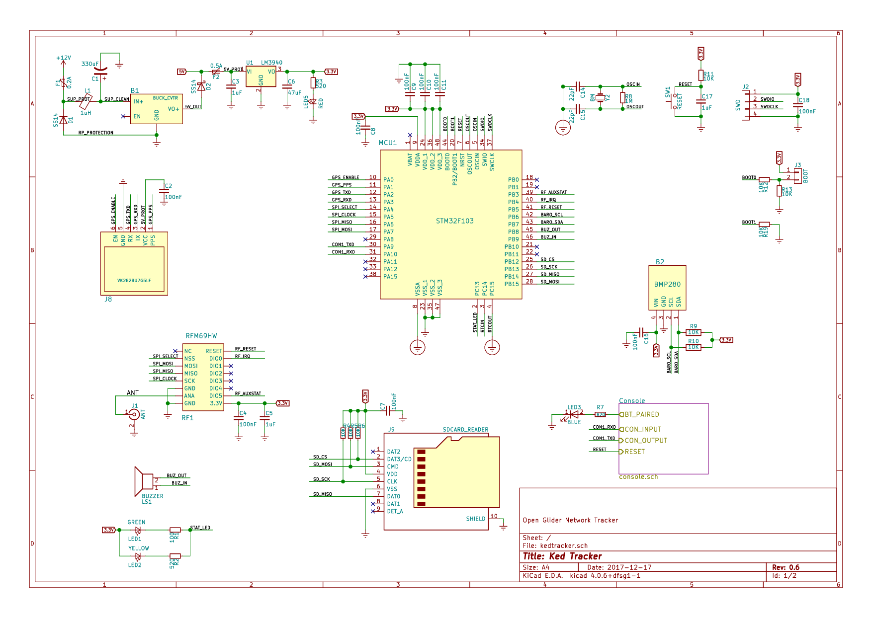
Based on design by glidernet.org project: http://wiki.glidernet.org/ogn-tracker-diy.
Kedtracker is an open-source printed circuit board by doc22940, from the doc22940/self.kedtracker.drone repository on GitHub. It is a 2-layer board of 82.7 × 56.6 mm with 86 parts on 63 nets, routed with 894 tracks and 147 vias.
It is built around the MAX3232ID, HC-05 and CH340G, with the BMP280, SS14 and RFM69HW among its other parts. Its parts include 25 capacitors, 19 resistors, 10 diodes, 9 connectors and 3 ICs. It belongs with the STM32 boards of this library.


Based on design by glidernet.org project: http://wiki.glidernet.org/ogn-tracker-diy.
It is a small airborn avionic device that periodically transmits aircraft position. Signal is picked up by ground-based receivers and published on Open Glider Network, so that aircraft position can be found on various aircraft tracking systems, like http://glidertracker.de/ or https://www.flightradar24.com/. It is also received by other OGN tracker devices in the vicinity and can be used to improve pilot' situation awareness. See http://wiki.glidernet.org/ for more information.
Ked Tracker is designed using KiCad electronic schematic and PCB design software.
Can be powered from onboard 12V power supply (or any 9-24V power supply for that matter).
Standard NMEA output.
Uses FLARM NMEA sentences to report detected nearby aircrafts for interoperability with existing hardware and software.
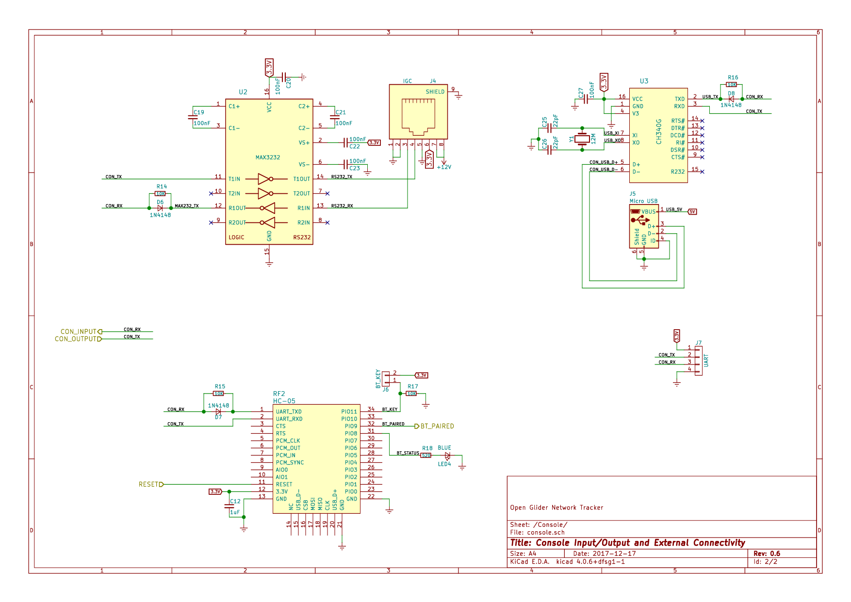
Communication via standard IGC RJ45 socket. Allows to re-use existing equipment like FLARM viewers or cables.
Communication via USB interface. Device is visible as virtual COM port when connected to a computer. Requires no special cables other then standerd micro-USB cable. Device can also be powered by 5V from USB interface.
Communication via Bluetooth. For hassle-free wireless connection with phone or tablet.
Barometric sensor onboard for more precise altitude measurement.
Slot for SD-card. Currently for logging device activity. Firmware for IGC flight logger is pending.
Beeper to provide sound feedback for important events.
Current schematics can be also downloaded in PDF format.
You will need to install additional packages for development. Packages for ubuntu are specified here; other operating systems might have similar requirements.
sudo apt install gcc-arm-none-eabi openocd picocom
sudo add-user `whoami` plugdev
sudo add-user `whoami` dialoutsudo apt install kicad| Qty | Value | Footprint | References |
|---|---|---|---|
| 15 | 100nF | Capacitors_SMD:C_0805 | C2, C4, C7, C8, C9, C10, C11, C16, C18, C19, C20, C21, C22, C23, C27 |
| 13 | 10K | Resistors_SMD:R_0805 | R4, R5, R6, R9, R10, R11, R12, R13, R14, R15, R16, R17, R19 |
| 4 | 1uF | Capacitors_SMD:C_1206 | C3, C5, C12, C17 |
| 4 | 22pF | Capacitors_SMD:C_0603 | C14, C15, C25, C26 |
| 3 | 1N4148 | Diodes_SMD:D_1206 | D6, D7, D8 |
| 3 | 520 | Resistors_SMD:R_0805 | R2, R3, R18 |
| 2 | SS14 | Diodes_SMD:D_SMA_Standard | D1, D2 |
| 1 | 0.2A | Fuse_Holders_and_Fuses:Fuse_SMD1206_Reflow | F1 |
| 1 | 0.5A | Fuse_Holders_and_Fuses:Fuse_SMD1206_Reflow | F2 |
| 1 | 100 | Resistors_SMD:R_0805 | R1 |
| 1 | 12M | Crystals:Crystal_HC49-4H_Vertical | Y1 |
| 1 | 1M | Resistors_SMD:R_0805 | R8 |
| 1 | 1uH | Inductors:INDUCTOR_V | L1 |
| 1 | 330uF | Capacitors_ThroughHole:CP_Radial_D6.3mm_P2.50mm | C1 |
| 1 | 47uF | Capacitors_SMD:C_1210 | C6 |
| 1 | 820 | Resistors_SMD:R_0805 | R7 |
| 1 | 8M | Crystals:Crystal_SMD_HC49-SD | Y2 |
| 1 | ANT | Ked Tracker:SMA_CONN | J1 |
| 1 | BLUE | LEDs:LED_0603 | LED4 |
| 1 | BLUE | LEDs:LED_D5.0mm_Horizontal_O3.81mm_Z3.0mm | LED3 |
| 1 | BMP280 | Ked Tracker:BMP280 | B2 |
| 1 | BOOT | Pin_Headers:Pin_Header_Straight_2x01_Pitch2.54mm | J3 |
| 1 | BT_KEY | Pin_Headers:Pin_Header_Straight_2x01_Pitch2.54mm | J6 |
| 1 | BUCK_CVTR | Ked Tracker:Buck_Converter_Sm | B1 |
| 1 | BUZZER | Buzzers_Beepers:Buzzer_12x9.5RM7.6 | LS1 |
| 1 | CH340G | Housings_SOIC:SOIC-16_3.9x9.9mm_Pitch1.27mm | U3 |
| 1 | GREEN | LEDs:LED_D5.0mm_Horizontal_O3.81mm_Z3.0mm | LED1 |
| 1 | HC-05 | Ked Tracker:HC-05 | RF2 |
| 1 | IGC | Ked Tracker:RJ45_SOCKET_SHLD | J4 |
| 1 | LM3940 | TO_SOT_Packages_SMD:SOT-223-3Lead_TabPin2 | U1 |
| 1 | MAX3232 | Housings_SOIC:SOIC-16_3.9x9.9mm_Pitch1.27mm | U2 |
| 1 | Micro USB | Ked Tracker:USB_Micro | J5 |
| 1 | RED | LEDs:LED_0603 | LED5 |
| 1 | RESET | Buttons_Switches_SMD:SW_SPST_SKQG | SW1 |
| 1 | RFM69HW | Ked Tracker:RFM69HW | RF1 |
| 1 | SDCARD_READER | Ked Tracker:SDCARD_BOMB | J9 |
| 1 | STM32F103 | Housings_QFP:LQFP-48_7x7mm_Pitch0.5mm | MCU1 |
| 1 | SWD | Pin_Headers:Pin_Header_Straight_1x04_Pitch2.54mm | J2 |
| 1 | UART | Pin_Headers:Pin_Header_Straight_1x04_Pitch2.54mm | J7 |
| 1 | VK2828U7G5LF | Ked Tracker:Molex_PicoBlade_53047-0610_06x1.25mm_Straight | J8 |
| 1 | YELLOW | LEDs:LED_0603 | LED2 |
The 78 most common of 86 parts.

d-diot/Mini-BT-Pcb-328P
MySensors ATMega328P + RFM69 and NRF24 battery (AAA and CR2032) powered pcb


clover-clever/NuBiHo_Quad_Drone
Microprocessor Quad Drone System, based on SPRacing R3 w/Arduino PPM Control Signal

MAATHES-THILAK-K/Arduino-SMD
Arduino SMD version with In-Built Bluetooth and Gesture sensor

Himanshukohale22/Flight_control_controller_V1.2
Hardware files for universal flight controller for small UAV's.

Gupatron/Gupsfirstpcb
This is the first pcb that I will manufacture and intend to use for teleop usecases in my personal projects.

It measures 82.7 × 56.6 mm and has 2 copper layers, 1.6 mm thick.
86 parts, built around the MAX3232ID, HC-05, CH340G and BMP280. The full list of its parts is on this page, with links to each part's symbol and footprint where PCBKit's library has them.
From the doc22940/self.kedtracker.drone repository on GitHub, at the commit this page was made from: the board is hardware/kedtracker.kicad_pcb. PCBKit opens the board in the browser, with nothing to install.
Its repository states no licence, so its author keeps all rights: ask doc22940 before reusing the design.