
2 layers26.4 × 36.1 mm
Sensof ht
dimhoff/sensof
Si4010 based wireless sensors(temperature, humidity, etc.) firmware and utilities
24 parts1
 dimhoff/sensof1
Si4010 based wireless sensors(temperature, humidity, etc.) firmware and utilities
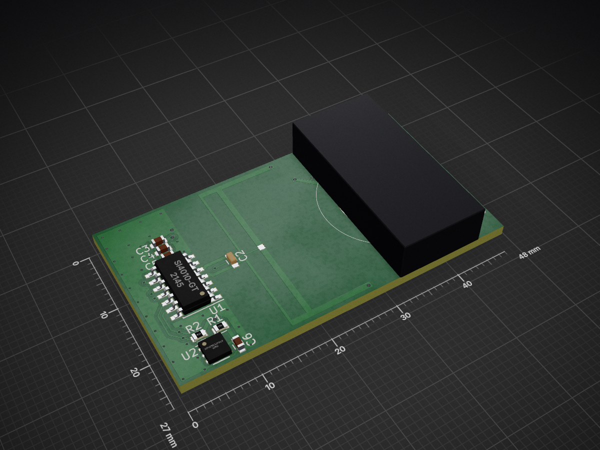
Sensof ht is an open-source printed circuit board by dimhoff, from the dimhoff/sensof repository on GitHub. It is a 2-layer board of 48 × 27 mm with 22 parts on 13 nets, routed with 124 tracks and 48 vias.
It is built around the CR2032. Its parts include 6 capacitors, 2 resistors, 2 ICs and 1 inductor.
Si4010 based wireless sensors(temperature, humidity, etc.) firmware and utilities.
Project status: This project is not actively maintained other then some minor fixes to keep it working for myself.
Sensof-HT is a temperature and humidity sensor that is build using a Si4010 MCU and a HTU21 sensor.
The Si4010 connects to a HTU21D, Si7020 or compatible sensor through I2C. The I2C bus is connected to the Si4010 on the following pins:
GPIO1 = SCL GPIO2 = SDA
Voltage level should be between 3.6 - 1.9 Volt. A 3V CR2032 works fine.
Some ready made Si4010 and HTU21D or Si7020 sensor are available on the internet. These only need to be connected together and connected to a battery.
This repository also contains a custom Sensof-HT PCB. However this is currently still under development. See hardware/README.md for more information.
The system uses the following modulation/encoding settings:
I use a RFM22B module, which is based on the Si4430 transceiver, connected to a Raspberry Pi for receiving the signal. The source code of the receiving program is available in the software/si443x_sensof directory.
I also did some experiments with a SX1231 based module. Which seem to have a better reception. I don't have any example code for this available in the source tree.
The Sensof frames are compatible with the Si4430/EZRadioPro receiver, and have the following structure:
+-----------+-----------+--------------+------------+
| Preamble  | Sync Word | Enc. Payload | CRC-16-IBM |
| 13 * 0xaa | 0x2d 0xd4 |   16-byte    |   2-byte   |
+-----------+-----------+--------------+------------+
The CRC-16 uses the 0x8005 polynomial. The payload is a single AES-128 encrypted block, see [Encrypted Payload].
The payload is encrypted using AES-128 in ECB mode. To make this secure against various attacks some mandatory field within the encrypted block have been defined. The payload is formatted as follows:
+---------+----------+------------------+
| Dev. ID | Frame ID | Application data |
| 4-byte  |  4-byte  |      8-byte      |
+---------+----------+------------------+
The device ID identifies the source of the message. The Si4010 32-bit uniq chip ID shall be used for this. The receiver will ignore frames that are from an unknown source.
The 32-bit frame ID uniquely identifies the frame and allows duplicate frame detection. The frame ID will be incremented sequentially, starting at 0. The receiver must only accept frames with a frame ID above the last received frame ID, and which is a 'reasonable amount higher' than the previous frame ID. See the [Sensof Security Rational] chapter to get an indication of what a 'reasonable amount higher' means.
The remaining 8 byte can be used for application specific data. It is not possible to have more or less then 8-byte payload in a single frame. If less bytes are required the remaining bytes must be set to a known default. For security reasons the receiver must verify these bytes. If more then 8 bytes payload are required the payload must be split across multiple frames.
A full explanation of the security model is described below in [Sensof Security Rational].
The Sensof-HT frames contain the following payload:
See the HTU21 datasheet for the formulas to convert the temperature and humidity to human readable values.
To receive the frames with the Si4430 receiver the following settings need to be changed from the default configuration:
The payload of all Sensof frames are encrypted to guarantee confidentiality and integrity.
The AES algorithm is used with a 128-bit key. Since only a single block is encrypted the strength of the encryption will be equal to that of the AES algorithm.
All nodes in a system use the same pre-shared encryption key. This means that if a single node in the system is suspected to be compromised the whole system needs to be re-keyed.
The system depends on the avalanche effect of the AES block cipher protect it integrity.
This means that if an adversary changes a single bit in the cipher text, that the plain text changes completely and in an to the adversary unpredictable manner.
By embedding known values into the encrypted blocks the receiver can verify the decrypted data by checking if the known values are correct. In case of the Sensof frames the device ID and frame ID are used for this. The change that an adversary generates a frame that is accepted by the receiver would (probably) be (somewhere in the order of):
P = (N / 2^32) * (W / 2^32)Where: N = Number of known nodes W = Size of accepted frame ID window
Of course any structure in the remaining 8 byte of payload will contribute to this integrity protection. Therefor it is suggested to set any unused bytes to '0', or any other fixed value, and verify these bytes on the receiver.
To protect against replay attacks every frame has a 32-bit counter embedded. The receiver must only accept frames with a frame ID above the last received frame ID, and which is not more then a reasonable amount higher than the previous frame ID.
In this case reasonable is the maximum amount of packets that one can expect to be lost during normal operation.
It is essential that the receiver is initialized with the correct replay counter at startup. Just accepting the replay counter of the first received frame as the current replay counter is not suggested. This allows an adversary to replay a previously recorded stream of frames.
A suggested way is too let the receiver (periodically) store the current replay counters per device and time to non-volatile storage. Upon restart of the receiver these values should be read from storage and based on this the last frame ID per device should be determined. In case of senders that send with a fix periodic interval this calculation can be pretty accurate. For non-periodic senders other measures need to be taken depending on the required security level.
If a sender losses its frame ID there are multiple possibilities:
In a delay attack the adversary provides the receiver with outdated information. For example in a burglar alarm delaying the measurements of the sensors for an hour would allow an adversary to break into the building with the alarm only triggering after an hour.
To preform this attack the adversary would need to be able to prevent frames of a node to reach the receiver, and record and replay those frames. This would work if the receiver only relies on the frame ID from the frames to determine the expected frame ID.
To prevent this attack for nodes that send packets with a fixed period the receiver can protect against this by taking into account the frame interval, current time and time of the last received frame to calculate what the expected frame ID should be. Of course this system must leave some room for in accuracy in the sending interval. But in general this should greatly reduce the attack surface(Sorry, not going to prove statement this here...).
For nodes that do not have a periodic interval of sending frames the current system does NOT offer any protection. If this is required an alternative system where a time value is used instead of a frame ID can be considered.
| Qty | Value | Footprint | References |
|---|---|---|---|
| 2 | 10k | Resistors_SMD:R_0603 | R1, R2 |
| 1 | 100nF | Capacitors_SMD:C_0603 | C6 |
| 1 | 1nF | Capacitors_SMD:C_0603 | C4 |
| 1 | 2.2uF | Capacitors_SMD:C_0603 | C3 |
| 1 | 2.7pF | silabs_0402:C_0402 | C1 |
| 1 | 220nH | silabs_0402:C_0402 | L1 |
| 1 | 270pF | Capacitors_SMD:C_0603 | C5 |
| 1 | C2CK | Measurement_Point_Round-SMD-Pad_Small-Labeled:Measurement_Point_Round-SMD-Pad_Small-Labeled | TP7 |
| 1 | C2D | Measurement_Point_Round-SMD-Pad_Small-Labeled:Measurement_Point_Round-SMD-Pad_Small-Labeled | TP6 |
| 1 | CR2032 | silabs_cr2032:silabs_cr2032 | BT1 |
| 1 | GND | Measurement_Point_Round-SMD-Pad_Small-Labeled:Measurement_Point_Round-SMD-Pad_Small-Labeled | TP8 |
| 1 | GPIO0 | Measurement_Point_Round-SMD-Pad_Small-Labeled:Measurement_Point_Round-SMD-Pad_Small-Labeled | TP4 |
| 1 | GPIO3 | Measurement_Point_Round-SMD-Pad_Small-Labeled:Measurement_Point_Round-SMD-Pad_Small-Labeled | TP5 |
| 1 | HTU21D/Si7020 | Housings_DFN_QFN:DFN-6-1EP_3x3mm_Pitch0.95mm | U2 |
| 1 | N.F. | Capacitors_SMD:C_0603 | C2 |
| 1 | SCL | Measurement_Point_Round-SMD-Pad_Small-Labeled:Measurement_Point_Round-SMD-Pad_Small-Labeled | TP3 |
| 1 | SDA | Measurement_Point_Round-SMD-Pad_Small-Labeled:Measurement_Point_Round-SMD-Pad_Small-Labeled | TP2 |
| 1 | Si4010-GT | Housings_SOIC:SOIC-14_3.9x8.7mm_Pitch1.27mm | U1 |
| 1 | VCC | Measurement_Point_Round-SMD-Pad_Small-Labeled:Measurement_Point_Round-SMD-Pad_Small-Labeled | TP1 |
The 20 most common of 22 parts.
It measures 48 × 27 mm and has 2 copper layers, 1.6 mm thick.
22 parts, built around the CR2032. The full list of its parts is on this page, with links to each part's symbol and footprint where PCBKit's library has them.
From the dimhoff/sensof repository on GitHub, at the commit this page was made from: the board is hardware/v2/schematics/sensof_ht.kicad_pcb. PCBKit opens the board in the browser, with nothing to install.
Its repository states no licence, so its author keeps all rights: ask dimhoff before reusing the design.
dimhoff/sensof
Si4010 based wireless sensors(temperature, humidity, etc.) firmware and utilities


skiselev/zeta_sbc
Zeta SBC is an Zilog Z80 based single board computer. It is inspired by Ampro Little Board Z80 and N8VEM project. Zeta SBC is software compatible with RomWBW Firmware