
2 layers50 × 50 mm

 dilshan/usb-morse-keyer17
PIC16F886 based CW auto key controller with USB support
Usb morse keyer is an open-source printed circuit board by dilshan, from the dilshan/usb-morse-keyer repository on GitHub, published under the MIT licence. It is a 2-layer board of 169.4 × 48.8 mm with 84 parts on 66 nets, routed with 889 tracks and 44 vias.
It is built around the CH340G, LM324 and L78M05CV, with the SMAJ6.0CA, BCP56 and SS14 among its other parts. Its parts include 22 resistors, 21 capacitors, 9 connectors, 5 ICs and 5 diodes. It belongs with the radio and wireless boards and the PIC boards of this library.





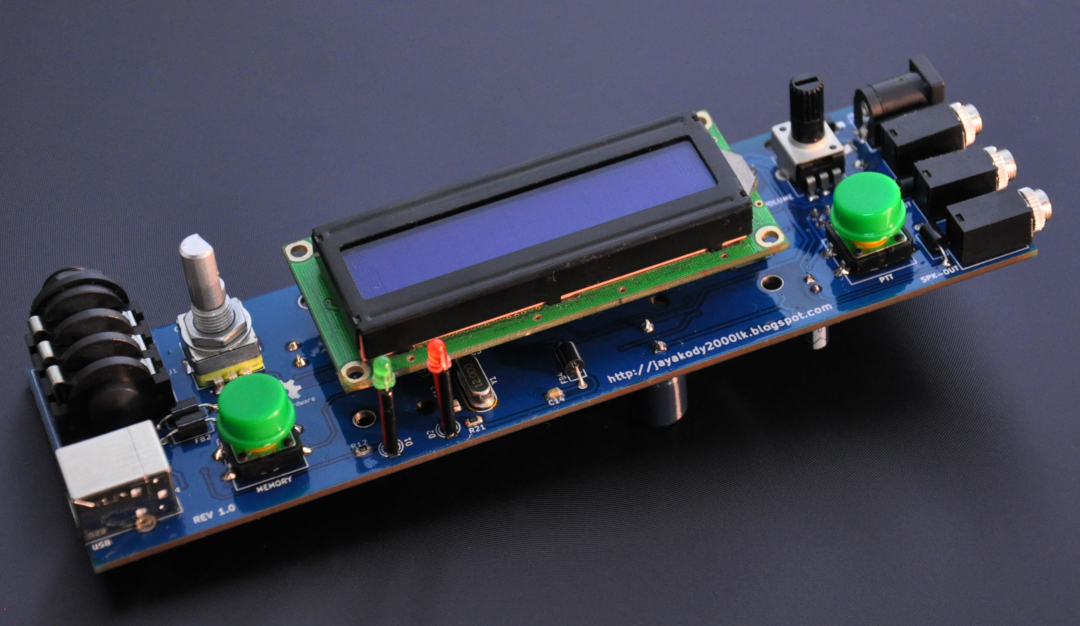
USB Morse Keyer is microcontroller based keyer with following features:
To reduce the dimension of the PCB this unit is designed with combining both through-hole and surface mount components. To facilitate future upgrades and modifications, the PIC16F886 MCU sticks with the standard 28-pin DIP package.
The USB interface of this unit is designed to work with most of the operating systems. It emulates a virtual serial terminal to transfer keystrokes to the keyer. In most of the operating systems, this interface works without installing any additional device drivers. To submit keystrokes user can use any serial terminal software such as PuTTY, Hyper Terminal, Minicom, etc.
This keyer is designed to work with 7V to 16V DC input voltage. The most recommended working voltage is 9V.
All the details related to this project are available at project documentation.
This is a certified open hardware project and all it's design files, firmware source codes, documentation, and other resource files are available at the project source repository. All the content of this project are distributed under the terms of the following license:
| Qty | Value | Footprint | References |
|---|---|---|---|
| 7 | 0.1MFD | Capacitor_SMD:C_0805_2012Metric | C1, C9, C10, C13, C14, C16, C20 |
| 6 | 10K | Resistor_SMD:R_0805_2012Metric | R2, R15, R16, R19, R20, R22 |
| 6 | EXCELSV35S | Inductor_THT:L_Axial_L6.6mm_D2.7mm_P10.16mm_Horizontal_Vishay_IM-2 | FB1, FB2, FB3, FB4, FB5, FB6 |
| 4 | 0.15MFD | Capacitor_SMD:C_0805_2012Metric | C4, C5, C6, C7 |
| 4 | 1.2K | Resistor_SMD:R_0805_2012Metric | R3, R4, R5, R6 |
| 4 | 100K | Resistor_SMD:R_0805_2012Metric | R9, R10, R13, R14 |
| 4 | 1K | Resistor_SMD:R_0805_2012Metric | R1, R7, R12, R17 |
| 4 | MountingHole_3.2mm_M3_ISO14580 | MountingHole:MountingHole_3.2mm_M3_ISO14580 | , , , |
| 3 | FC68102 | usb-morse-keyer:3.5mm-Jack-Socket-Mono | J2, J4, J6 |
| 3 | J3Y | Package_TO_SOT_SMD:SOT-23 | Q1, Q2, Q3 |
| 2 | 0.068MFD | Capacitor_SMD:C_0805_2012Metric | C2, C3 |
| 2 | 22pF | Capacitor_SMD:C_0805_2012Metric | C11, C12 |
| 2 | SMAJ6.0CA | Diode_SMD:D_SMA_Handsoldering | D4, D5 |
| 1 | 0.22MFD | Capacitor_SMD:C_0805_2012Metric | C19 |
| 1 | 0.47MFD | Capacitor_SMD:C_0805_2012Metric | C15 |
| 1 | 10MFD | Capacitor_THT:CP_Radial_D6.3mm_P2.50mm | C21 |
| 1 | 12.00MHz | Crystal:Crystal_HC49-U_Vertical | Y1 |
| 1 | 1MFD | Capacitor_THT:CP_Radial_D6.3mm_P2.50mm | C8 |
| 1 | 2.2K | Resistor_SMD:R_0805_2012Metric | R11 |
| 1 | 20K | Potentiometer_THT:Potentiometer_ACP_CA9-H3,8_Horizontal | RV2 |
| 1 | 220MFD | Capacitor_THT:CP_Radial_D10.0mm_P5.00mm | C17 |
| 1 | 22K | Resistor_SMD:R_0805_2012Metric | R8 |
| 1 | 3mm LED (GREEN) | LED_THT:LED_D3.0mm | D1 |
| 1 | 3mm LED (RED) | LED_THT:LED_D3.0mm | D2 |
| 1 | 4.7K | Resistor_SMD:R_0805_2012Metric | R21 |
| 1 | 470MFD | Capacitor_THT:CP_Radial_D12.5mm_P5.00mm | C18 |
| 1 | 560R | Resistor_SMD:R_0805_2012Metric | R18 |
| 1 | B20K | Potentiometer_THT:Potentiometer_Alpha_RD901F-40-00D_Single_Vertical | RV1 |
| 1 | BCP56 | Package_TO_SOT_SMD:SOT-223 | Q4 |
| 1 | CH340G | Package_SO:SOIC-16_3.9x9.9mm_P1.27mm | U3 |
| 1 | DC-IN | Connector_BarrelJack:BarrelJack_Horizontal | J8 |
| 1 | EC11 | Rotary_Encoder:RotaryEncoder_Alps_EC11E-Switch_Vertical_H20mm | SW1 |
| 1 | L78M05 | Package_TO_SOT_SMD:TO-252-2 | U4 |
| 1 | LCD-1602 | usb-morse-keyer:1602-LCD-Module | J5 |
| 1 | LM324 | Package_SO:SOIC-14_3.9x8.7mm_P1.27mm | U2 |
| 1 | MC32596 | Connector_USB:USB_B_OST_USB-B1HSxx_Horizontal | J3 |
| 1 | MEM-MAN | Button_Switch_THT:SW_PUSH-12mm | SW3 |
| 1 | PIC16F886IP | Package_DIP:DIP-28_W7.62mm_Socket_LongPads | U1 |
| 1 | PSG02952 | usb-morse-keyer:6.35mm-Jack-Socket-Stereo | J1 |
| 1 | PTT | Button_Switch_THT:SW_PUSH-12mm | SW2 |
| 1 | PTT-EXT | Connector_PinHeader_2.54mm:PinHeader_2x04_P2.54mm_Vertical | J7 |
| 1 | RESET | Button_Switch_THT:SW_PUSH_6mm | SW4 |
| 1 | SPK-8R | Connector_PinHeader_2.54mm:PinHeader_1x02_P2.54mm_Vertical | J9 |
| 1 | SS14 | Diode_SMD:D_SMA_Handsoldering | D3 |
| 1 | TDA7052A | Package_SO:SOIC-8_3.9x4.9mm_P1.27mm | U5 |
The 83 most common of 84 parts.

soggybag/Mutant-SMD
A redesign of the Mutant generative synth (MeeBleeps, https://github.com/Meebleeps/MeeBleeps-Mutant-Synth), based on the Eurorack version in /Documents/Arduino/projects/MutantGenerativeArduinoSynth/ (Instructables…

ControlSystemIntegrators/Therm_temp_4_20_xmtr
Fully analog 2-wire 4-20 mA NTC thermistor temperature transmitter, built from multi-sourced parts — plus an instrumentation-theory tutorial. Default build: 20-40 C for chocolate temperature control.


cjheath/jlcbasic
JLC Basic parts library for Kicad fetched and converted from EasyEDA

filliformes/pandore
pandore is an open-source digital audio instrument protyping platform based on the LattePanda Mu.


Benjamin-girard-1/geophys_acquisition_module
Modular ESP32-S3 geophysical data-acquisition system with custom hardware, multi-channel ADC, GNSS, IMU, removable analog sensor cards, firmware, and host tools
It measures 169.4 × 48.8 mm and has 2 copper layers, 1.6 mm thick.
84 parts, built around the CH340G, LM324, L78M05CV and SMAJ6.0CA. The full list of its parts is on this page, with links to each part's symbol and footprint where PCBKit's library has them.
From the dilshan/usb-morse-keyer repository on GitHub, at the commit this page was made from: the board is design/usb-morse-keyer.kicad_pcb. PCBKit opens the board in the browser, with nothing to install.
Its repository publishes it under the MIT licence: you may reuse it on that licence's terms (keep the author's notice, and for a copyleft licence share your changes alike).