2 layers102 × 37 mm

 orlopau/coffee-scale11
Scale for espresso and filter coffee.
Controller is an open-source printed circuit board by orlopau, from the orlopau/coffee-scale repository on GitHub. It is a 2-layer board of 68 × 81.5 mm with 55 parts on 61 nets, routed with 341 tracks and 54 vias.
It is built around the ESP32-WROOM-32, HX711 and AP2112K-3.3, with the IRLML2502, IRLML6402 and MMBT4403 among its other parts. Its parts include 15 capacitors, 15 resistors, 6 connectors, 5 ICs and 4 transistors. It belongs with the ESP32 boards of this library.


This project contains the schematics, code and 3D models for a coffee scale based on an ESP32.
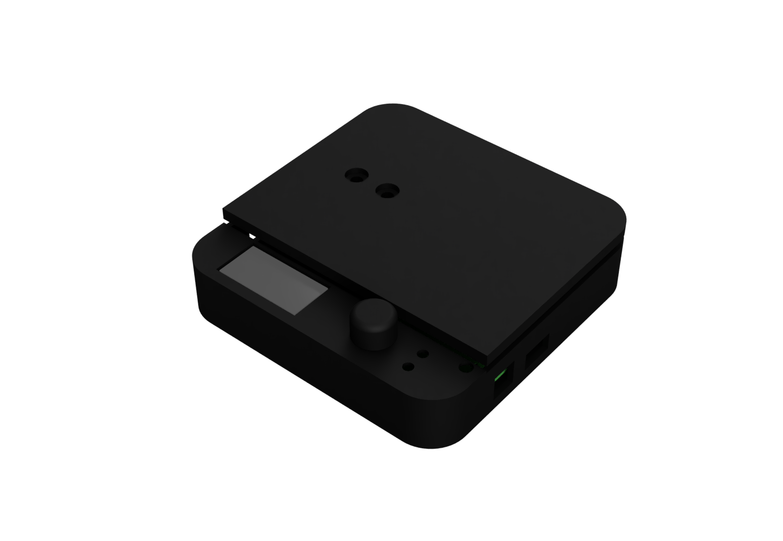
The scale can be used to brew coffee using a step-by-step recipe. The recipe is stored on the scale, and can be adjusted while brewing.
Possible adjustments include:
Once Wi-Fi is set up, the scale looks for a new firmware by itself every few starts, in the background while you weigh. When it finds one, it asks "Update to v1.10?" the next time you switch it on. Yes installs it and restarts, Later asks again next time. If a new firmware doesn't start properly, the scale goes back to the one before, says so, and doesn't offer that version again.
To update by hand, hold the button while switching on the scale and choose a language.
During development, the scale can install a build straight from your computer over Wi-Fi, without USB and without a GitHub release.
code/, run pio run -t serve. This builds the firmware and serves it on your network. It is found by the scale via mDNS, so your computer's IP does not matter. The first run installs the Python package zeroconf.The server keeps running, so for the next build repeat steps 2 and 3 (pio run -t serve rebuilds when restarted). If the scale already runs the served build, it shows "No update available". Your computer and the scale must be on the same network, and the firewall must allow incoming connections for the server.
The scale's automatic updates read GitHub's releases. To try them without publishing one, the dev server can pose as a release, and a build can claim to be an older version.
FIRMWARE_VERSION=v1.8.0 pio run -t upload. The scale then sees the latest release as newer.python scripts/dev_server.py .pio/build/esp32dev/firmware.bin --release v9.9.9 --port 8000 in code/. It prints the RELEASES_URL to build the scale with, e.g. RELEASES_URL=http://192.168.1.20:8000/releases pio run -t upload. Build the firmware to serve with the same RELEASES_URL, so it keeps asking your computer. The served build reports the last tag as its version, not --release, so after installing it the scale still finds v9.9.9 at every check; build it with FIRMWARE_VERSION=v9.9.9 too to see the scale stay quiet once it's up to date.A check runs at the first start of a new firmware if Wi-Fi is set up, then every 5th start; the serial log (AUTO_UPDATE) says when.
The scale can record the raw readings of its load cell, e.g. of taps or an espresso shot, and save them in its flash. The recordings are test data: native tests replay them with RecordedScale (code/src/native/recorded_scale.h). You don't need your computer while recording.
Click to start a recording. While recording, the scale shows the weight, the recording time, the time left and the number of markers. Click again to set a marker, e.g. when the pump starts. Turn the knob to tare the shown weight, e.g. after putting the cup on; while recording, the tare is saved in the recording too. Long-press to save the recording in the scale's flash; the scale then waits for the click that starts the next one. A recording takes at most 5 minutes, then the scale waits for the long-press. About 50 recordings fit. If saving fails, the recording is kept and the next long-press tries again. A recording that wasn't saved is lost when the scale is switched off.
To get the recordings to your computer, run pio run -t record in code/. It does not build anything, it waits for recordings. Only one of serve and record can run at a time. Open the recorder as above; the scale now finds the server and no longer says "No server". Long-press while idle to send all saved recordings, oldest first. Each one is deleted from the scale after it arrived, so if sending fails, the rest stays and the next long-press tries again.
The computer saves each recording as code/test/recordings/<date>_<time>.csv. Give the useful ones a name that says what they show, commit them, and delete the rest. A recording looks like this, with ms counted from its start on the scale's clock:
# coffee-scale recording
# firmware: v1.9.0
# grams_per_count: 0.002381
ms,event,value
0,sample,84012
101,sample,84020
1234,click,
1500,tare,
grams_per_count is the calibration of the scale that recorded, so tests can convert the raw readings to grams. A sample's value is the HX711's raw reading, signed. The samples stay raw after a tare, a tare row only says when it happened (RecordedScale::tares()). Firmware up to v1.9.0 recorded it unsigned (16540413 instead of -236803), and the replay converts those.
The emulator runs the firmware on your computer, in a window that shows the scale's display. It needs SDL2 (sudo apt install libsdl2-dev on Debian/Ubuntu).
cd code
pio run -e emulator -t exec
With COMPILE_LANG=de in front, it runs in German. The load cell is simulated, and the keyboard replaces the encoder:
| Key | Action |
|---|---|
| Left / Right | turn the encoder |
| Enter, Space | press the encoder, hold for a long press |
| Up / Down | put 1 g on the scale or take it off, with Shift 0.1 g |
| PageUp / PageDown | 10 g on or off |
| Home | 100 g, e.g. for the calibration |
| 0, Backspace | clear the scale |
| F | pour on/off, 2 g/s |
| S | espresso shot: 6 s pre-infusion, then about 38 g in 33 s |
| L | lift the platform for a moment (lift-to-tare) |
| N | noise on/off |
| - / + | slower/faster time, up to 20x (1x while the button is held) |
| P | save a screenshot to the current directory |
| Esc, Q | quit |
The window title shows the weight on the scale. The frame around the display lights up while the buzzer sounds. Settings are kept in memory only, and the boot splash screen and the updater only run on the device.
The native tests render every screen through u8g2, set up like the scale's display, and compare it with the reference images in code/test/native/test_screenshots/screens/. A screen that changes fails the tests, and its new image is written to code/test/native/test_screenshots/failed/ (on GitHub, attached to the CI run as failed-screenshots).
After changing a screen on purpose, accept the new images and commit them with the change:
cd code
UPDATE_SCREENSHOTS=1 pio test -e native -f native/test_screenshots
The diff of the pull request then shows each changed screen before and after.
| Qty | Value | Footprint | References |
|---|---|---|---|
| 7 | 0.1uF | Capacitor_SMD:C_0603_1608Metric_Pad1.08x0.95mm_HandSolder | C1, C4, C6, C7, C9, C14, C15 |
| 4 | 10uF | Capacitor_SMD:C_1206_3216Metric | C2, C3, C5, C8 |
| 3 | 100 | Resistor_SMD:R_0603_1608Metric_Pad0.98x0.95mm_HandSolder | R3, R4, R5 |
| 3 | 10k | Resistor_SMD:R_0603_1608Metric_Pad0.98x0.95mm_HandSolder | R1, R2, R6 |
| 3 | 47k | Resistor_SMD:R_0603_1608Metric_Pad0.98x0.95mm_HandSolder | R10, R11, R12 |
| 2 | 1uF | Capacitor_SMD:C_0805_2012Metric | C12, C13 |
| 2 | 4.7uF | Capacitor_SMD:C_0805_2012Metric | C10, C11 |
| 2 | 5.1k | Resistor_SMD:R_0603_1608Metric_Pad0.98x0.95mm_HandSolder | R13, R14 |
| 2 | IRLML2502 | Package_TO_SOT_SMD:SOT-23 | Q3, Q4 |
| 2 | MountingHoleLoadcell | MountingHole:MountingHole_5.3mm_M5_ISO7380 | H1, H2 |
| 1 | 130 | Resistor_SMD:R_0603_1608Metric_Pad0.98x0.95mm_HandSolder | R9 |
| 1 | 1N5819 | Diode_SMD:D_SMA_Handsoldering | D2 |
| 1 | 1k | Resistor_SMD:R_0603_1608Metric_Pad0.98x0.95mm_HandSolder | R15 |
| 1 | 2k | Resistor_SMD:R_0603_1608Metric_Pad0.98x0.95mm_HandSolder | R8 |
| 1 | 8.2k | Resistor_SMD:R_0603_1608Metric_Pad0.98x0.95mm_HandSolder | R7 |
| 1 | AP2112K-3.3 | Package_TO_SOT_SMD:SOT-23-5 | U4 |
| 1 | Buzzer | Buzzer_Beeper:Buzzer_12x9.5RM7.6 | BZ1 |
| 1 | Conn_Display | Connector_Wire:SolderWire-0.5sqmm_1x04_P4.8mm_D0.9mm_OD2.3mm | J2 |
| 1 | Conn_G13 | Connector_Wire:SolderWire-0.5sqmm_1x02_P4.8mm_D0.9mm_OD2.3mm | J5 |
| 1 | Conn_LiPo | Connector_Wire:SolderWire-0.5sqmm_1x02_P4.8mm_D0.9mm_OD2.3mm | J4 |
| 1 | Conn_LoadCell | Connector_Wire:SolderWire-0.5sqmm_1x05_P4.8mm_D0.9mm_OD2.3mm | J1 |
| 1 | Conn_UART | Connector_PinHeader_2.54mm:PinHeader_1x03_P2.54mm_Horizontal | J3 |
| 1 | DW01-P | Package_TO_SOT_SMD:SOT-23-6_Handsoldering | U5 |
| 1 | ESP32-WROOM-32 | RF_Module:ESP32-WROOM-32 | U1 |
| 1 | HX711 | Package_SO:SOP-16_3.9x9.9mm_P1.27mm | U2 |
| 1 | IRLML6402 | Package_TO_SOT_SMD:SOT-23 | Q2 |
| 1 | LED | LED_SMD:LED_1206_3216Metric | D1 |
| 1 | MCP73831-2-OT | Package_TO_SOT_SMD:SOT-23-5 | U3 |
| 1 | MMBT4403 | Package_TO_SOT_SMD:SOT-23 | Q1 |
| 1 | RotaryEncoder_Switch | Rotary_Encoder:RotaryEncoder_Alps_EC11E-Switch_Vertical_H20mm | SW3 |
| 1 | SMAJ6.0CA | Diode_SMD:D_SMA | D3 |
| 1 | SW_Boot | Button_Switch_THT:SW_PUSH_6mm_H5mm | SW2 |
| 1 | SW_EN | Button_Switch_THT:SW_PUSH_6mm_H5mm | SW1 |
| 1 | SW_Power | Connector_Wire:SolderWire-0.5sqmm_1x02_P4.8mm_D0.9mm_OD2.3mm | SW4 |
| 1 | USB-C-6Pin | Custom:USB_C_6Pin | P1 |


FilMarini/bigbanger
An ESP32-based Bluetooth-enabled scaling device for climbing training,compliant with the Tindeq Progressor API, with firmware available in Micropython or Rust.

SolderedElectronics/Load-cell-ampfilier-HX711-board-hardware-design
Hardware design, BOM, gerbers and 3D files for Load-cell-ampfilier-HX711-board designed by Soldered Electronics.

jvasilakes/mito
A tiny, cheap, hackable, completely open-source force gauge for isometric finger strength training.

EcoApi/EcoApi_BeeHiveMonitoring
describ options with 0R resistors. etc ...

callumsnowden/aero21412_test_rig
AERO21412 Avionics Coursework 1 – Wind Tunnel Test Rig "Black Box"

jmajew/thrust_tool
DIY tool for measurements of thrust, torque, etc., of an electric motor with propeller
It measures 68 × 81.5 mm and has 2 copper layers, 1.6 mm thick.
55 parts, built around the ESP32-WROOM-32, HX711, AP2112K-3.3 and IRLML2502. The full list of its parts is on this page, with links to each part's symbol and footprint where PCBKit's library has them.
From the orlopau/coffee-scale repository on GitHub, at the commit this page was made from: the board is schematics/controller.kicad_pcb and its schematic schematics/controller.kicad_sch. PCBKit opens the board in the browser, with nothing to install.
Its repository states no licence, so its author keeps all rights: ask orlopau before reusing the design.