2 layers78 × 54 mm

 dilshan/electronic-limit-switch1
Automatic fluid level control module
Electronic limit sw is an open-source printed circuit board by dilshan, from the dilshan/electronic-limit-switch repository on GitHub, published under the MIT licence. It is a 2-layer board of 98 × 36.2 mm with 33 parts on 20 nets, routed with 210 tracks and 9 vias.
It is built around the HLK-2M05, ZMM5V6 and 10D561K, with the MMBT2222 and SMBJ6.0A among its other parts. Its parts include 7 diodes, 6 resistors, 5 capacitors, 4 connectors and 1 IC. It belongs with the robots and motor control boards and the PIC boards of this library.


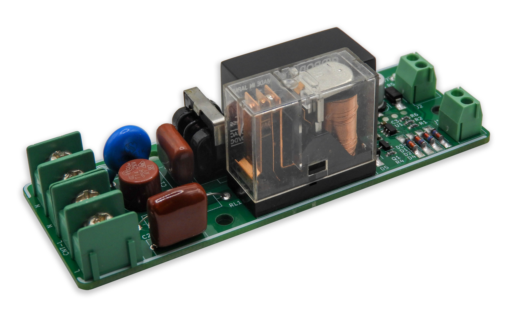
This is an open-source fluid level control module designed for reliable and automated liquid management in tanks.
This module can utilize two float-type limit switches or electronic sensor switches to detect fluid levels and control a relay accordingly. A microcontroller implements hysteresis logic to avoid unnecessary relay toggling caused by minor fluid level fluctuations, which enhances the system's reliability and lifespan.
The module monitors two limit switches:
Based on these inputs, the onboard microcontroller:
The J4 terminal block provides:
This is a certified open-source hardware project. All design files, documentation, and firmware source code are available for download at the project source repository. The content of this project is distributed under the following licenses:

| Qty | Value | Footprint | References |
|---|---|---|---|
| 4 | M3 | MountingHole:MountingHole_3.5mm | H1, H2, H3, H4 |
| 4 | ZMM5V6 | Diode_SMD:D_MiniMELF_Handsoldering | D1, D2, D3, D4 |
| 3 | 1K | Resistor_SMD:R_0603_1608Metric_Pad0.98x0.95mm_HandSolder | R1, R2, R5 |
| 2 | 10K | Resistor_SMD:R_0603_1608Metric_Pad0.98x0.95mm_HandSolder | R4, R6 |
| 2 | 3.5mm - 2-pin screw terminal | Connector_Phoenix_MC:PhoenixContact_MCV_1,5_2-G-3.5_1x02_P3.50mm_Vertical | J1, J2 |
| 1 | 0.1MFD | Capacitor_THT:C_Rect_L11.0mm_W4.3mm_P10.00mm_MKT | C1 |
| 1 | 0.1MFD | Capacitor_SMD:C_0603_1608Metric_Pad1.08x0.95mm_HandSolder | C3 |
| 1 | 0.22MFD | Capacitor_THT:C_Rect_L11.0mm_W5.1mm_P10.00mm_MKT | C2 |
| 1 | 0.5A | Fuse:Fuse_Littelfuse_372_D8.50mm | F1 |
| 1 | 10D561 | Varistor:RV_Disc_D12mm_W4.2mm_P7.5mm | TH1 |
| 1 | 10MFD | Capacitor_SMD:C_0805_2012Metric_Pad1.18x1.45mm_HandSolder | C4 |
| 1 | 10mH | elect-footprints:CM-Choke-15.5mmx10.9mm | FL1 |
| 1 | 120R / 2W | Resistor_THT:R_Axial_DIN0516_L15.5mm_D5.0mm_P20.32mm_Horizontal | R3 |
| 1 | 330MFD | Capacitor_SMD:CP_Elec_6.3x7.7 | C5 |
| 1 | 7.62mm - 4-pin screw terminal | elect-footprints:Screw-Terminal-4Way-7.62mm | J4 |
| 1 | G2RL-2-DC5 | Relay_THT:Relay_DPDT_Omron_G2RL | RL1 |
| 1 | HLK-2M05 | elect-footprints:PSU-Module-10.5mmx16.5mm | PS1 |
| 1 | M1 | Diode_SMD:D_SMA_Handsoldering | D5 |
| 1 | MMBT2222 | Package_TO_SOT_SMD:SOT-23-3 | Q1 |
| 1 | PIC10F200-IOT | Package_TO_SOT_SMD:SOT-23-6 | U1 |
| 1 | RED 0805 | LED_SMD:LED_0805_2012Metric_Pad1.15x1.40mm_HandSolder | D7 |
| 1 | SMBJ6.0A | Diode_SMD:D_SMB_Handsoldering | D6 |
| 1 | SMD - 2.54mm 4-pin pad terminal | elect-footprints:pogo-2.54mmx4 | J3 |
It measures 98 × 36.2 mm and has 2 copper layers, 1.6 mm thick.
33 parts, built around the HLK-2M05, ZMM5V6, 10D561K and MMBT2222. The full list of its parts is on this page, with links to each part's symbol and footprint where PCBKit's library has them.
From the dilshan/electronic-limit-switch repository on GitHub, at the commit this page was made from: the board is design/electronic-limit-sw.kicad_pcb and its schematic design/electronic-limit-sw.kicad_sch. PCBKit opens the board in the browser, with nothing to install.
Its repository publishes it under the MIT licence: you may reuse it on that licence's terms (keep the author's notice, and for a copyleft licence share your changes alike).


amonbenson/laserharp
Setup a virtual environment and install the dependencies:

MURPHYENGINEERING/STM32F405RGT6-Breakout
Following along with Phil's Lab: https://www.youtube.com/watch?v=t5phi3nT8OU

Will946/TeaCupHotPlate
Keeps your tea at temperature by turning the circuit board itself into the heating element. Overengineered, like all good tea rituals.