2 layers93 × 173 mm
Batch 1
CDFER/Business-Cards
Showcasing a collection of functional PCB business cards, each demonstrating a unique embedded electronics project.
479 parts9

 Will946/TeaCupHotPlate1
Keeps your tea at temperature by turning the circuit board itself into the heating element. Overengineered, like all good tea rituals.
Tea Cozy Hotplate is an open-source printed circuit board by Will946, from the Will946/TeaCupHotPlate repository on GitHub, published under the MIT licence. It is a 2-layer board of 93 × 57 mm with 140 parts on 89 nets, routed with 1,162 tracks and 128 vias.
It is built around the SM4007PL, 0402 ±5% 1K6 and 1N5819WS, with the SRV05 and ZMM5V6 among its other parts. Its parts include 36 capacitors, 33 resistors, 10 diodes, 5 ICs and 3 connectors. It belongs with the STM32 boards of this library.


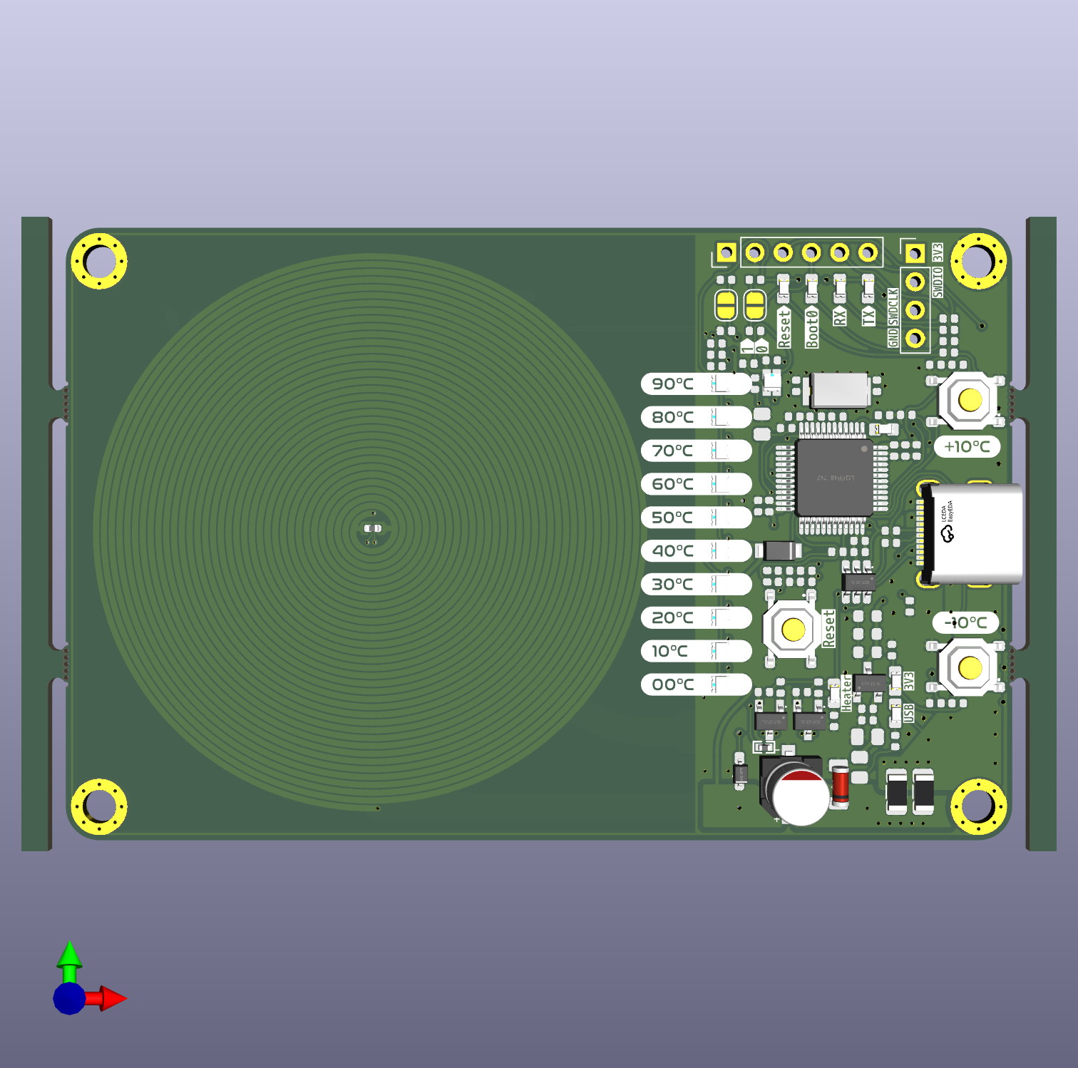
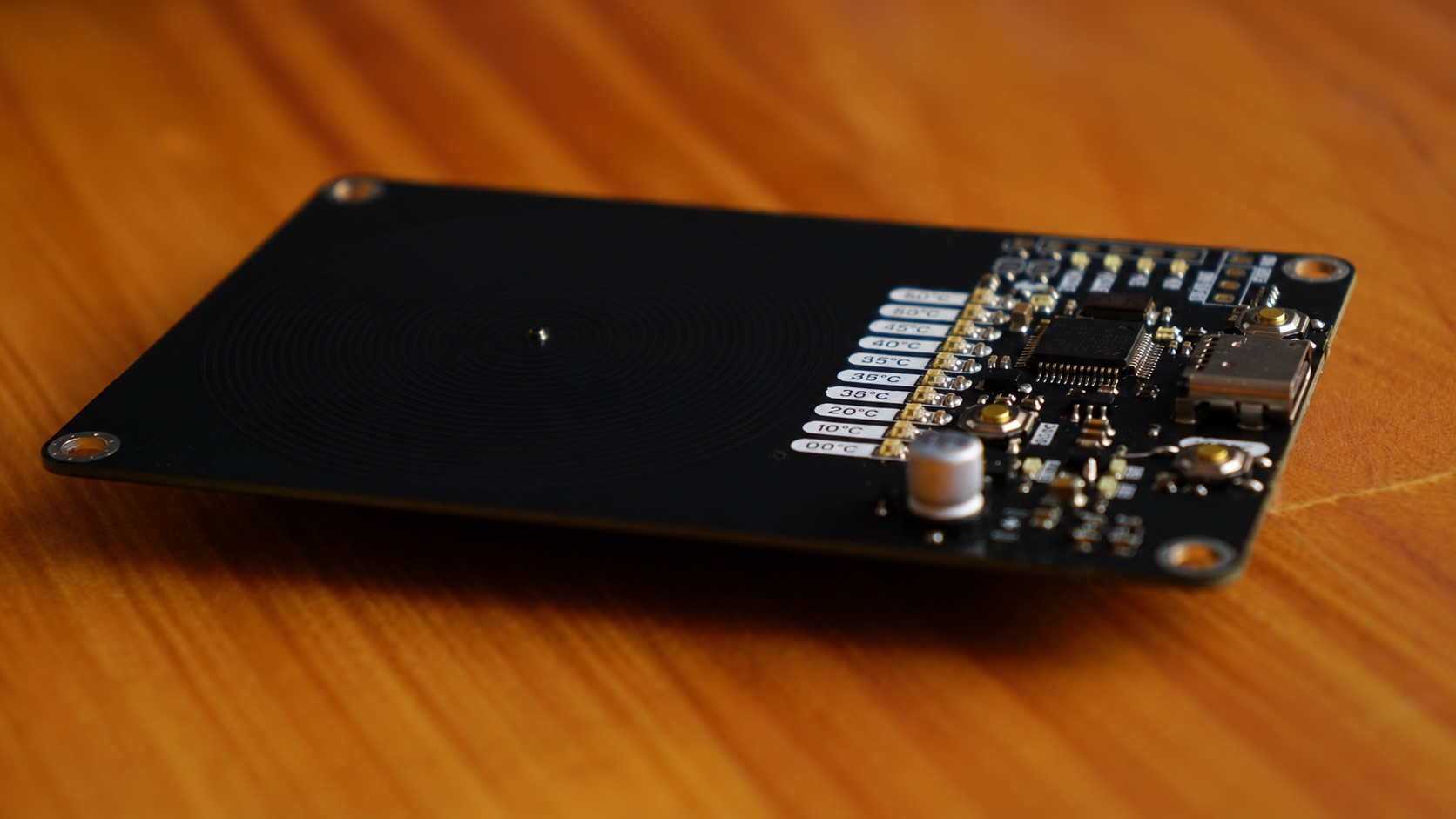
The Tea Cozy Hotplate is a USB-C powered, closed-loop temperature-controlled hotplate sized to sit under a single cup of tea. An STM32F103C8T6 ("Blue Pill" class MCU) reads a thermistor bonded to the underside of the heating coil, PWM drives two low-side NMOS switches to regulate power into a spiral PCB heater trace, and reports the current setpoint on a ten segment WS2812B ("Neopixel") LED bar that doubles as a 0 to 90 degrees C temperature dial. Two buttons let you nudge the setpoint up or down in 10 degree steps, and the whole board is bus powered off a single USB-C cable, with no separate power brick required.
Power in. 5V arrives on the USB-C receptacle (J2), passes through a pair of 1.5A resettable (PTC) fuses on VBUS, and is clamped by an SRV05 ESD protection array on D+/D- and the CC lines. A single 2.2 ohm sense resistor pair plus 5.1kΩ pull downs on CC1/CC2 tell the upstream USB-C source the board is a fixed 5V/1.4A(ish) legacy sink. There is no PD negotiation chip, just resistor based CC termination, so any 5V USB-C source works. A XC6206P332MR LDO steps 5V down to a clean 3.3V rail for the MCU, LEDs, and sensors. A Zener (D2, ZMM5V6) sits across VBUS as extra transient protection.
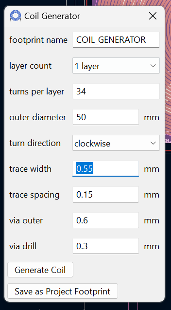
The heater. The "hotplate" itself is not a separate component, it is a spiral trace etched directly into the PCB copper, measuring roughly 3.75 ohms in the assembled board, generated in KiCad with its built in Coil Generator tool (see the JLCPCB Heater Coil section below for the exact settings and trace math). Two AO3400A N-channel MOSFETs (U3/U4) sit low side between the coil and ground, each gated through a 4.7kΩ series resistor off the MCU's Hotplate_EN PWM line (rated for up to about 33kHz switching per the schematic notes). A flyback diode (D1, 1N5819WS Schottky) protects the switches from inductive kickback. The STM32 runs a PWM duty cycle proportional to the error between the setpoint and the measured coil temperature, essentially a bang bang or PID control loop over a resistive heater, similar to a soldering iron controller.
Temperature sensing. Two 47kΩ NTC thermistors are read as simple resistor divider ADC inputs. One (Temp_Coil) is thermally bonded near the heating coil to close the control loop, and a second (Temp_Mosfet) monitors the driver FETs so firmware can back off PWM if the switches themselves start overheating, giving thermal protection headroom beyond just controlling cup temperature.
Display and setpoint. Ten WS2812B addressable RGB LEDs, one per 10 degree step from 0 to 90 degrees C, are chained off a single data line (Neopixel_Bus) driven directly by an MCU GPIO, with no separate LED driver IC needed. Two tactile buttons (SW2/SW3, "Up"/"Down" in the schematic) step the setpoint in 10 degree increments, and the firmware lights LEDs up to the current setpoint.
Programming and debug. The board exposes both an SWD header (SWDIO/SWDCLK/GND/3V3) for use with an ST-Link V2, and a separate serial header (MCU_TX/MCU_RX/Reset/BOOT0) with its own status LEDs, so firmware can be flashed over SWD or bootloaded over UART without opening a case. Dedicated Reset and BOOT0 push buttons plus solder jumpers (JP1/JP2) let you force the STM32 into its UART bootloader without needing to touch the board with tweezers.
MCU_TX/MCU_RX) using the BOOT0/Reset buttons or JP1/JP2 jumpers to force bootloader mode.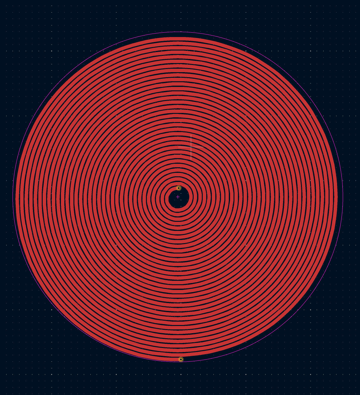
| Qty | Value | Footprint | References |
|---|---|---|---|
| 15 | 100nF | footprint:0402_1005Metric | C2, C4, C11, C16, C19, C20, C21, C22, C23, C24, C25, C26, C27, C28, C29 |
| 11 | XL-1615RGBC-WS2812B | footprint:LED-SMD_4P-L1.6-W1.5_XL-1615RGBC-WS2812B | RGB1, RGB2, RGB3, RGB4, RGB5, RGB6, RGB7, RGB8, RGB9, RGB10, RGB11 |
| 5 | 0603,Red | footprint:LED0603 | LED1, LED2, LED6, LED7, LED8 |
| 4 | clipboard:29b2475f-d1f9-413a-acd7-ed0fdfac1ce2 | , , , | |
| 4 | clipboard:74cc307d-ef1c-4d55-ab28-7a463adb6a10 | , , , | |
| 4 | 0402,1.2k | footprint:0402_1005Metric | R6, R15, R16, R22 |
| 4 | 0402,100k | footprint:0402_1005Metric | R8, R9, R19, R24 |
| 4 | 0402,1k | footprint:0402_1005Metric | R10, R11, R32, R33 |
| 4 | 330pF | footprint:0402_1005Metric | C9, C10, C15, C17 |
| 4 | MountingHole_3.2mm_M3 | MountingHole:MountingHole_3.2mm_M3 | M1, M2, M3, M4 |
| 3 | 0402,10k | footprint:0402_1005Metric | R5, R26, R27 |
| 3 | 0402,1uF,25V,X5R | footprint:0402_1005Metric | C5, C30, C31 |
| 3 | 0402,4.7k | footprint:0402_1005Metric | R4, R20, R21 |
| 3 | 0603,Yellow | footprint:LED0603 | LED3, LED4, LED5 |
| 3 | Button SPST 50mA 12V | footprint:SW-SMD_4P-L5.1-W5.1-P3.70-LS6.5-TL-2 | SW1, SW2, SW3 |
| 2 | 0402,100 | footprint:0402_1005Metric | R23, R25 |
| 2 | 0402,100nF,16V,X7R | footprint:0402_1005Metric | C34, C35 |
| 2 | 0402,20pF,50V,C0G | footprint:0402_1005Metric | C1, C6 |
| 2 | 0402,22 | footprint:0402_1005Metric | R2, R3 |
| 2 | 0402,4.7uF,10V,X5R | footprint:0402_1005Metric | C8, C18 |
| 2 | 0402,47k | footprint:0402_1005Metric | R30, R31 |
| 2 | 0402,5.1k | footprint:0402_1005Metric | R13, R14 |
| 2 | 0402,680 | footprint:0402_1005Metric | R12, R17 |
| 2 | 0603,470nF,25V,X7R | footprint:0603_1608Metric | C12, C14 |
| 2 | 1.5A Resettable Fuse | Fuse:Fuse_1206_3216Metric | F1, F2 |
| 2 | 47k 3950K | footprint:R0402 | R28, R29 |
| 2 | Jumper_2_Open | Jumper:SolderJumper-2_P1.3mm_Open_RoundedPad1.0x1.5mm | JP1, JP2 |
| 2 | NMOS AO3400A | footprint:SOT-23-3_L2.9-W1.6-P1.90-LS2.8-BR | U3, U4 |
| 1 | 0402,150 | footprint:0402_1005Metric | R7 |
| 1 | 0402,1M | footprint:0402_1005Metric | R1 |
| 1 | 0402,330 | footprint:0402_1005Metric | R18 |
| 1 | 0402,330pF,50V,C0G | footprint:0402_1005Metric | C7 |
| 1 | 0603,330pF,50V,C0G | footprint:0603_1608Metric | C13 |
| 1 | 0805,1uF,50V,X7R | footprint:0805_2012Metric | C3 |
| 1 | 0805,800mA | footprint:0805_2012Metric | FB1 |
| 1 | 10nF | footprint:0402_1005Metric | C32 |
| 1 | 1N5819WS | footprint:SOD-323_L1.8-W1.3-LS2.5-RD | D1 |
| 1 | 1uF | footprint:0805_2012Metric | C33 |
| 1 | 22uF 35V | footprint:CAP-SMD_BD5.0-L5.3-W5.3-LS6.0-FD | C60 |
| 1 | 8MHz 20pF ±10ppm | footprint:CRYSTAL-SMD_L5.0-W3.2 | U2 |
| 1 | Conn_01x04_Socket | Connector_PinHeader_2.54mm:PinHeader_1x04_P2.54mm_Vertical | J3 |
| 1 | Conn_01x06_Socket | Connector_PinHeader_2.54mm:PinHeader_1x06_P2.54mm_Vertical | J1 |
| 1 | G*** | kibuzzard-669770CC | kibuzzard-669770CC |
| 1 | G*** | kibuzzard-6697709F | kibuzzard-6697709F |
| 1 | G*** | kibuzzard-669770B6 | kibuzzard-669770B6 |
| 1 | G*** | kibuzzard-66977083 | kibuzzard-66977083 |
| 1 | G*** | kibuzzard-6697719B | kibuzzard-6697719B |
| 1 | G*** | kibuzzard-66977193 | kibuzzard-66977193 |
| 1 | G*** | kibuzzard-669770DC | kibuzzard-669770DC |
| 1 | G*** | kibuzzard-6697716D | kibuzzard-6697716D |
| 1 | G*** | kibuzzard-669771D1 | kibuzzard-669771D1 |
| 1 | G*** | kibuzzard-6697705A | kibuzzard-6697705A |
| 1 | G*** | kibuzzard-66977187 | kibuzzard-66977187 |
| 1 | G*** | kibuzzard-66977218 | kibuzzard-66977218 |
| 1 | G*** | kibuzzard-669771DB | kibuzzard-669771DB |
| 1 | G*** | kibuzzard-669770AA | kibuzzard-669770AA |
| 1 | Heater | extended_parts:heater_coil | HC1 |
| 1 | LDO 3.3V 200mA XC6206P332MR | footprint:SOT-23-3_L2.9-W1.6-P1.90-LS2.8-BR | LDO1 |
| 1 | LOGO | LOGO | G*** |
| 1 | MCU 72MHz STM32F103C8T6 | footprint:LQFP-48_L7.0-W7.0-P0.50-LS9.0-BL | U1 |
| 1 | SM4007PL | footprint:SOD-123F_L2.8-W1.8-LS3.7-RD | U5 |
| 1 | SRV05 | footprint:SOT-23-6_L2.9-W1.6-P0.95-LS2.8-BR | ESD1 |
| 1 | USB_C_Receptacle | extended_parts:TYPE-C-SMD_C9900025773 | J2 |
| 1 | ZMM5V6 | footprint:LL-34_L3.5-W1.5-RD | D2 |
The 136 most common of 140 parts.
It measures 93 × 57 mm and has 2 copper layers, 0.99 mm thick.
140 parts, built around the SM4007PL, 0402 ±5% 1K6, 1N5819WS and SRV05. The full list of its parts is on this page, with links to each part's symbol and footprint where PCBKit's library has them.
From the Will946/TeaCupHotPlate repository on GitHub, at the commit this page was made from: the board is PCB/Tea Cozy Hotplate.kicad_pcb and its schematic PCB/Tea Cozy Hotplate.kicad_sch. PCBKit opens the board in the browser, with nothing to install.
Its repository publishes it under the MIT licence: you may reuse it on that licence's terms (keep the author's notice, and for a copyleft licence share your changes alike).
CDFER/Business-Cards
Showcasing a collection of functional PCB business cards, each demonstrating a unique embedded electronics project.

wszeto9/ESP32-S3-HUB75-Driver
This board serves as the Matrix Display driver for MIT's 2.007 gameboards in Spring 2024 and Spring 2025. The board can take 4 button inputs, Stemma-QT I2C sensors, and breaks out 8 GPIO pins for future use.

klaus-liebler/sensact
Es gibt vier Namespaces für Nachrichten "REQUEST" und "RESPONSE", "EVENT" und "ACKNOWLEDGE". Dies wird mit den beiden LSB des Versions-Namespace-Bytes erklärt (Somit bleiben 64 Versionierungsmöglichkeiten) Alle vier…

jasonalexander-ja/PicoChain
Power and I2C daisy chained over ethernet patch cables.

spassigl/ATMega32A-demo-board
An ATMega32A breakout board with exposed GPIO pins, LEDs, tactile switches and a buzzer

ClemensElflein/xESC_YF_rev4-adapter
[![Contributors][contributors-shield]][contributors-url] [![Forks][forks-shield]][forks-url] [![Stargazers][stars-shield]][stars-url] [![Issues][issues-shield]][issues-url] [![MIT License][license-shield]][license-url]

