
2 layers30 × 85.5 mm
Power Deck Longitudinal v0.1
dgtaheno/RocketOS
ESP32 flight computer with MAVLink telemetry, QGroundControl integration, GPS, BMP388 altimetry, INA219 power monitoring and fault-tolerant SD logging
8 parts2MIT

 dgtaheno/RocketOS2
ESP32 flight computer with MAVLink telemetry, QGroundControl integration, GPS, BMP388 altimetry, INA219 power monitoring and fault-tolerant SD logging
Main Deck Longitudinal v0.1 is an open-source printed circuit board by dgtaheno, from the dgtaheno/RocketOS repository on GitHub, published under the MIT licence. It is a 2-layer board of 30 × 85.5 mm with 11 parts on 55 nets, routed with 285 tracks and 0 vias.
It is built around the NEO-M9N-00B, BMP388 and S8050. Its parts include 6 connectors, 2 resistors, 2 ICs and 1 transistor. It belongs with the sensors and measurement and radio and wireless boards and the ESP32 boards of this library.


Open-source ESP32-S3 flight computer, telemetry, data-logging and validation platform for experimental model rockets.
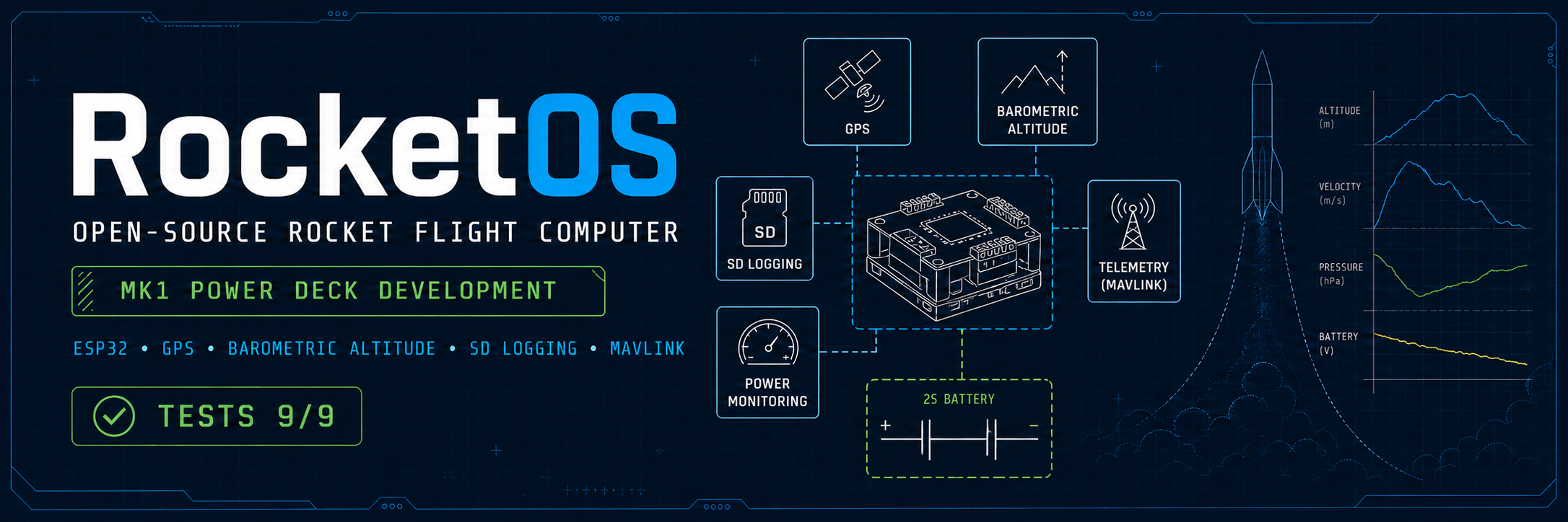









RocketOS is currently at the Mk1 prototype integration stage.
The project has progressed from an ESP32 DevKitC development prototype to an ESP32-S3 N16R8 Mk1 architecture with two longitudinal prototype PCBs:
Both PCB designs have been released for prototype fabrication.
The current ESP32-S3 firmware builds successfully and the native regression suite passes 9/9 tests.
The Mk1 electrical configuration is now being reproduced and validated on the bench before physical PCB bring-up.
Bench validation has confirmed simultaneous shared-I2C operation of:
0x40.0x68.0x76.0x77.The external BMP388 address was changed from its default 0x77 to 0x76 to resolve the address collision with the BMP180 present on the GY-87.
The fabricated Mk1 PCBs have not yet been physically brought up or flight validated.
RocketOS currently provides:
The target Mk1 ecosystem additionally includes:
These target functions are not all implemented yet.
The Main Deck is based on the ESP32-S3 N16R8 and provides interfaces for:
| Component | Model | Function |
|---|---|---|
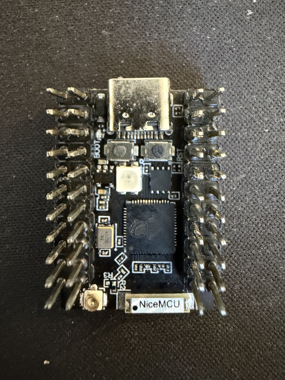
| Microcontroller | ESP32-S3 N16R8 | Flight computer |
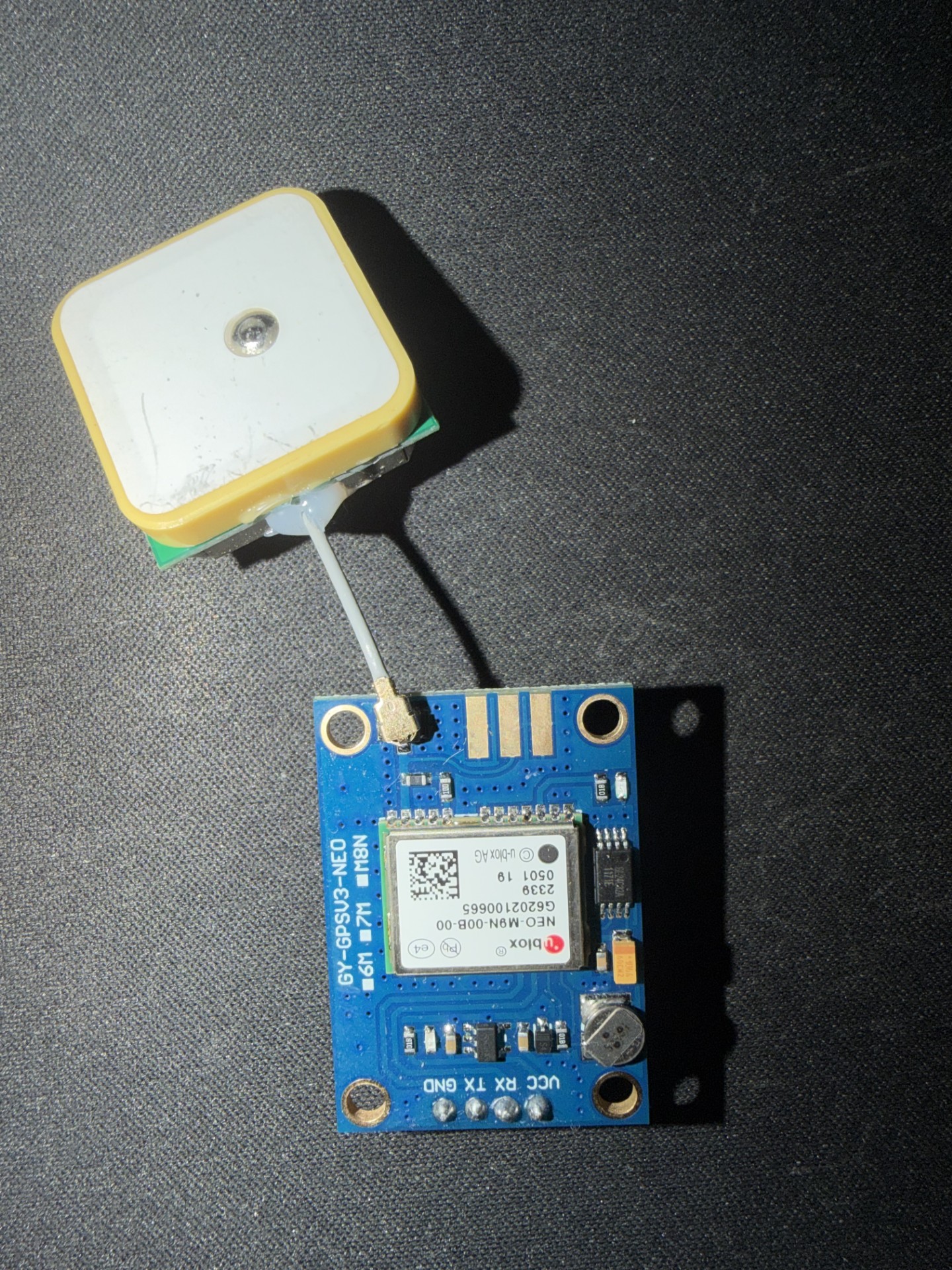
| GNSS | u-blox NEO-M9N | Position, altitude, speed and UTC |
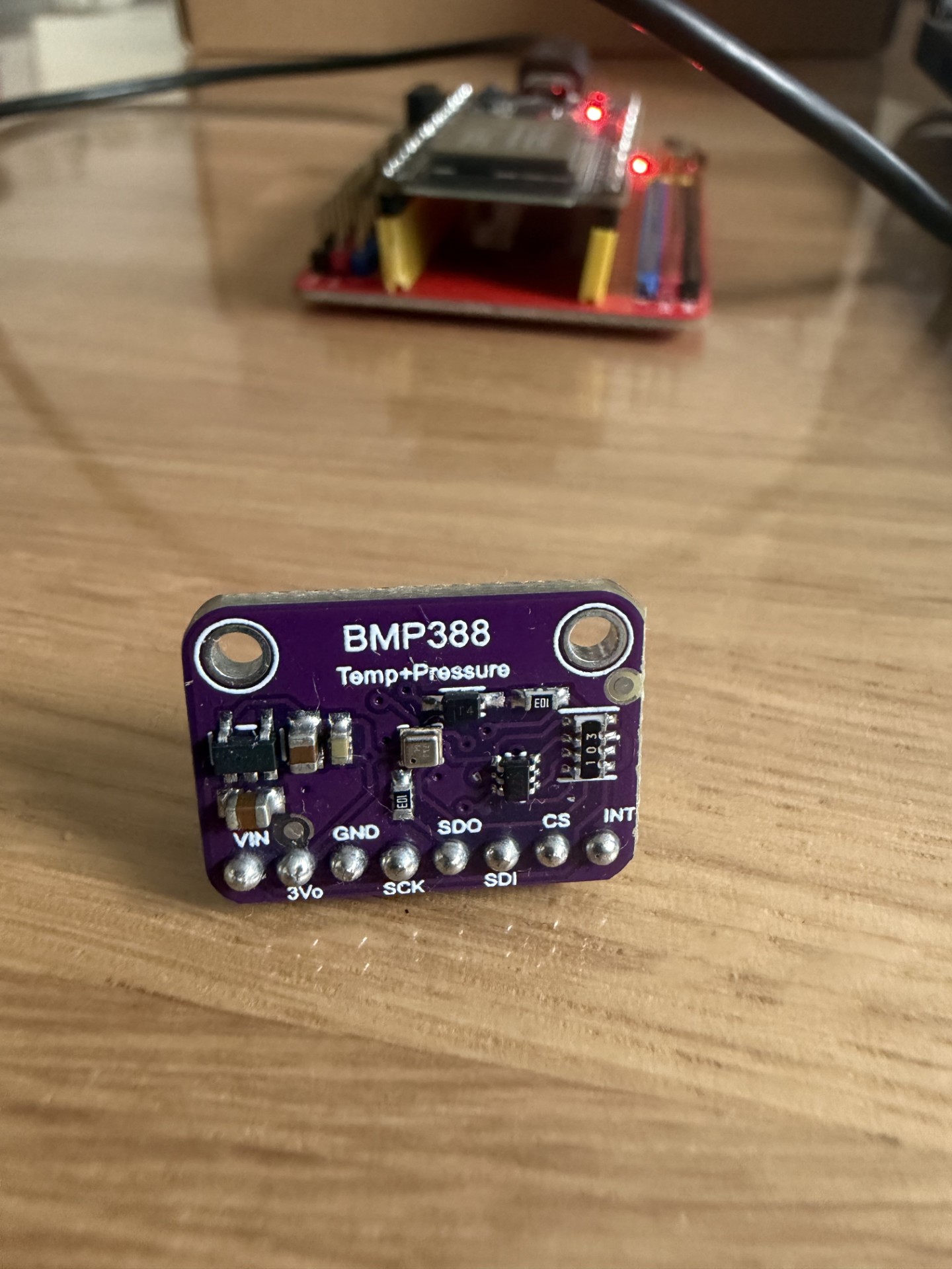
| Barometer | BMP388 at I2C 0x76 | Pressure, temperature and altitude |
| Storage | MicroSD | Flight-data logging |
| IMU module | GY-87 | Future inertial sensing |
| Radio | Ai-Thinker Ra-02 / SX1278 | Future LoRa telemetry |
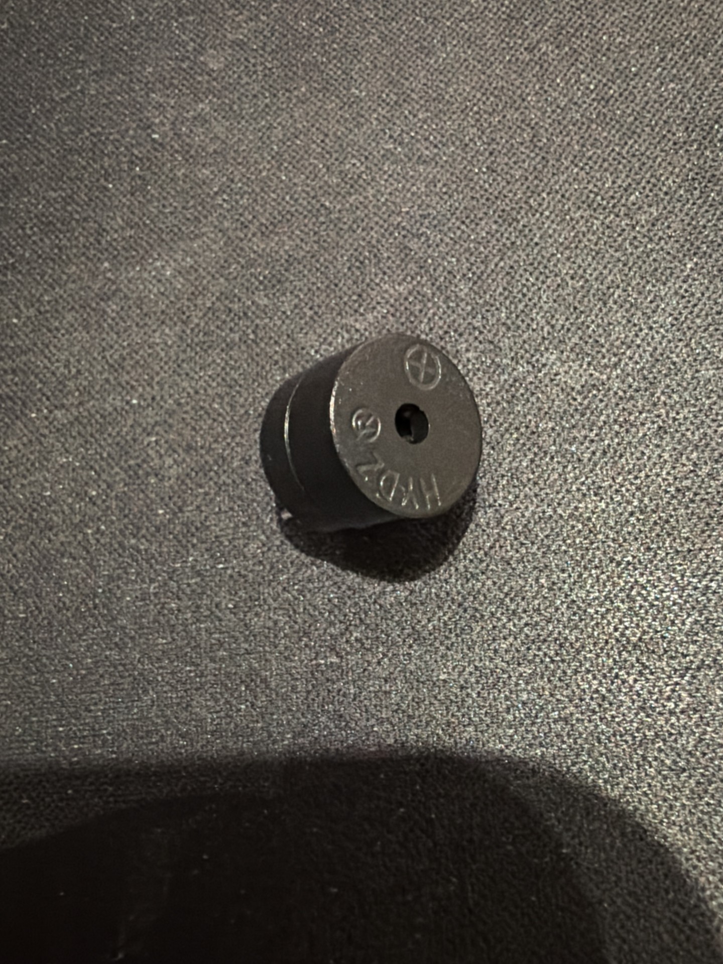
| Audible feedback | Active buzzer | Status and recovery beacon |
The external BMP388 is fixed at I2C address 0x76 by tying SDO to GND. This avoids the 0x77 address used by the BMP180 present on the Mk1 GY-87 module.
The already-released Main Deck v0.1 fabrication package predates this correction and leaves BMP388 SDO unconnected. Fabricated v0.1 boards therefore require an SDO-to-GND rework during assembly. The current KiCad source includes the corrected connection.
Main Deck envelope:
30 × 85.5 mm| ESP32-S3 N16R8 | BMP388 | NEO-M9N |
|---|---|---|
 |  |  |
| MicroSD | GY-87 | Ra-02 / SX1278 |
|---|---|---|
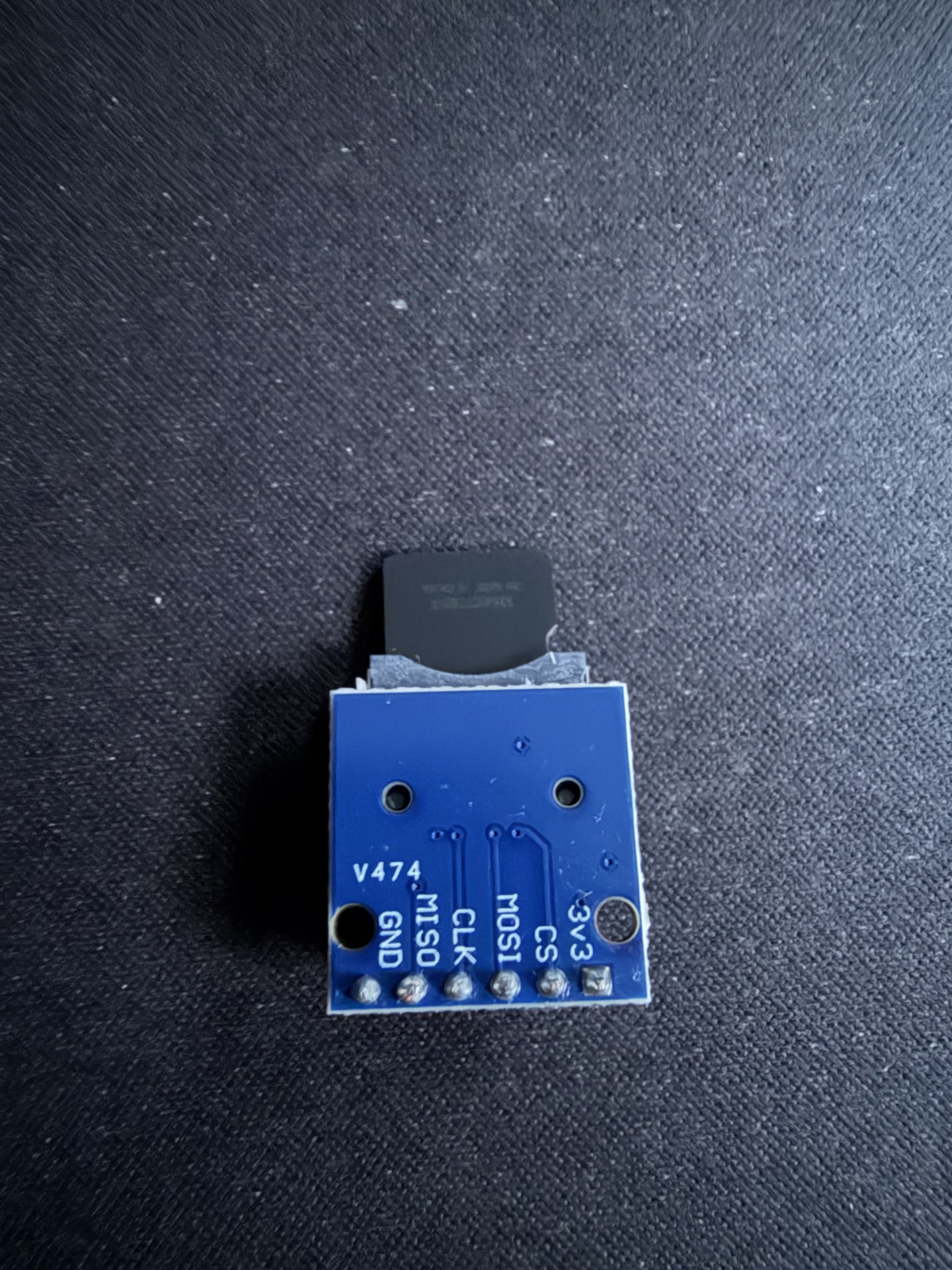 | 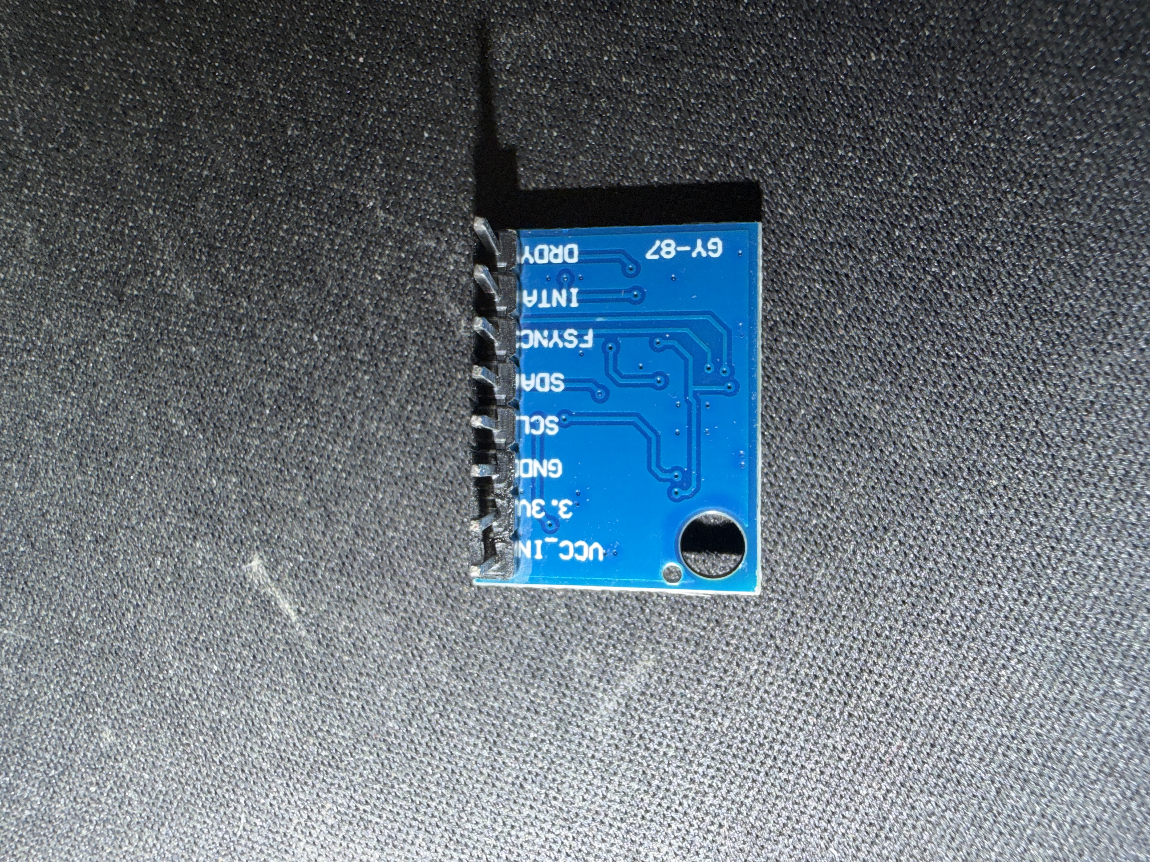 | 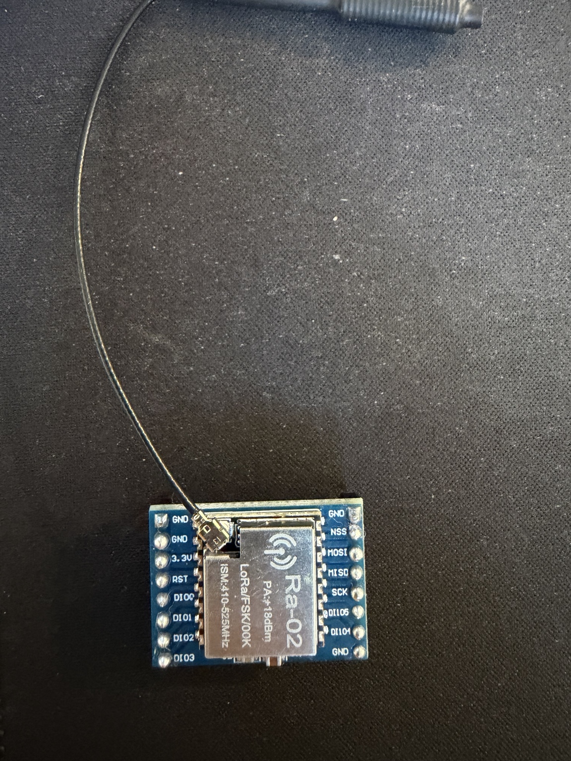 |
| Active buzzer |
|---|
 |
The Power Deck provides:
Power Deck envelope:
30 × 85.5 mm| INA219 | MP1584 |
|---|---|
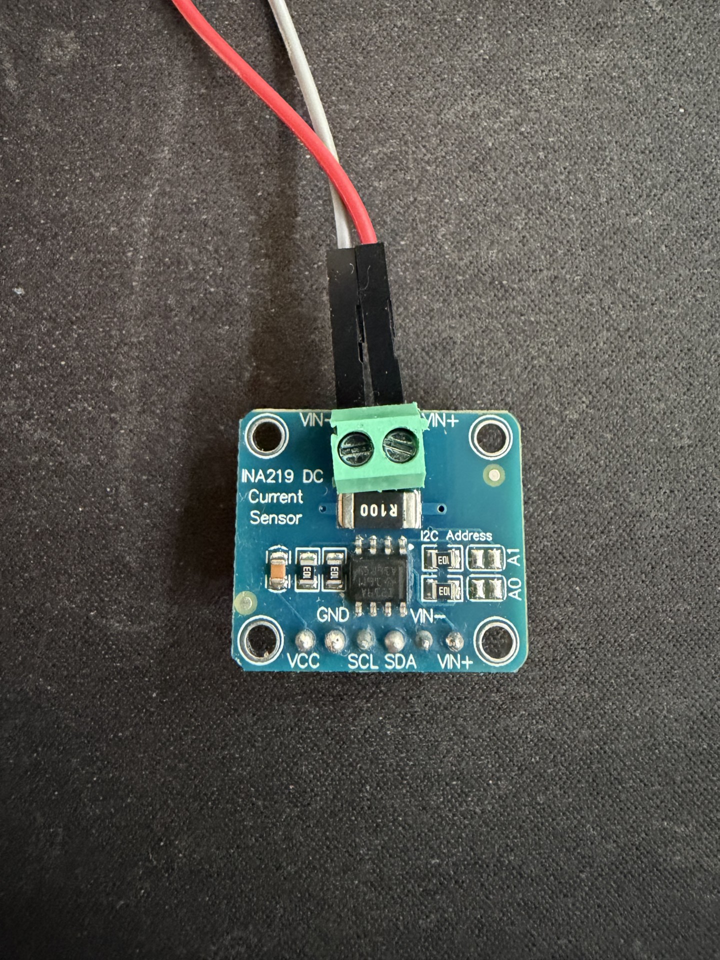 | 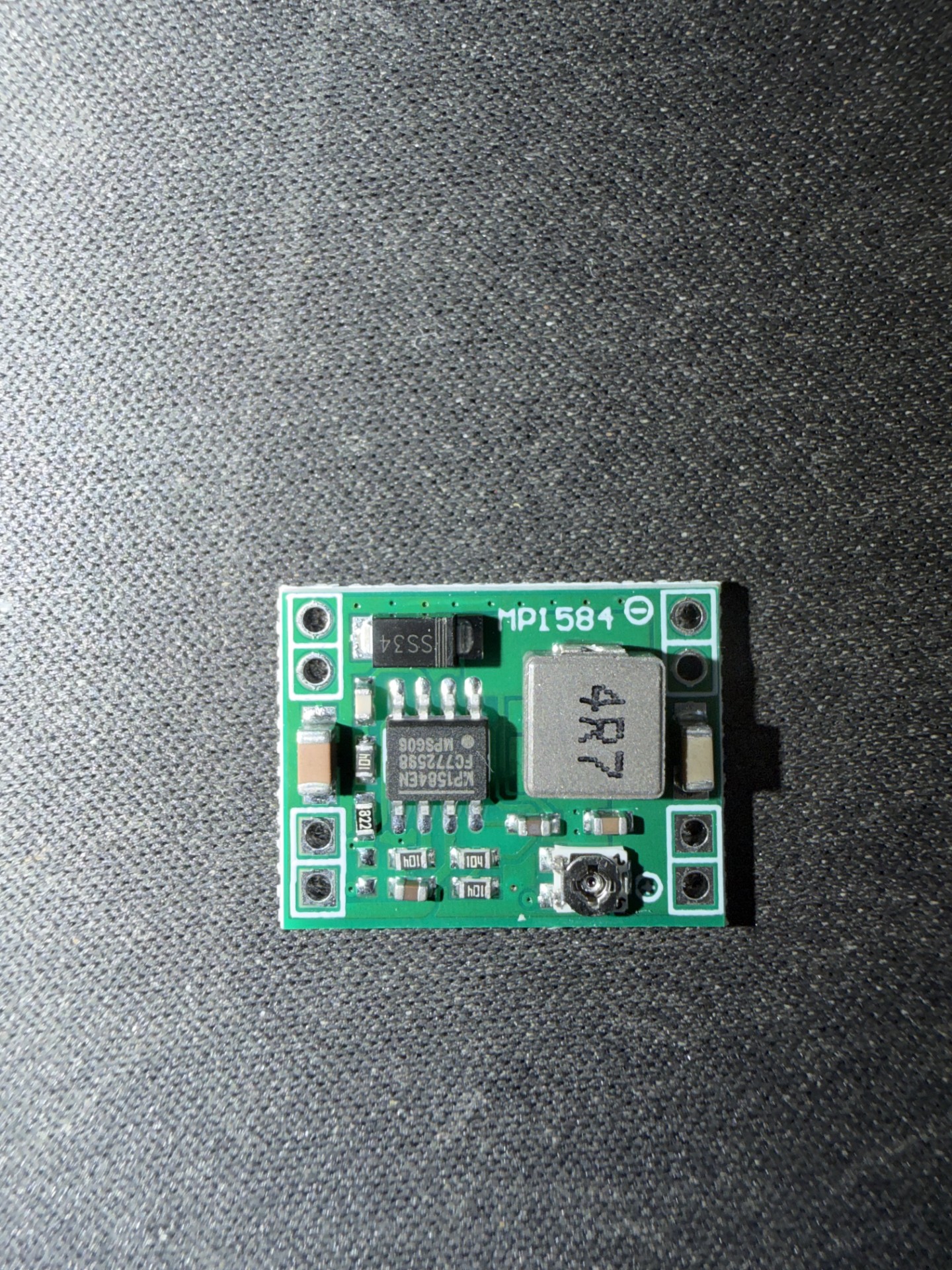 |
Current Mk1 development battery:
Tattu 2S 550 mAh LiPo
7.4 V nominal
8.4 V maximum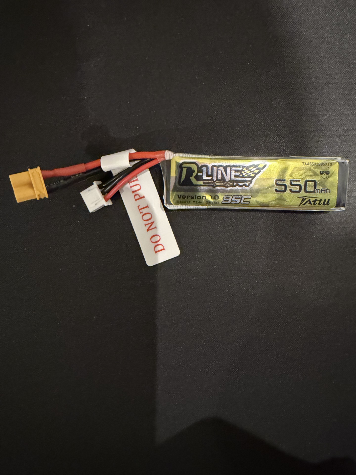
The battery is mechanically retained independently of the PCBs.
The current Mk1 electrical architecture is split between two longitudinal PCBs.
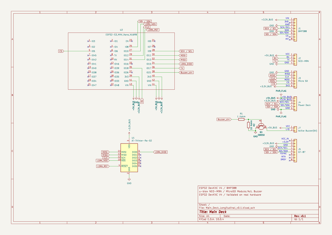
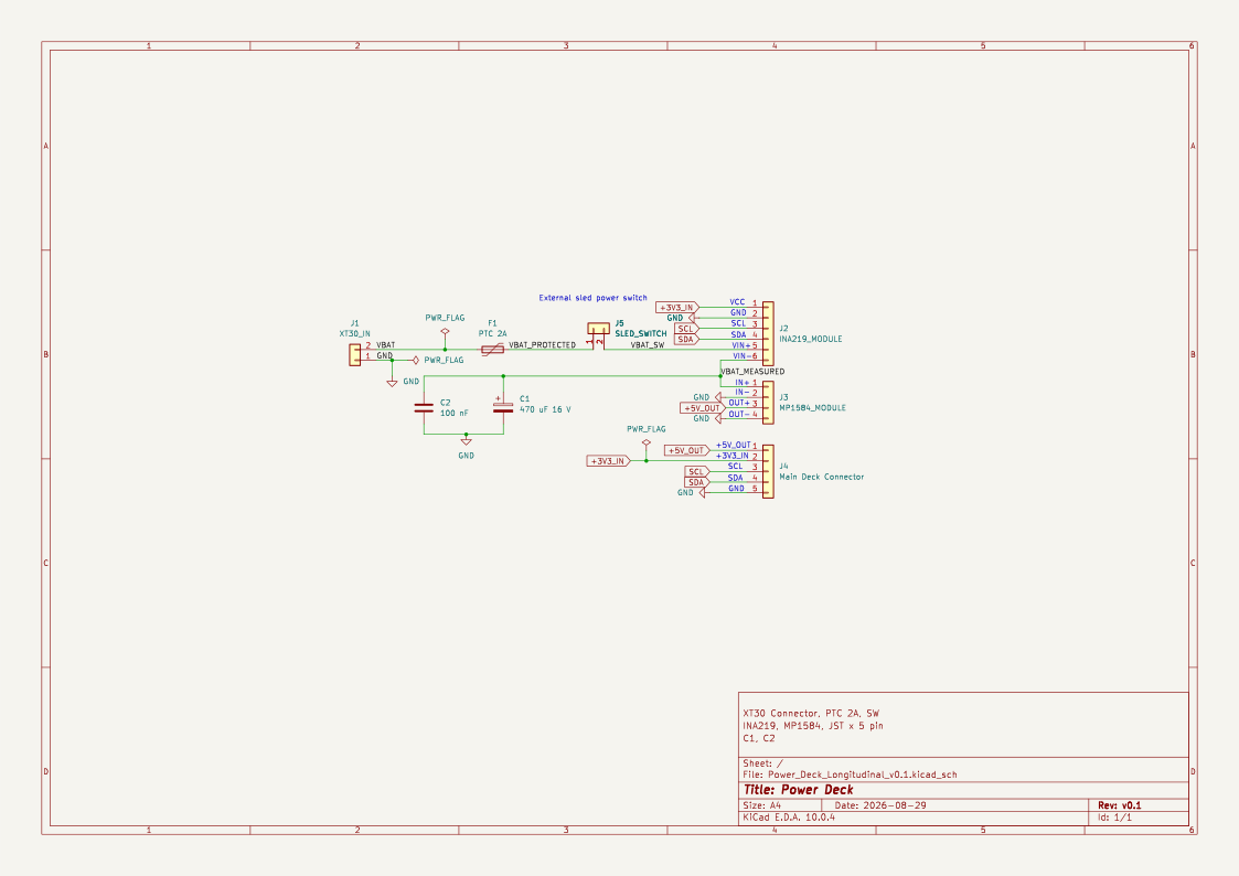
The schematic SVGs are exported from the current KiCad source.
Earlier flighttelemetry-v*.png schematics are retained in docs/schematics/ for historical traceability and do not represent the current Mk1 architecture.
                     2S LiPo
                        |
                        v
              +-------------------+
              |    Power Deck     |
              |                   |
              | PPTC Protection   |
              | Main Switch       |
              | INA219            |
              | MP1584            |
              +---------+---------+
                        |
               +5V / I2C / GND
                        |
                        v
              +-------------------+
              |     Main Deck     |
              |                   |
              | ESP32-S3 N16R8    |
              | BMP388 @ 0x76     |
              | NEO-M9N           |
              | MicroSD           |
              | GY-87             |
| Ra-02 / SX1278 |The two PCBs are designed for longitudinal installation in a mechanical sled.
The final sled geometry remains under development.
| Function | ESP32-S3 GPIO |
|---|---|
| GPS RX | 17 |
| GPS TX | 18 |
| I2C SDA | 8 |
| I2C SCL | 9 |
| SPI MOSI | 11 |
| SPI MISO | 13 |
| SPI SCK | 12 |
| MicroSD CS | 5 |
| LoRa NSS | 10 |
| LoRa RESET | 14 |
| LoRa DIO0 | 15 |
| Buzzer control | 21 |
MicroSD and LoRa share the SPI bus and use independent chip-select signals.
Integrated MicroSD + LoRa operation still requires bench validation.
DS18B20 support remains in the firmware but is disabled in the current Mk1 configuration.
The Mk1 shared I2C bus has been bench validated with the current module set:
| Device | Address | Status |
|---|---|---|
| INA219 | 0x40 | Detected |
| GY-87 MPU-6050 | 0x68 | Detected and identified |
| External BMP388 | 0x76 | Detected and flight-firmware validated |
| GY-87 BMP180 | 0x77 | Detected and identified |
The external BMP388 uses SDO tied to GND to select address 0x76.
This establishes electrical coexistence on the shared bus. GY-87 sensor acquisition is not yet integrated into the flight firmware.
RocketOS implements the following flight-state sequence:
IDLE -> BOOST -> COAST -> APOGEE -> DESCENT -> LANDEDDetection currently uses BMP388 barometric altitude and derived climb rate.
This provides flight-event detection, not recovery deployment control.
Recovery actuation remains planned.
RocketOS currently supports:
Onboard logging operates independently from the telemetry transport.
MAVLink telemetry is currently implemented over USB Serial.
Implemented messages include:
| Message | Purpose |
|---|---|
| HEARTBEAT | Vehicle presence and link status |
| SYS_STATUS | System and battery status |
| GPS_RAW_INT | GNSS position and fix |
| GLOBAL_POSITION_INT | Position and relative altitude |
| GLOBAL_POSITION_INT_COV | Position with covariance |
| VFR_HUD | Speed, altitude and climb rate |
| BATTERY_STATUS | Battery voltage, current and SOC |
| HOME_POSITION | Home reference |
| STATUSTEXT | System and flight events |
Mk1 radio hardware:
Ai-Thinker Ra-02
SX1278-class
The radio interface is present in the Main Deck v0.1 hardware design.
LoRa transport is not yet implemented in the flight firmware.
RocketOS supports data-driven testing using altitude-vs-time flight profiles.
CSV flight profile
        |
        v
FlightStateMachine
        |
        v
Detected flight sequence
        |
        v
Expected result validation
Current profiles:
| Profile | Expected Apogee | Purpose |
|---|---|---|
estes_c6 | 253.9 m | Nominal flight |
midpower_machdip | 904.4 m | Barometric Mach-dip rejection |
low_apogee | 71.5 m | Low-altitude flight |
Current native regression result:
9 test cases
9 succeeded
The suite contains:
Run it with:
cd firmware/flight-computer
pio test -e native
If PlatformIO is not available globally on Windows, the project development environment can be invoked directly:
& "$env:USERPROFILE\.platformio\penv\Scripts\pio.exe" test -d "firmware\flight-computer" -e nativeThe Mk1 firmware contains an ESP32-S3 N16R8 PlatformIO target.
Build with:
& "$env:USERPROFILE\.platformio\penv\Scripts\pio.exe" run -d "firmware\flight-computer" -e esp32s3_n16r8Current validation:
Build: SUCCESS
Tests: 9 / 9 passed
Physical hardware identification of the current development module confirmed:
ESP32-S3
240 MHz
16 MB flash
~8 MiB PSRAM
Build success does not establish complete Mk1 hardware validation.
The Mk1 BatteryMonitor uses a 2S LiPo baseline:
| Voltage | Estimated SOC |
|---|---|
| 8.40 V | 100% |
| 8.20 V | 90% |
| 8.00 V | 80% |
| 7.80 V | 70% |
| 7.60 V | 60% |
| 7.40 V | 50% |
| 7.20 V | 40% / Warning |
| 7.00 V | 25% |
| 6.80 V | 10% / Critical |
| 6.60 V | 0% |
Below 5.0 V is treated as battery disconnected.
Bench validation on the historical development configuration demonstrated:
DISCONNECTED.CONNECTED / OK.This validates the BatteryMonitor behavior.
It does not validate the complete Mk1 Power Deck.
0x76.RocketOS Mk1 is therefore a prototype under integration, not a flight-qualified system.
Main Deck v0.1 and Power Deck v0.1 have been released for prototype fabrication.
Manufacturing baseline:
PCB:        FR4
Layers:     2
Size:       30 × 85.5 mm
Thickness:  1.6 mm
Copper:     1 oz
Finish:     Lead-free HASL
Mask:       Green
Silkscreen: White
Prototype order:
5 × Main Deck v0.1
5 × Power Deck v0.1
The exact manufacturing packages are retained in the repository.
The released Main Deck v0.1 fabrication package leaves BMP388 SDO unconnected. The five fabricated Main Deck v0.1 boards therefore require an SDO-to-GND rework when the BMP388 is installed.
The current KiCad source contains the corrected SDO-to-GND connection.
The released v0.1 fabrication package remains unchanged to preserve exact as-built traceability.
Fabrication release does not imply electrical or flight validation.
RocketOS/
|
+-- docs/
|   +-- Baseline/
|   +-- images/
|   +-- schematics/
|
+-- firmware/
|   +-- flight-computer/
|   +-- hardware-id-test/
|
+-- hardware/
|   +-- Mk1/
|       +-- Main_Deck_Longitudinal_v0.1/
|       +-- Power_Deck_Longitudinal/
|       +-- superseded/
|
+-- README.md
The authoritative project baseline is maintained under:
docs/Baseline/Key documents:
RocketOS_Master_Context.mdRocketOS_Architecture.mdRocketOS_System_Requirements.mdRocketOS_Project_History.mdRepository code, repeatable validation evidence and released hardware artifacts take precedence when determining implementation status.
RocketOS prioritizes:
The project intentionally distinguishes between:
IMPLEMENTED
DESIGN RELEASED
BENCH VALIDATED
PHYSICALLY INTEGRATED
FLIGHT VALIDATED
These states are not interchangeable.
The immediate development sequence is:
1. Validate buzzer transistor circuit
2. Validate Ra-02
3. Validate shared MicroSD + Ra-02 SPI bus
4. Validate complete Power Deck topology on the bench
5. Receive and inspect prototype PCBs
6. Bring up fabricated Power Deck
7. Bring up fabricated Main Deck, including BMP388 SDO-to-GND rework
8. Develop and validate longitudinal mechanical sled
9. Integrate GY-87 firmware acquisition
10. Integrate LoRa telemetry firmware
11. Complete integrated Mk1 bench validation
12. Real-flight validationMIT License
| Qty | Value | Footprint | References |
|---|---|---|---|
| 1 | 1 Kohm | Resistor_THT:R_Axial_DIN0207_L6.3mm_D2.5mm_P7.62mm_Horizontal | R1 |
| 1 | 10 Kohm | Resistor_THT:R_Axial_DIN0207_L6.3mm_D2.5mm_P7.62mm_Horizontal | R2 |
| 1 | Active Buzzer(5V) | Buzzer_Beeper:Buzzer_12x9.5RM7.6 | J7 |
| 1 | Ai-Thinker-Ra-02 | RocketOS_Mk1:Ra-02_SX1278 | U1 |
| 1 | BMP388 | RocketOS_Mk1:BMP388_MODULE | J1 |
| 1 | ESP32-S3_MINI_Nano_N16R8 | RocketOS_Mk1:ESP32-S3_MINI_Nano_N16R8 | U2 |
| 1 | GY-87 | RocketOS_Mk1:GY87 | J5 |
| 1 | Micro SD | RocketOS_Mk1:MicroSD | J3 |
| 1 | NEO-M9N | RocketOS_Mk1:NEO_M9N_MODULE | J2 |
| 1 | Power Deck | Connector_JST:JST_XH_B5B-XH-A_1x05_P2.50mm_Vertical | J4 |
| 1 | S8050 | Package_TO_SOT_THT:TO-92_Inline | Q1 |
dgtaheno/RocketOS
ESP32 flight computer with MAVLink telemetry, QGroundControl integration, GPS, BMP388 altimetry, INA219 power monitoring and fault-tolerant SD logging

xDocka15/GNSS_geret
Dokument popisuje zmeny/upravy v elektronike gnss-geret z 2024 tak aby vznikla jednodoskova prenostitelna verzia.


averywallis/Feather-NEO-M9N-GPS
KiCad files for a NEO-M9N GPS Featherwing

Project-SkyFall/CanSat-2023
This is repository for Czech CanSat team Project SkyFall

DashSight/Pine64-Mezzanine-Card
A PineA64 mezzanine card for adding support to communicate with a vehicle's OBD2 port, obtain GPS location and determine acceleration, designed in KiCAD

Sphyrna-029/Pico-Pilot
A simple auto pilot for land/water based robots based on the Raspberry Pi rp2350B/2354B

daedalus-ind/icarus-hardware
Hardware of the onboard flight computer for the Icarus rocket.

DevKiDCosmo/SATELLITE-EDGE-MODULE
A satellite edge module ready for competition
It measures 30 × 85.5 mm and has 2 copper layers, 1.6 mm thick.
11 parts, built around the NEO-M9N-00B, BMP388 and S8050. The full list of its parts is on this page, with links to each part's symbol and footprint where PCBKit's library has them.
From the dgtaheno/RocketOS repository on GitHub, at the commit this page was made from: the board is hardware/Mk1/Main_Deck_Longitudinal_v0.1/Main_Deck_Longitudinal_v0.1.kicad_pcb and its schematic hardware/Mk1/Main_Deck_Longitudinal_v0.1/Main_Deck_Longitudinal_v0.1.kicad_sch. PCBKit opens the board in the browser, with nothing to install.
Its repository publishes it under the MIT licence: you may reuse it on that licence's terms (keep the author's notice, and for a copyleft licence share your changes alike).