4 layers160 × 100 mm
Z80 Simple Computer
apws/261103-reto-comp-andrew-grok-kicad
Rebuilt Z80 educational schematic in KiCad. The board is not routed yet.
38 parts1
 devinacker/upd7801-reader1
ROM reader for NEC µCOM-87 (uPD7801 series) microcontrollers
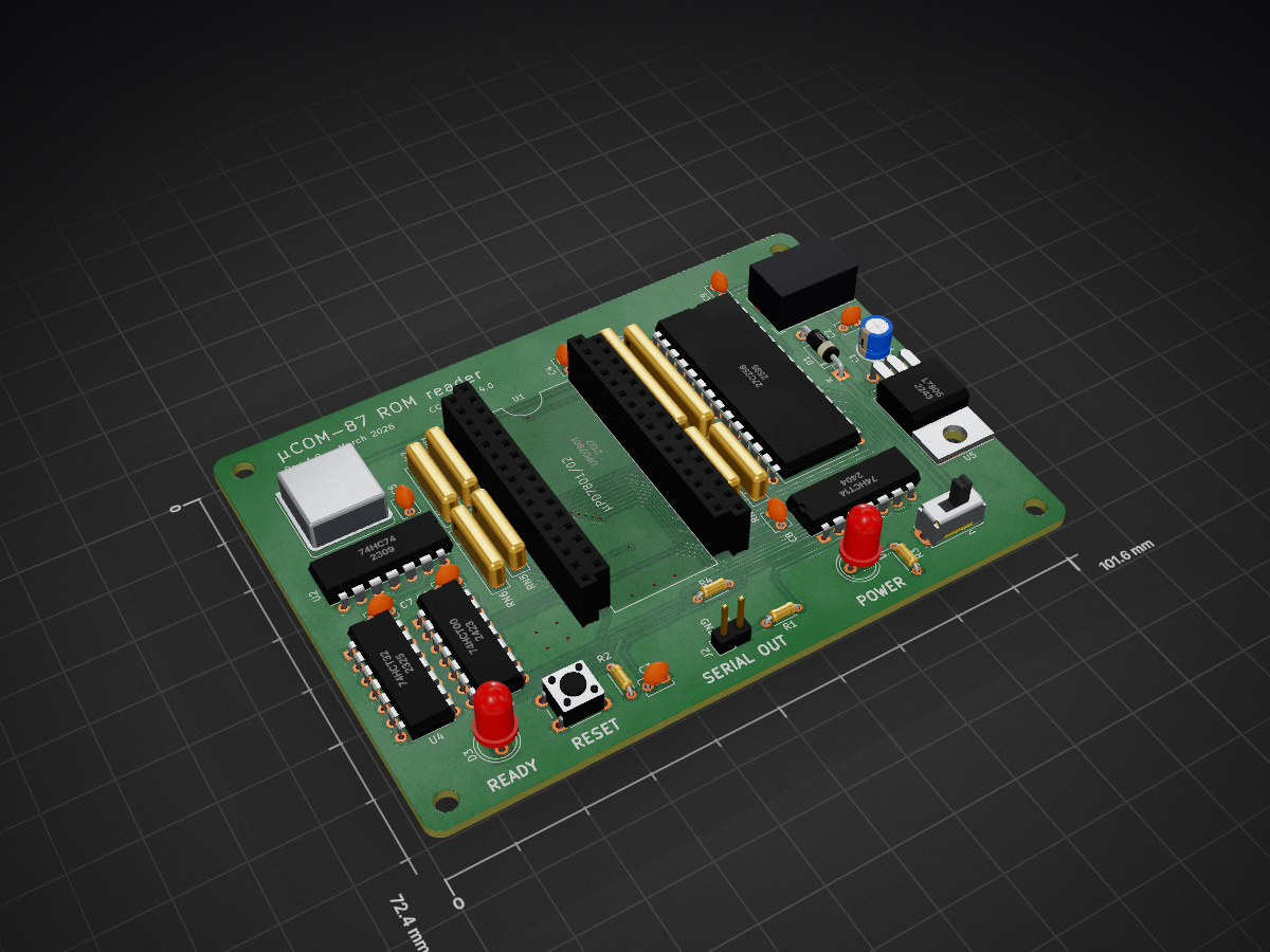
Upd7801-reader is an open-source printed circuit board by devinacker, from the devinacker/upd7801-reader repository on GitHub. It is a 2-layer board of 101.6 × 72.4 mm with 40 parts on 87 nets, routed with 471 tracks and 29 vias.
It is built around the 27C256-17/J, 74HC74D and 74HCT00D, with the 74HCT14D, 74HCT32D and L7805 among its other parts. Its parts include 9 capacitors, 7 ICs, 4 resistors, 3 diodes and 2 connectors.


This is a PCB designed to read the internal mask ROM contents from NEC "µCOM-87" microcontrollers (µPD7801 aka uPD7801, etc.) and automatically output them in Intel hex format over serial.
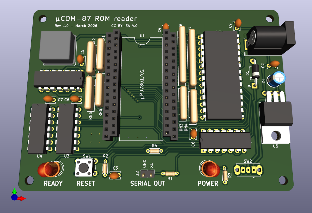
Zipped gerbers and ROM are available from the releases page.
The resulting Intel hex file can be converted to a raw ROM image using objcopy, SRecord, or similar tools.
Unlike its successor, the uPD7810 series, these chips don't have any mode pins for enabling or disabling the chip's internal ROM. As a result, on the 7801 and 7802, it's normally enabled all the time, and the chips can't be repurposed as ROMless parts.
However, after some testing, it was found that overclocking the chip above a certain level will effectively disable the internal ROM, causing instructions to be fetched from external memory even within the normally-internal address range. This board exploits that effect and boots into external ROM by doing this:
M1 & A13 & !RD), switch to normal clock and enable EPROMNote that this setup is somewhat dependent on the temperature of the chip. During testing, it tended to work long enough to perform a few consecutive dumps via the reset button, but once it has been powered on for a minute or so, the clock glitching will probably become unreliable or stop working (no LED activity). If this happens, just leave the power off for a few minutes.
Alternately, you might find that a slower clock (~8-10) is more stable, but will probably require briefly waiting for the chip to warm up a bit. Be sure to adjust your serial baud rate and possibly also adjust the output timing in the ROM (e.g. add an extra NOP to Serial_WriteByte to get 31250 baud with a 10 MHz clock, or 25000 baud with a 8 MHZ clock).
This board has been used to successfully dump a couple of different chips so far, but I still consider it a proof of concept. If there's enough interest I may revisit it to try to make it more stable.
| Ref | Part |
|---|---|
| C1 | 0.22µF electrolytic |
| C2, C3, C4, C5, C6, C7, C8, C9 | 0.1µF ceramic |
| D1 | 1N4001 |
| D2 | generic 5mm 2V LED (power) |
| D3 | generic 5mm 2V LED (status) |
| J1 | generic 3-pin barrel jack |
| J2 | 1x2 pin header, 2.54mm |
| R1, R2, R3, R4 | 1k ohm, 1/8 watt |
| RN1, RN2 | 5-pin 1k ohm SIP resistors |
| RN3, RN4, RN5, RN6 | 5-pin 22k ohm SIP resistors |
| RN7, RN8 | 9-pin 22k ohm SIP resistors |
| SW1 | generic 6mm tactile switch (optional, for reset) |
| SW2 | OS102011MS2QN1 |
| U1 | µPD7801/02, 64-pin QUIP (four 1x16 2.54mm machined pin sockets recommended) |
| U2 | 74HC74 |
| U3 | 74HCT00 |
| U4 | 74HCT32 |
| U5 | LM7805 |
| U6 | 74HCT14 |
| U7 | 27C256 EPROM or compatible |
| X1 | 11.0592MHz oscillator, 5V HCMOS, DIP8 |
Use this board at your own risk. It was designed to be simple, but assumes you have basic experience working with electronics, including soldering. I am not responsible if you happen to blow something up.
PCB design and schematics are released under the Creative Commons Attribution-ShareAlike 4.0 (CC BY-SA) license. The firmware source (in the rom directory) is released as public domain.
| Qty | Value | Footprint | References |
|---|---|---|---|
| 8 | 0.1uF | Capacitor_THT:C_Disc_D3.8mm_W2.6mm_P2.50mm | C2, C3, C4, C5, C6, C7, C8, C9 |
| 4 | 1k | Resistor_THT:R_Axial_DIN0204_L3.6mm_D1.6mm_P5.08mm_Horizontal | R1, R2, R3, R4 |
| 4 | 22k x 4 | Resistor_THT:R_Array_SIP5 | RN3, RN4, RN5, RN6 |
| 2 | 1k x 4 | Resistor_THT:R_Array_SIP5 | RN1, RN2 |
| 2 | 22k x 8 | Resistor_THT:R_Array_SIP9 | RN7, RN8 |
| 1 | 0.22uF | Capacitor_THT:CP_Radial_D5.0mm_P2.50mm | C1 |
| 1 | 11.0592 MHz | Oscillator:Oscillator_DIP-8 | X1 |
| 1 | 1N4001 | Diode_THT:D_DO-41_SOD81_P10.16mm_Horizontal | D1 |
| 1 | 27C256 | Package_DIP:DIP-28_W15.24mm | U7 |
| 1 | 74HC74 | Package_DIP:DIP-14_W7.62mm | U2 |
| 1 | 74HCT00 | Package_DIP:DIP-14_W7.62mm | U3 |
| 1 | 74HCT14 | Package_DIP:DIP-14_W7.62mm | U6 |
| 1 | 74HCT32 | Package_DIP:DIP-14_W7.62mm | U4 |
| 1 | Conn_Coaxial_Power | Connector_BarrelJack:BarrelJack_Wuerth_6941xx301002 | J1 |
| 1 | L7805 | Package_TO_SOT_THT:TO-220-3_Horizontal_TabDown | U5 |
| 1 | POWER | LED_THT:LED_D5.0mm | D2 |
| 1 | READY | LED_THT:LED_D5.0mm | D3 |
| 1 | SERIAL | Connector_PinHeader_2.54mm:PinHeader_1x02_P2.54mm_Vertical | J2 |
| 1 | SW_Push | Button_Switch_THT:SW_PUSH_6mm | SW1 |
| 1 | SW_SPST | Button_Switch_THT:SW_Slide_1P2T_CK_OS102011MS2Q | SW2 |
| 1 | uPD7801 | quip64:Package_QUIP64 | U1 |
The 36 most common of 40 parts.
It measures 101.6 × 72.4 mm and has 2 copper layers, 1.6 mm thick.
40 parts, built around the 27C256-17/J, 74HC74D, 74HCT00D and 74HCT14D. The full list of its parts is on this page, with links to each part's symbol and footprint where PCBKit's library has them.
From the devinacker/upd7801-reader repository on GitHub, at the commit this page was made from: the board is upd7801-reader.kicad_pcb and its schematic upd7801-reader.kicad_sch. PCBKit opens the board in the browser, with nothing to install.
Its repository states no licence, so its author keeps all rights: ask devinacker before reusing the design.
apws/261103-reto-comp-andrew-grok-kicad
Rebuilt Z80 educational schematic in KiCad. The board is not routed yet.

roberto314/EVA-1_Reproduction
Recreation of the very rare K-K Systems EVA-1 Display Adapter for the Epson HX-20 Computer


ksr/p8x
Generated by generators/genkicad.py from the canonical geneagle netlist (CARDS["peripheral-card"]), same standard as the memory card: 4-layer (F/B signals, In1=GND, In2=VCC planes), a bypass cap above each IC, a…

MicroLind-Developers/microlind-hw
Hardware repository for the microlind project

sittner/tinyfs
TinyFS is a minimalist filesystem designed for extremely constrained embedded systems. The initial reason to create this project was the attempt to build a filesystem that can run on a ZX81 without any additional…
