4 layers33.2 × 33.2 mm
Pendant
picafe/pendant
A pendant built from two PCBs: a 8×8 bicolor LED matrix module (red, orange, green) and controller board with battery charging, USB-C power, 5 V boost, and motion sensing.
46 parts

 devcexx/chiquito
Smol development / testing board for STM32C071
Chiquito is an open-source printed circuit board by devcexx, from the devcexx/chiquito repository on GitHub. It is a 4-layer board of 15.4 × 25.5 mm with 17 parts on 37 nets, routed with 238 tracks and 15 vias.
It is built around the STM32C071G8U6, TLV75733PDRV and 161N-4PVS11, with the MBR120VLSFT1G-TP among its other parts. Its parts include 5 capacitors, 3 resistors, 3 connectors, 2 ICs and 2 diodes. It belongs with the STM32 boards of this library.


Chiquito is a simple, small, development board for the STM32C071 processors.
The STM32C071 processors are the only ones in the STM32C0 line that has an internal accurate 48 MHz crystal oscillator, that allows to run the processor with USB capabilities without the need of an external crystal. This is great for small projects where you're looking to reduce the BOM.
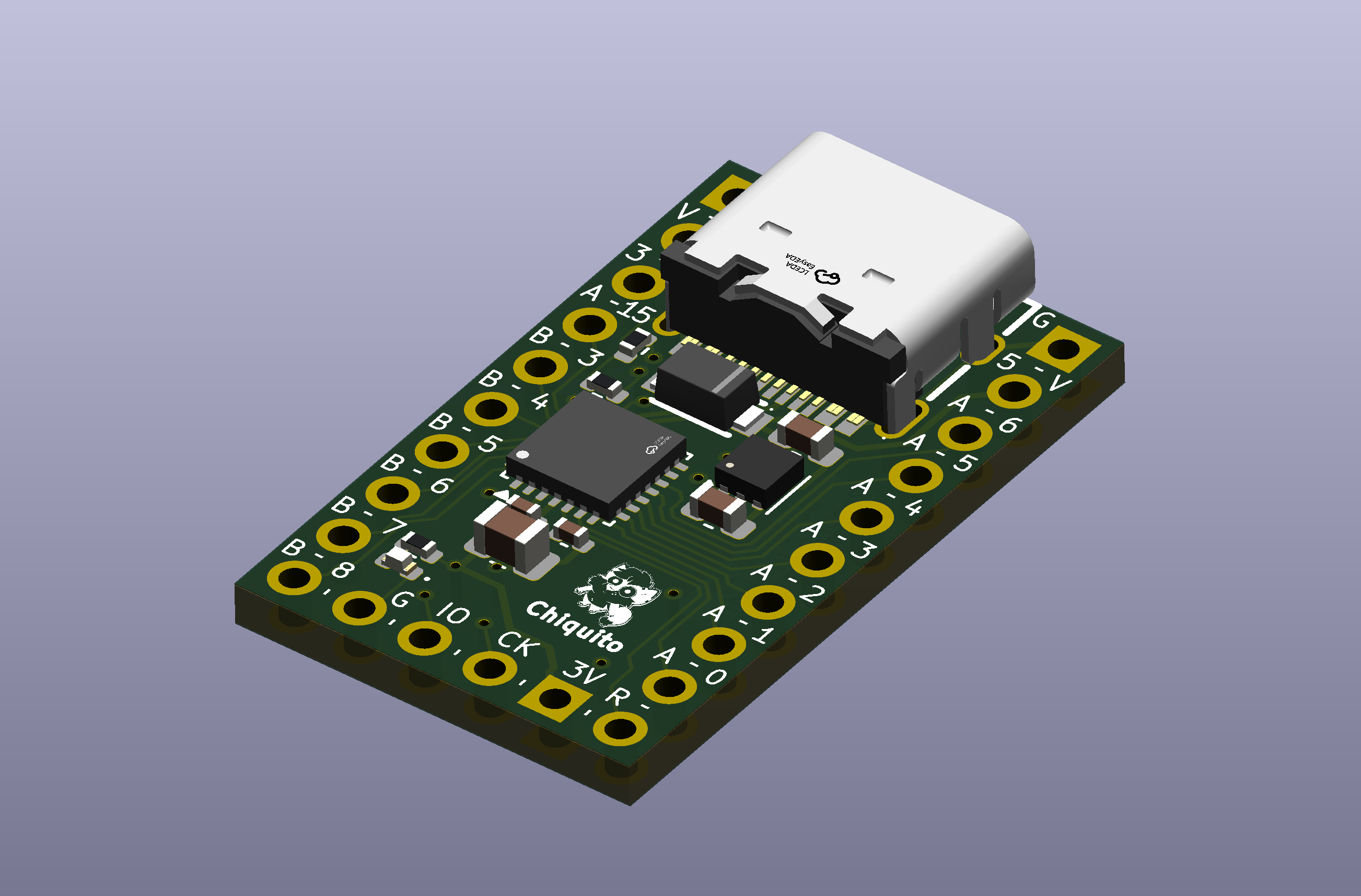
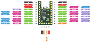
Image pinout is a simplification. Check the original datasheet for the complete information
Production files are available in the production folder. Fabrication has been tested with JLCPCB, therefore it is the recommended way to go.
Since JLCPCB prices are the same for 2 and 4 layer board, this design uses a 4 layer board where both inner layers are just ground planes, for better control of the signal integrity and USB impedance matching. Other providers may price you more for this number of layers.
Before sending to fabrication, always make sure that all the production files, BOM and PCBA positioning files are correct and up-to-date. As a hobby project, no responsability is taken for failures in the fabrication process or in the behavior of the final board.
By default, on the first connection, the device should boot into DFU mode.
If you don't have handy a ST-Link programmer and you're planning to use DFU as your main way for uploading new firmware, you must use the STM32CubeProgrammer and set to 0 the nBOOT_SEL option before uploading any firmware, so you can enter into DFU mode by just driving the BOOT0 pin low. Otherwise, after the first firmware upload, you won't be able to access the DFU mode unless you own a ST-Link programmer.
You may use either the STM32 DFU mode or an ST-link programmer to upload new firmware:
By default, entering into DFU will require you to manually set the nBOOT0 pin to 1 using a ST-Link programmer, and then reboot the device. You may change this behavior by setting the nBOOT_SEL option to 0, so you can enter into DFU mode by just driving the BOOT0 pin low.
For using a ST-Link programmer, connect the it to the debugging pins located
at the bottom of the board (GND, SWDIO, SWDCLK and +3V3).
| Qty | Value | Footprint | References |
|---|---|---|---|
| 2 | 100n | Capacitor_SMD:C_0402_1005Metric | C2, C5 |
| 2 | 4.7u | Capacitor_SMD:C_0603_1608Metric | C3, C4 |
| 2 | 5k1 | Resistor_SMD:R_0402_1005Metric | R1, R2 |
| 2 | Conn_01x10 | EasyEDA:PinHeader_1x10_P2.54mm_Vertical_Slim | J2, J3 |
| 1 | 161N-4PVS11 | EasyEDA:USB-C-SMD_HANELECTRICITY_161N-4XVS11 | USB1 |
| 1 | 1k5 | Resistor_SMD:R_0402_1005Metric | R3 |
| 1 | 4.7u | Capacitor_SMD:C_0805_2012Metric | C1 |
| 1 | Conn_01x04 | EasyEDA:PinHeader_1x04_P2.54mm_Vertical_Slim | J1 |
| 1 | LED | LED_SMD:LED_0402_1005Metric | D2 |
| 1 | LOGO | LOGO | G*** |
| 1 | MBR120VLSFT1G | EasyEDA:SOD-123F_L2.8-W1.8-LS3.7-RD | D1 |
| 1 | STM32C071G8U6 | Package_DFN_QFN:QFN-28_4x4mm_P0.5mm | U3 |
| 1 | TLV75733PDRV | Package_SON:WSON-6-1EP_2x2mm_P0.65mm_EP1x1.6mm | U2 |
It measures 15.4 × 25.5 mm and has 4 copper layers, 1.6 mm thick.
17 parts, built around the STM32C071G8U6, TLV75733PDRV, 161N-4PVS11 and MBR120VLSFT1G-TP. The full list of its parts is on this page, with links to each part's symbol and footprint where PCBKit's library has them.
From the devcexx/chiquito repository on GitHub, at the commit this page was made from: the board is chiquito.kicad_pcb and its schematic chiquito.kicad_sch. PCBKit opens the board in the browser, with nothing to install.
Its repository states no licence, so its author keeps all rights: ask devcexx before reusing the design.
picafe/pendant
A pendant built from two PCBs: a 8×8 bicolor LED matrix module (red, orange, green) and controller board with battery charging, USB-C power, 5 V boost, and motion sensing.

StaRadian/sutterspeed
USB light oscilloscope (STM32C071, 400 kS/s photodiode front end) with a Windows viewer and camera shutter speed measurement

Ozonised/FeroFlyF405
FeroFlyF405 an open source STM32F405 based flight controller running INAV


leonwip/ubiquitous-waddle
Dual channel CANnectivity CAN FD to USB-C adapter

proegssilb/lightsaber-hardware
PCBs and other files for lightsaber soundboard hardware.

HexSense-MIT/HS_ESP32_CAM_module
A custom designed USB camera module, with ESP32-S3R8 + OV2640. This will be used for the HexSenseCAM payload.