4 layers45 × 45 mm

 StaRadian/sutterspeed
USB light oscilloscope (STM32C071, 400 kS/s photodiode front end) with a Windows viewer and camera shutter speed measurement
Sutterspeed is an open-source printed circuit board by StaRadian, from the StaRadian/sutterspeed repository on GitHub. It is a 4-layer board of 36 × 12.8 mm with 35 parts on 42 nets, routed with 325 tracks and 52 vias.
It is built around the TEMD5510FX01, ME6211C33M5G-N and STM32C071G8U6, with the USBLC6-2SC6 among its other parts. Its parts include 14 capacitors, 13 resistors, 4 ICs, 2 connectors and 1 diode. It belongs with the sensors and measurement boards and the STM32 boards of this library.


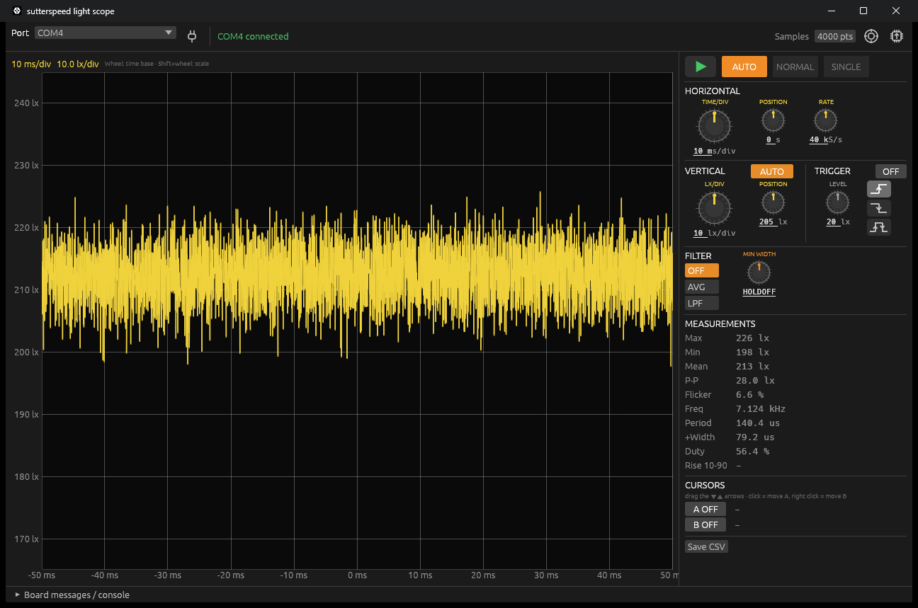
A light oscilloscope on a small USB board: a photodiode front end sampled at 400 kS/s, a Windows viewer that works like a bench scope (time base, vertical scale, trigger, filters, measurements, cursors), and a shutter measurement mode that times a single light pulse — the original purpose of the board was testing camera shutter speeds.
KiCad 10 project in kicad/, fabrication files (BOM, positions, Gerbers) in kicad/production/.
| path | contents |
|---|---|
firmware/src | firmware: ADC/DMA acquisition, scope engine (trigger, decimation, roll, pulse capture), USB CDC command line |
firmware/tools/viewer-rs | Windows viewer (Rust, egui), also updates the firmware over USB |
firmware/test | host test of the scope engine with synthetic light pulses |
firmware/lib | CMSIS, STM32C0 HAL, TinyUSB (git submodules) |
code/ | STM32CubeMX pin configuration |
kicad/ | schematic and PCB |
Clone with the libraries:
git clone --recursive https://github.com/StaRadian/sutterspeed.gitDownload sutterspeed-viewer.exe from the releases, plug in the
board and pick its COM port.
.hex/.bin file can be written as well. From a script:
sutterspeed-viewer --flash [sutterspeed.hex] (no file: the built-in one), sutterspeed-viewer --update (viewer only).Build: the firmware first (firmware/build/sutterspeed.hex goes into the viewer), then
cd firmware/tools/viewer-rs && cargo build --release.
Build with STM32CubeCLT (arm-none-eabi-gcc, CMake, Ninja):
cd firmware
cmake -S . -B build -G Ninja
cmake --build build
See firmware/README.md for flashing and the serial protocol.
zero removes the dark offset only — cover the
sensor when using it.adc and gain show them).Copyright © 2026 StaRadian. All rights reserved. The libraries under firmware/lib keep their own licenses.
| Qty | Value | Footprint | References |
|---|---|---|---|
| 5 | 10k | Resistor_SMD:R_0402_1005Metric | R3, R5, R6, R9, R12 |
| 4 | 100nF | Capacitor_SMD:C_0402_1005Metric | C4, C6, C9, C10 |
| 3 | 100 | Resistor_SMD:R_0402_1005Metric | R10, R11, R14 |
| 3 | 1nF | Capacitor_SMD:C_0402_1005Metric | C11, C12, C14 |
| 3 | 1uF | Capacitor_SMD:C_0402_1005Metric | C2, C3, C5 |
| 2 | 10pF | Capacitor_SMD:C_0402_1005Metric | C8, C13 |
| 2 | 1k | Resistor_SMD:R_0402_1005Metric | R7, R13 |
| 2 | 5.1k | Resistor_SMD:R_0402_1005Metric | R1, R2 |
| 1 | 100k | Resistor_SMD:R_0402_1005Metric | R8 |
| 1 | 10uF | Capacitor_SMD:C_0603_1608Metric | C1 |
| 1 | 47pF | Capacitor_SMD:C_0402_1005Metric | C7 |
| 1 | BLM18PG221SN1D | Inductor_SMD:L_0603_1608Metric | FB1 |
| 1 | ME6211C33M5G-N | Package_TO_SOT_SMD:SOT-23-5 | U2 |
| 1 | PCB USB-C 14P | PCB_USBC:PCBTypeC_14P | J1 |
| 1 | STM32C071G8U6 | Package_DFN_QFN:QFN-28_4x4mm_P0.5mm | U1 |
| 1 | SWD | Connector:Tag-Connect_TC2030-IDC-NL_2x03_P1.27mm_Vertical | J2 |
| 1 | TEMD5510FX01 | personal:Vishay_TEMD5510FX01 | D1 |
| 1 | TLV9064IPWR | Package_SO:TSSOP-14_4.4x5mm_P0.65mm | U4 |
| 1 | USBLC6-2SC6 | Package_TO_SOT_SMD:SOT-23-6 | U3 |
It measures 36 × 12.8 mm and has 4 copper layers, 0.8 mm thick.
35 parts, built around the TEMD5510FX01, ME6211C33M5G-N, STM32C071G8U6 and USBLC6-2SC6. The full list of its parts is on this page, with links to each part's symbol and footprint where PCBKit's library has them.
From the StaRadian/sutterspeed repository on GitHub, at the commit this page was made from: the board is kicad/sutterspeed.kicad_pcb and its schematic kicad/sutterspeed.kicad_sch. PCBKit opens the board in the browser, with nothing to install.
Its repository states no licence, so its author keeps all rights: ask StaRadian before reusing the design.


picafe/pendant
A pendant built from two PCBs: a 8×8 bicolor LED matrix module (red, orange, green) and controller board with battery charging, USB-C power, 5 V boost, and motion sensing.


slopus/codex-keybored
A 100% vibe-coded hardware build: Fusion 360, six-layer KiCad PCB, STM32 firmware, and live JLC factory handoff.

GuzziFlipFlops/ESP32-Walkie-Talkie
An open source ESPNOW based walkie talkie with a 600 meter tested distance, with an OLED and multiple buttons to interact with

cornim/comfospot50
The schematic and PCB in this directory are the project-authored controller board design. The board is intended to interface an ESP32-C3 with the existing ComfoSpot panel.

dcbokonon/darknet-smao
Darknet SMAO: Meshtastic LoRa+BLE mesh node SAO for DEF CON 34