2 layers37.4 × 47.4 mm

 devbotas/pcb-wires-first
A wires-first home automation controllers
Gateway is an open-source printed circuit board by devbotas, from the devbotas/pcb-wires-first repository on GitHub, published under the CERN-OHL-S-2.0 licence. It is a 2-layer board of 47.4 × 77.4 mm with 27 parts on 57 nets, routed with 120 tracks and 14 vias.
Its parts include 7 resistors, 7 diodes and 6 connectors. It belongs with the home automation and IoT boards and the RP2040 boards of this library.
Wireless IoT sucks.
It's unreliable and breaks all the time. There's not such thing as reliable, maintenance-free, wireless IoT.
If it runs on batteries - that's even worse.
Another problem - central IoT hubs. If those break, lose connection, decides to reboot ar whatever - my smart house immediatelly becomes non-functional.
Put the analog wires first! So that light switches continue to operate even if smart features decide to stop working.
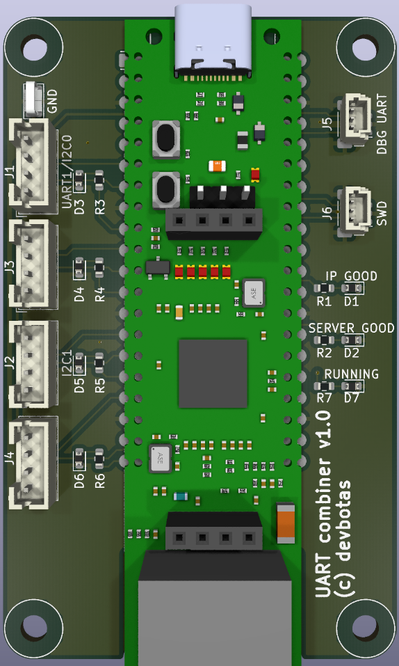
This is a simple carrier board for WizNET W55RP20 development module. It cannot do much by itself - maybe blink some LEDs. Real functionality (and also power) should come from the JST PH headers.
Can be mounted on M or L size Holey board.
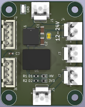
Takes 12-24V input (technically, 5-70V, but these voltages may not be supported on the other modules that this one is supposed to power) and creates 3.3V output so Gateway or other low power modules could be connected through the JST XH connector. Additionally, there are multiple JST VH connectors, which act as a power switch to connect multiple power hungry modules, like the Switcher.
Two can be mounted on a single Holey-S board.
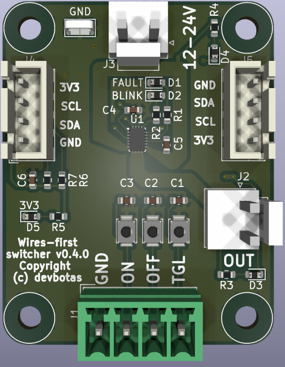
Originally meant to control LED lights, but it can switch anything. It has one switchable 12/24V output (should be able to handle 4A). Output can be controlled simultaneously in multiple ways:
The idea here that ON/OFF/TGL signals could be wired to the physical wall switches directly, any smart features being entirely optional. So the switch will operate as a dumb-switch.
Renesas HVPAK SLG47115 chip serves both as a high-power switch and an input sanitizer. For example, if faulty hardware shorts ON signal to GND permanently, OFF and TGL signals continue to operate normally.
Two can be mounted on a single Holey-S board.
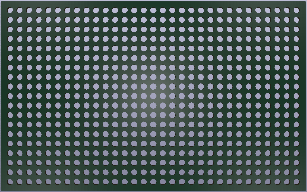
These are very handy to mount modules listed above, or maybe anything. They have a grid of 3.2mm diameter holes (hence the name) on a 5mm grid. They work perfectly with any M3 mounting hardware and come in the following sizes:
So, one M board can fit exactly two S boards, and one L board can fit exactly 2 M boards. This allows some neat and functional arrangement.
| Qty | Value | Footprint | References |
|---|---|---|---|
| 7 | 2.2k | Resistor_SMD:R_0603_1608Metric | R1, R2, R3, R4, R5, R6, R7 |
| 4 | MountingHole | MountingHole:MountingHole_3.2mm_M3_NoCopper | H1, H2, H3, H4 |
| 4 | ~ | Diode_SMD:D_0603_1608Metric | D3, D4, D5, D6 |
| 2 | Conn_01x03 | Connector_JST:JST_PH_B4B-PH-K_1x04_P2.00mm_Vertical | J3, J4 |
| 1 | DBG UART | Connector_JST:JST_SH_BM03B-SRSS-TB_1x03-1MP_P1.00mm_Vertical | J5 |
| 1 | GND | TestPoint:TestPoint_Keystone_5019_Miniature | TP1 |
| 1 | I2C1 | Connector_JST:JST_PH_B4B-PH-K_1x04_P2.00mm_Vertical | J2 |
| 1 | IP GOOD | Diode_SMD:D_0603_1608Metric | D1 |
| 1 | Jumper_2_Bridged | Jumper:SolderJumper-2_P1.3mm_Bridged_RoundedPad1.0x1.5mm | JP1 |
| 1 | RUNNING | Diode_SMD:D_0603_1608Metric | D7 |
| 1 | SERVER GOOD | Diode_SMD:D_0603_1608Metric | D2 |
| 1 | SWD | Connector_JST:JST_SH_BM03B-SRSS-TB_1x03-1MP_P1.00mm_Vertical | J6 |
| 1 | UART1/I2C0 | Connector_JST:JST_PH_B4B-PH-K_1x04_P2.00mm_Vertical | J1 |
| 1 | WizNet W55RP20 EVB Pico | Module:WizNet_W55RP20_EVB_Pico | A1 |
It measures 47.4 × 77.4 mm and has 2 copper layers, 1.6 mm thick.
27 parts. The full list of its parts is on this page, with links to each part's symbol and footprint where PCBKit's library has them.
From the devbotas/pcb-wires-first repository on GitHub, at the commit this page was made from: the board is pcb/gateway/gateway.kicad_pcb and its schematic pcb/gateway/gateway.kicad_sch. PCBKit opens the board in the browser, with nothing to install.
Its repository publishes it under the CERN-OHL-S-2.0 licence: you may reuse it on that licence's terms (keep the author's notice, and for a copyleft licence share your changes alike).

devbotas/pcb-wires-first
A wires-first home automation controllers


hackclub/OnBoard
💡 Join 1,000 teenagers and make your first PCB with a $100 grant!


CRImier/MyKiCad
My KiCad boards. Can't be bothered uploading individually anymore, so here you go.

pjgpetecodes/pico-streamdeck
This project is an OBS Controller using a Raspberry Pi Pico and CircuitPython.

freeDSP/freeDSP-aurora
freeDSP ADAU1452 with 8 analog input, 8 analog outputs, S/P-DIF I/O, ADAT I/O, USB Audio Class2, WiFi, Bluetooth

ugcs/ddc
Drone Show Software is software designed for drone shows, allowing flight path planning as well as control of dozens of drones simultaneously in a synchronized manner.