


4 layers33.1 × 64.7 mm

Team Greenbotics at WRO Future Engineers
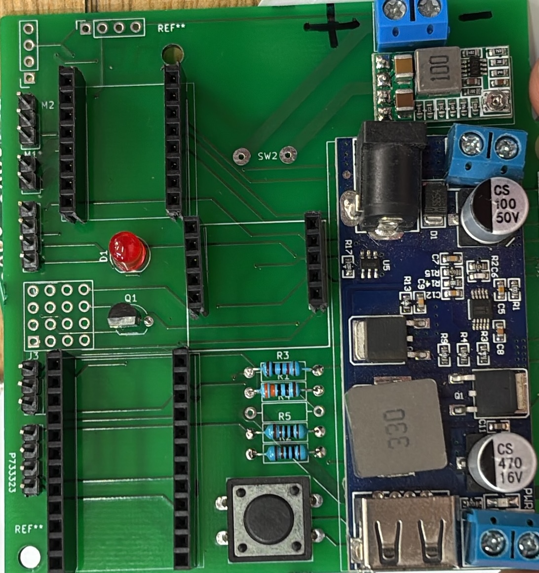
Models is an open-source printed circuit board by Devansh-awat, from the Devansh-awat/greenbotics repository on GitHub. It is a 2-layer board of 86 × 85 mm with 26 parts on 74 nets, routed with 435 tracks and 26 vias.
It is built around the VL53L1X and BC547. Its parts include 10 ICs, 5 resistors, 3 connectors, 2 switches and 1 diode.
 |
|---|
 |  |
|---|---|
| Scan QR to open Github repo | Scan QR to open YouTube video |
Welcome to the Greenbotics 2025 repository! This repository contains everything we've worked on over the past ten months, including all our code and resources. You can also use this repository as a complete guide to understand and reconstruct the robot from the ground up.
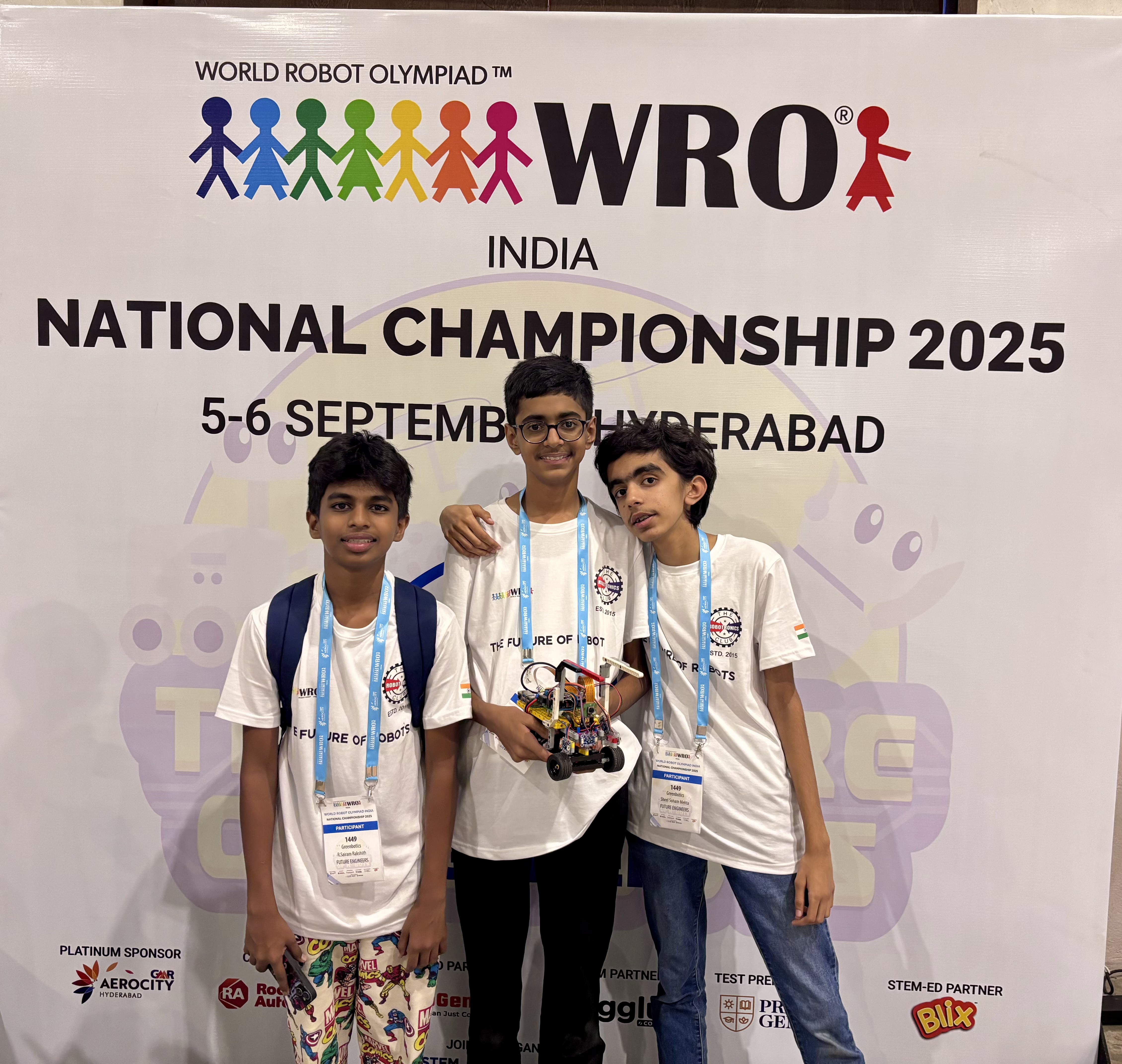
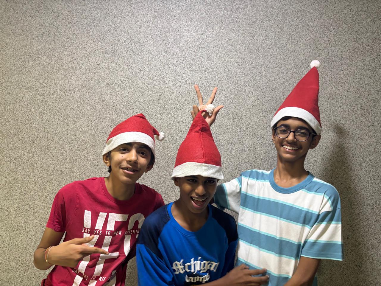
Yes. We did know the camera was on!
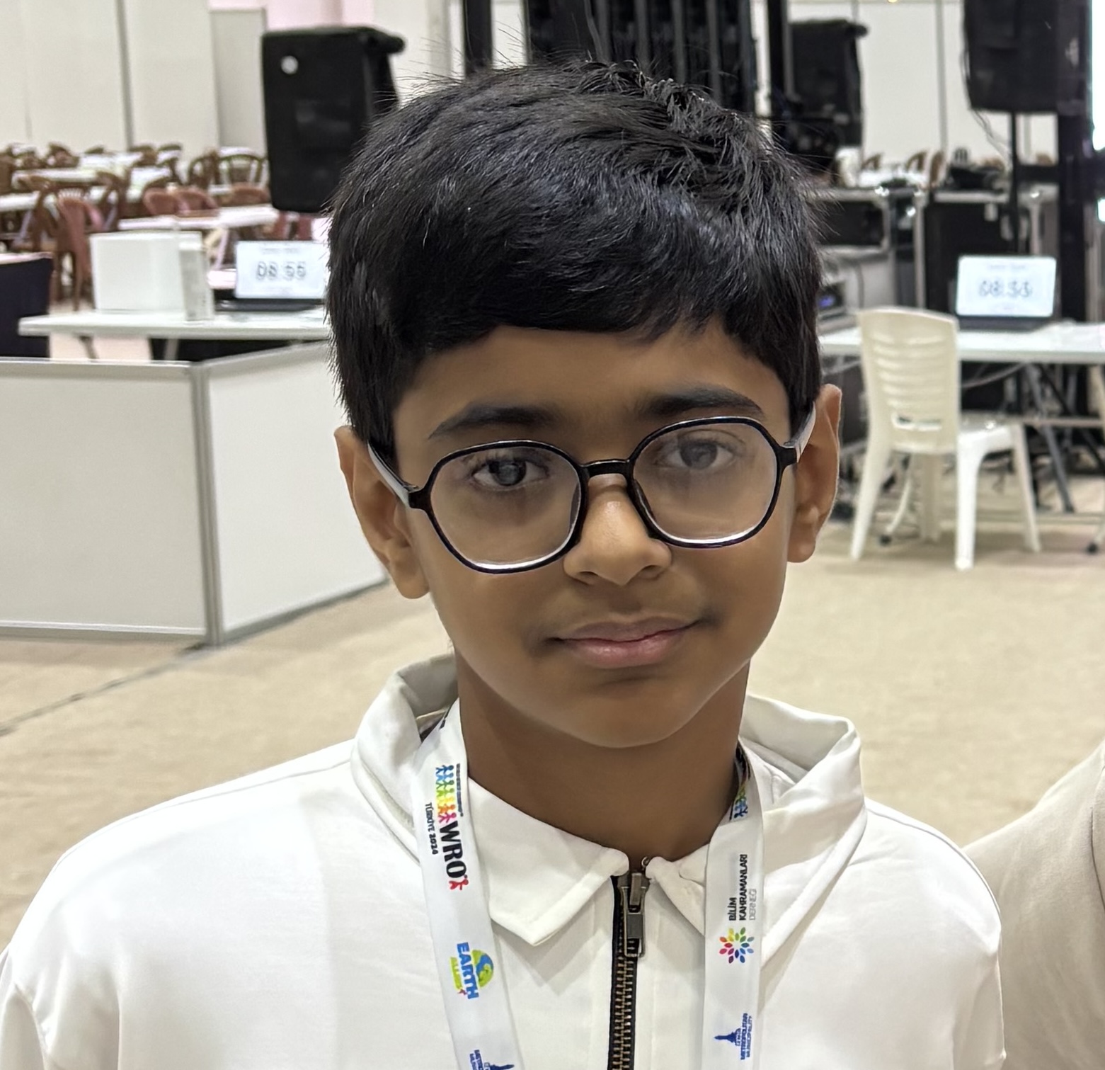 | Devansh Hi! I’m Devansh doing my second WRO season. Last year I represented India in the RoboMission category coming #25 in Internationals. This year I wanted a new challenge and learn new things. My hobbies are coding and robotics. |
|---|---|
 | Sheel Hi! I'm Sheel. I'm 15, and doing my second WRO season. Last year, our team made it to the International Finals in Robomission Junior. Additionally, I'm learning competitive debate. I also have a dog, and both of us are obsessed with Monkeys. |
 | Rakshith I'm Rakshith, a 9th grader passionate about robotics and aspiring to study engineering in Germany. I love building drones, experimenting with sensors. I also have 3 dogs, and two of them live with my grandparents in Hyderabad. |
 | Paresh Gambhava Mr. Paresh Gambhava is our chief coach from The Robotronics Club Ahmedabad. He is a robotics enthusiast, and electrical engineer by profession. He has vast experience training students for Robotics competition and projects. |
The Future Engineers Challenge for the 2026 WRO season involves designing and building an autonomous vehicle capable of completing two competition challenges.
The first challenge is the Open Challenge. In this challenge, the robot must autonomously complete three laps around the field while navigating between the outer boundary walls and the randomly positioned inner walls. The robot must maintain reliable navigation despite variations in the field layout and changing driving directions.
The second challenge is the Obstacle Challenge. In this challenge, red and green traffic signs are placed along the course. The robot must complete three laps while passing red traffic signs on the left side and green traffic signs on the right side. The robot must accurately detect the driving direction, avoid collisions, navigate around obstacles, and finish by parking within the designated parking area. The wall placement is fixed for this challenge.
Throughout the season, our goal is to develop a robot that combines reliable hardware, efficient software, and robust autonomous navigation. To prepare for possible surprise-rule modifications, our software is designed with a modular architecture that allows competition-specific parameters and behaviours to be adjusted quickly without major changes to the core navigation system.
Our passion for robotics, autonomous systems, and engineering inspired us to participate in the WRO Future Engineers challenge. Building on the experience gained in previous WRO seasons, we wanted to create a robot that is more capable, reliable, and engineered from the ground up.
One of our main goals this season was to move away from the largely LEGO-based construction used in previous years and develop a predominantly 3D-printed robot. Designing our own components gave us greater control over the robot's structure, weight distribution, sensor placement, and overall performance while helping us develop valuable CAD design, manufacturing, and prototyping skills.
Alongside the hardware, we focused on improving our autonomous navigation software through computer vision, sensor fusion, and real-time decision-making. Throughout the season, we continuously tested and refined our design to create a robot capable of reliably completing the competition challenges.
Beyond competition results, our goal is to strengthen our engineering, teamwork, and problem-solving skills while expanding our understanding of robotics and autonomous systems.
Technical Skills:
Soft Skills:
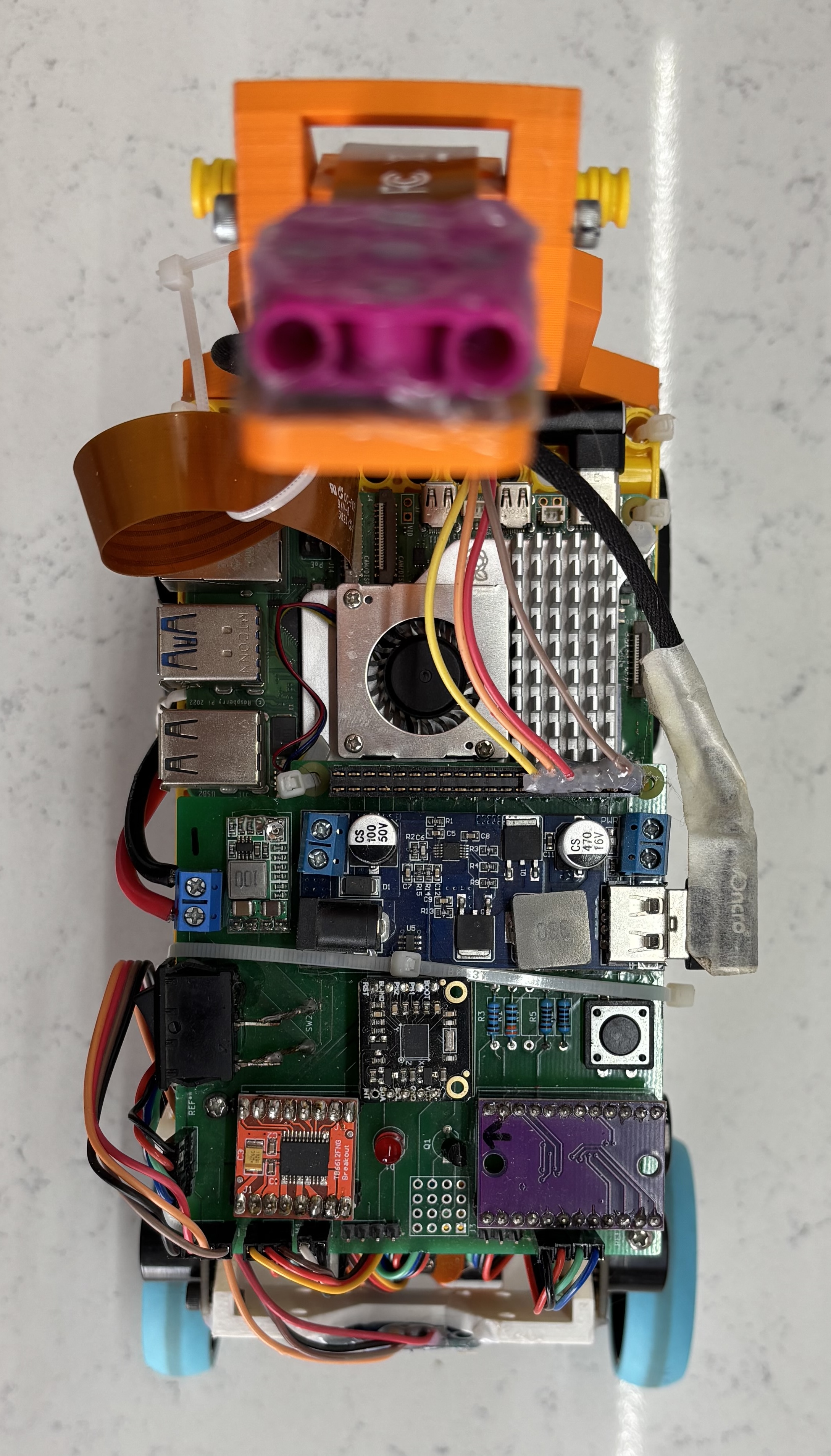
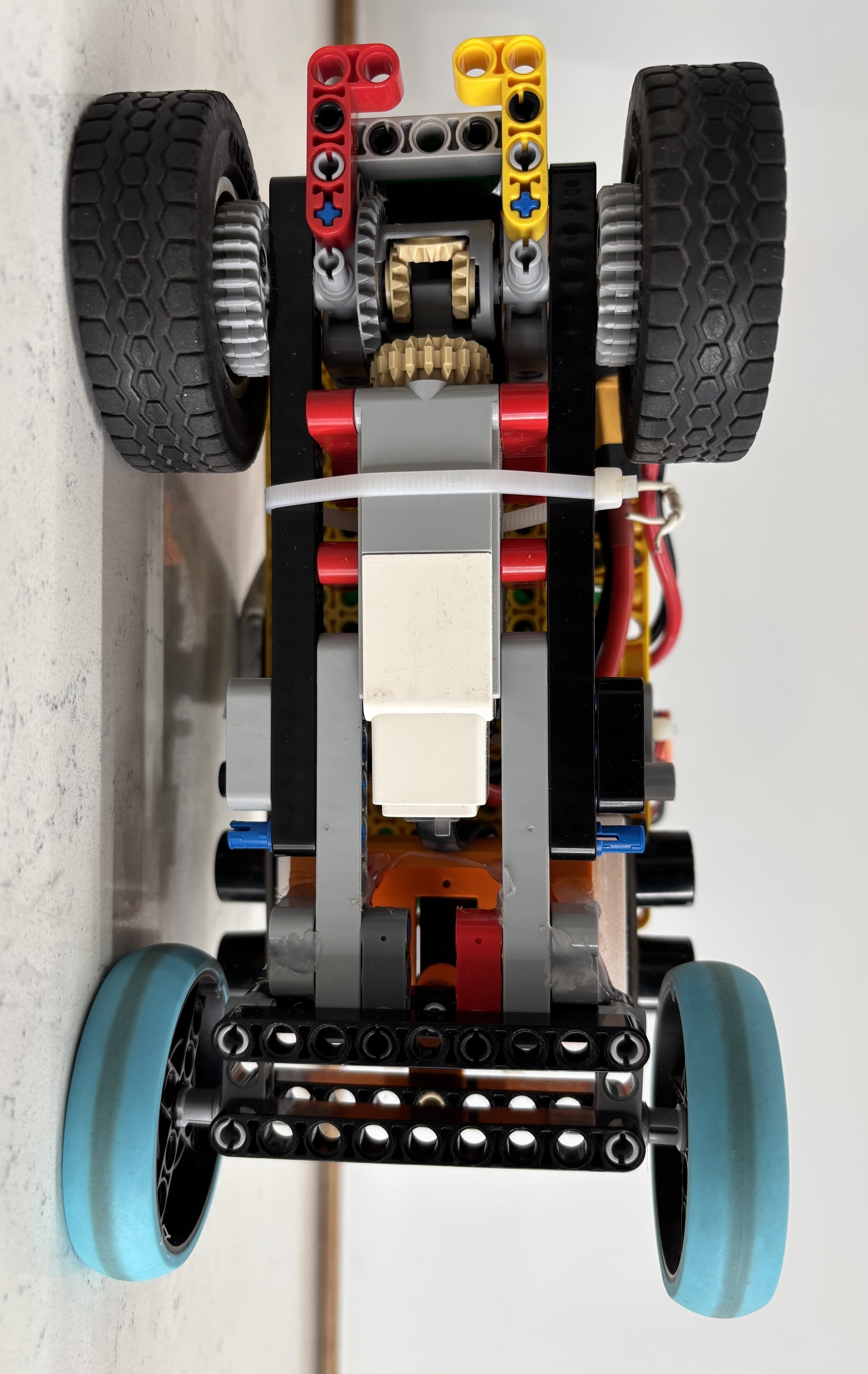
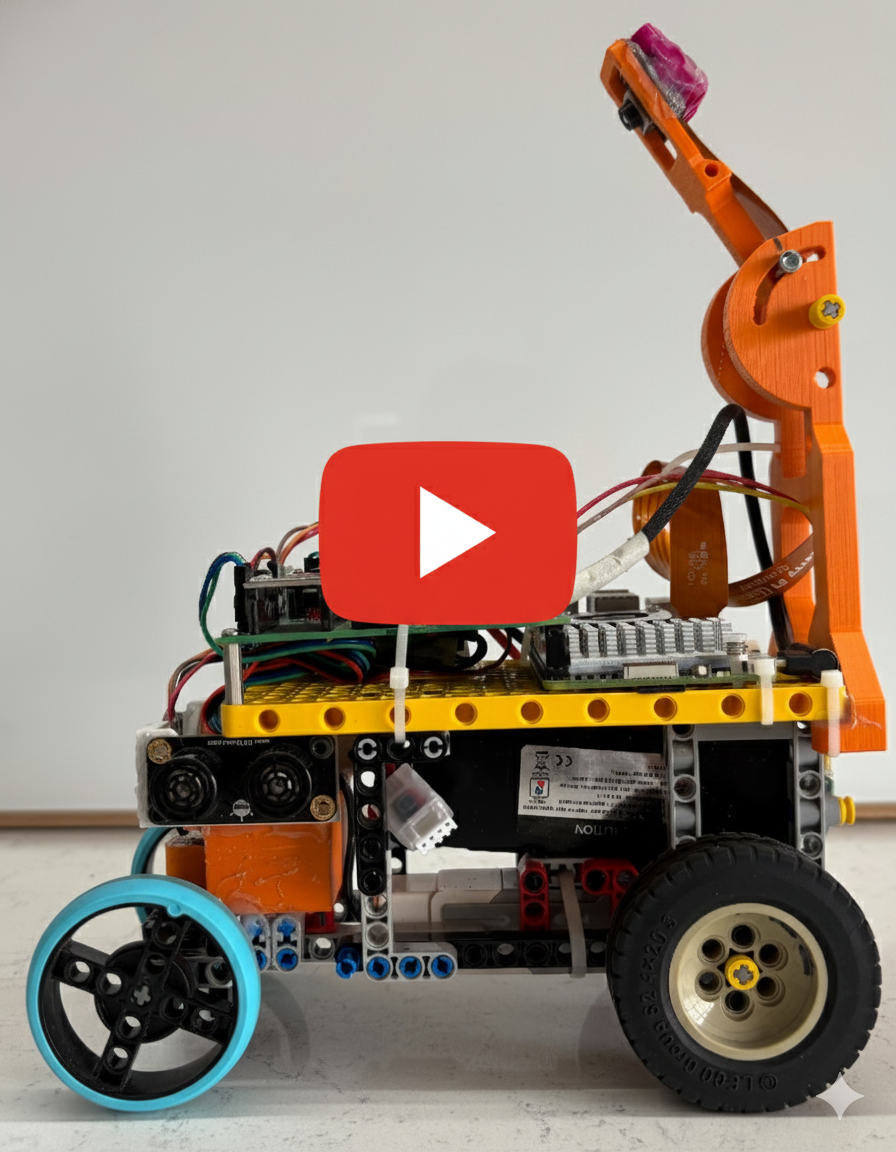
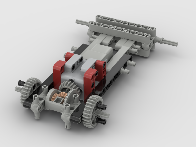
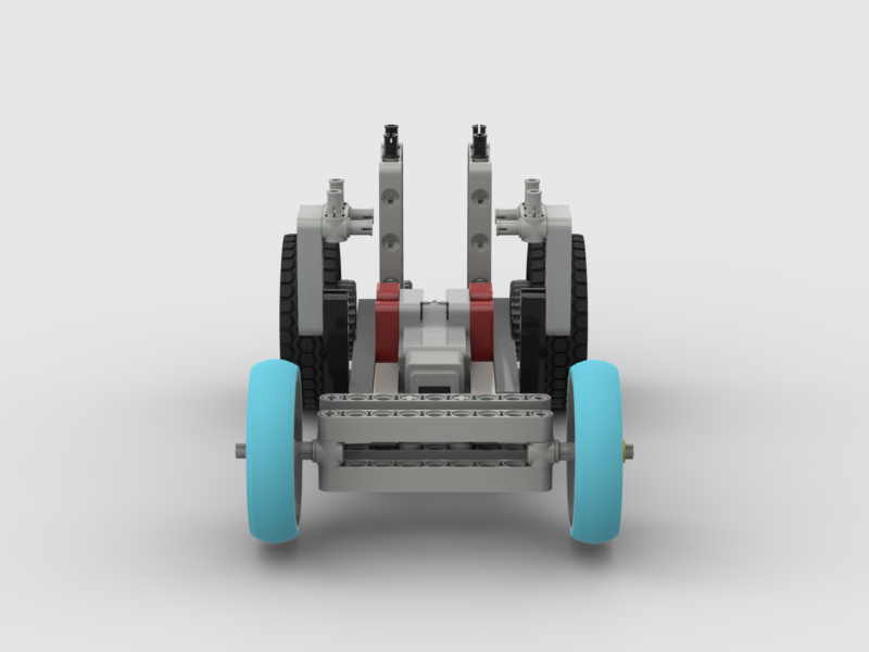
We designed our robot with Raspberry Pi 5 as the main brain of the car. Raspberry Pi 5 had pre-integrations with the camera allowing us to use faster smarter image procesing algorithms which is critical in this robots design. Having spent a lot of time working on LEGO-based hardware in the 2024 season, we chose to use many LEGO parts for our Robot's Hardware. However the robot also uses a Raspberry Pi, Raspberry Pi camera, and other off the shelf electronic components.
| Top view | Bottom view |
|---|---|
 |  |
| Front view | Rear view |
|---|---|
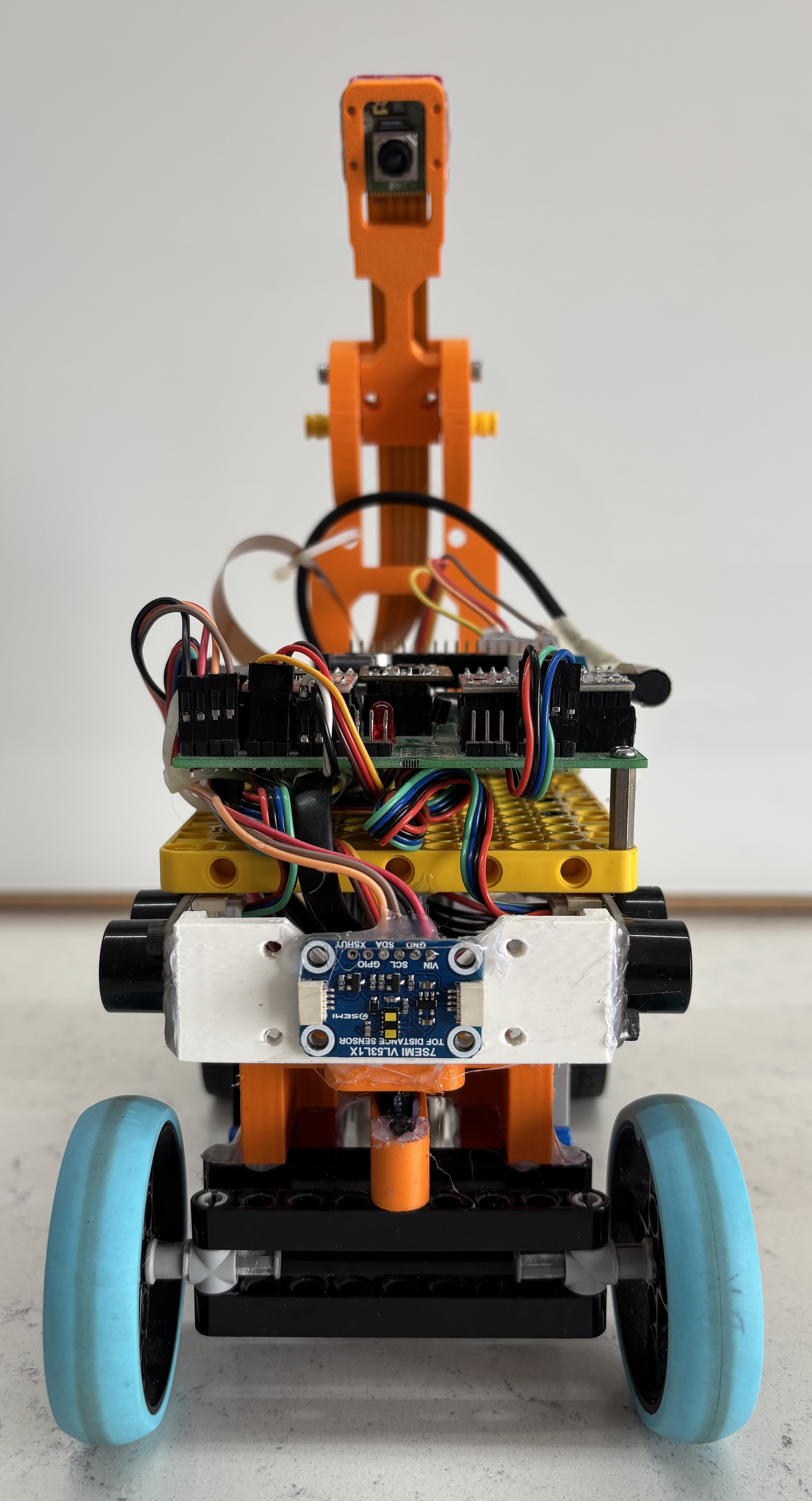 | 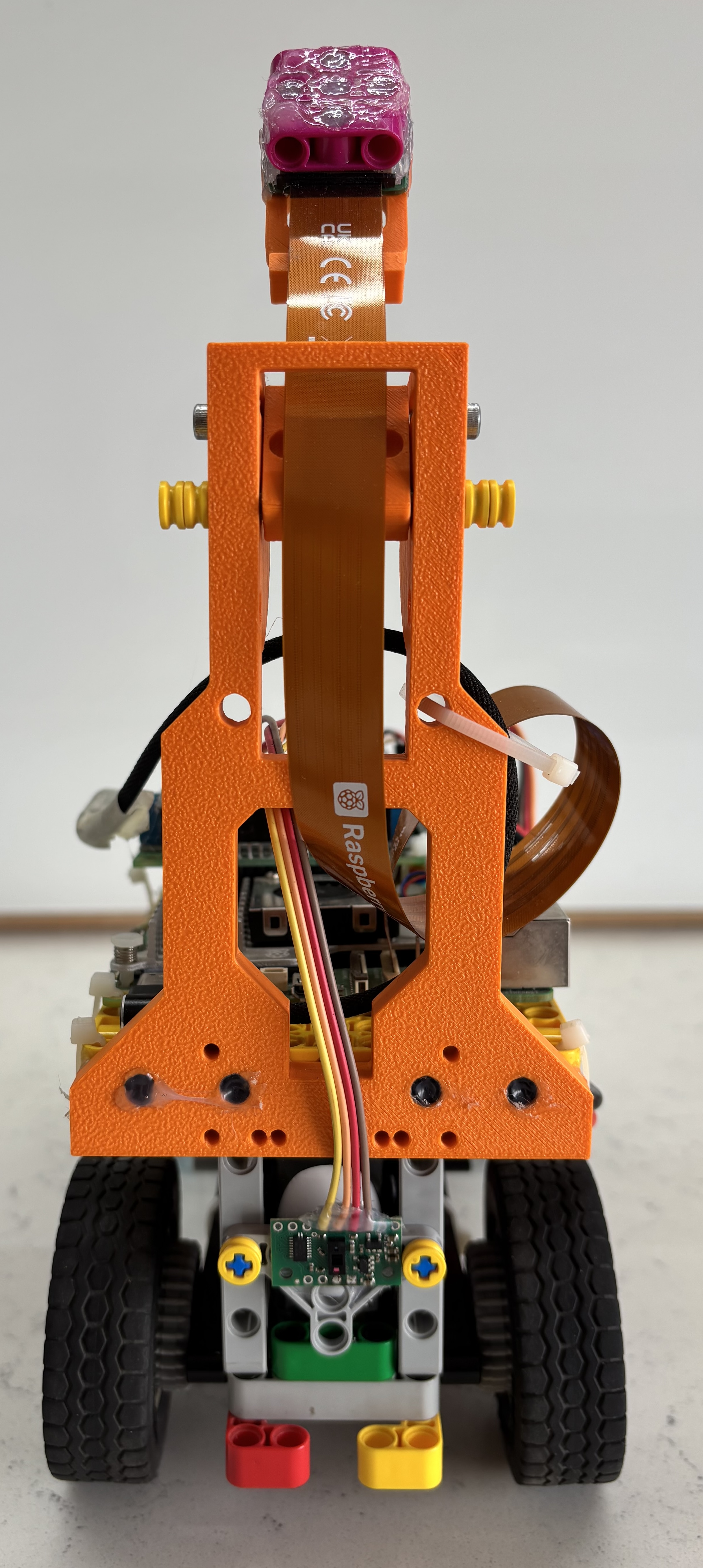 |
| Left view | Right view |
|---|---|
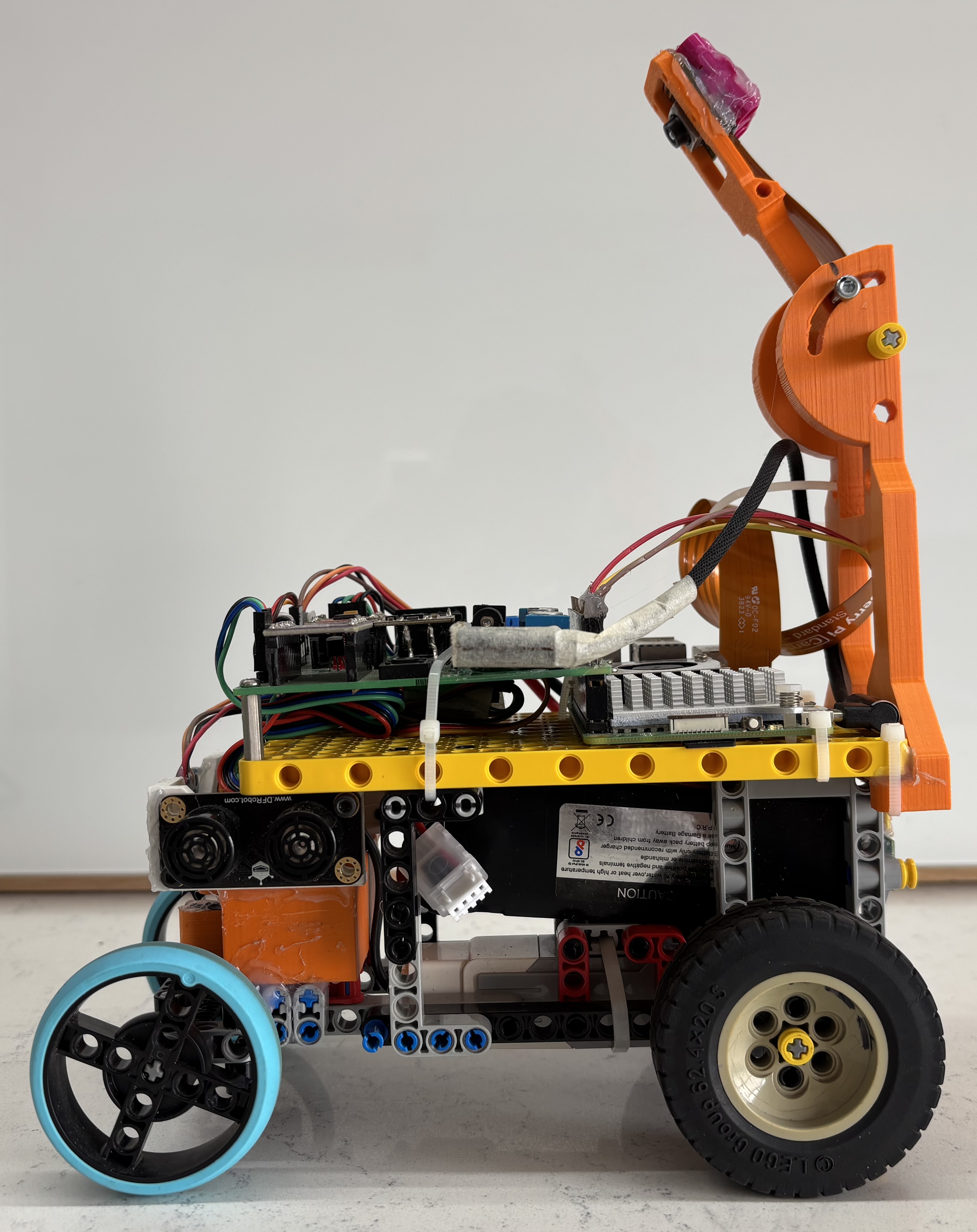 | 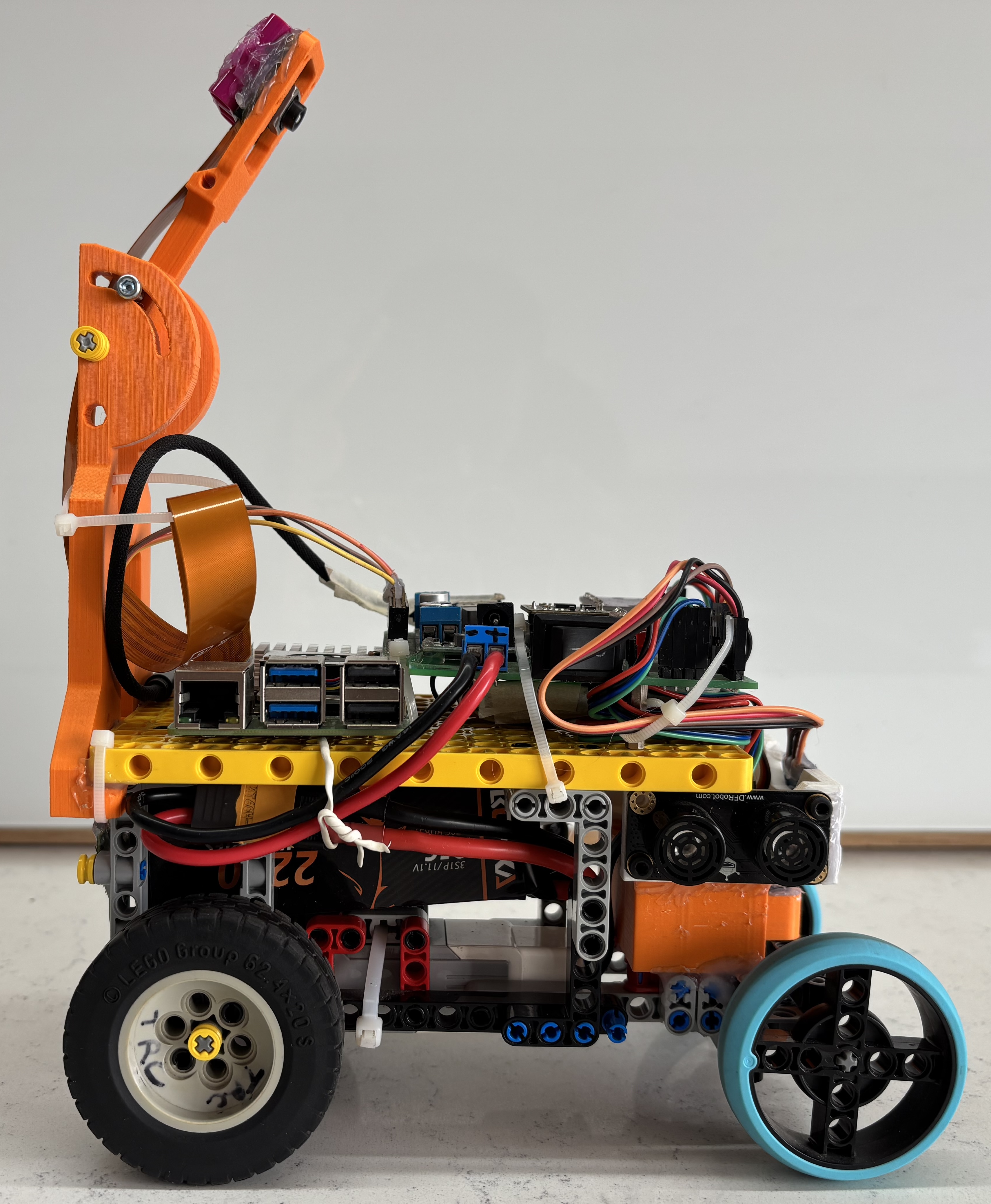 |
This playlist consists of 3 videos that show our robot's construction, open challenge run as well as obstacle challenge run.
 | Scan QR code to open in YouTube |
|---|
Our robot's mobility system is designed around a LEGO-based chassis that balances ease of assembly with reliable performance. We selected a LEGO EV3 Medium Motor for propulsion due to its compatibility with our modular design approach, delivering 240-250 RPM at 9V through a differential drivetrain that enables smooth turning by allowing wheels to rotate at different speeds. For precise steering control, we integrated an SG90 servo motor with a custom 3D-printed mount that connects to our LEGO chassis. The TB6612FNG motor driver manages power delivery and speed control, while all components are securely mounted to our LEGO framework using standard connectors and custom PCB integration. This design prioritizes modularity and maintainability while providing the torque and precision needed for autonomous navigation challenges.
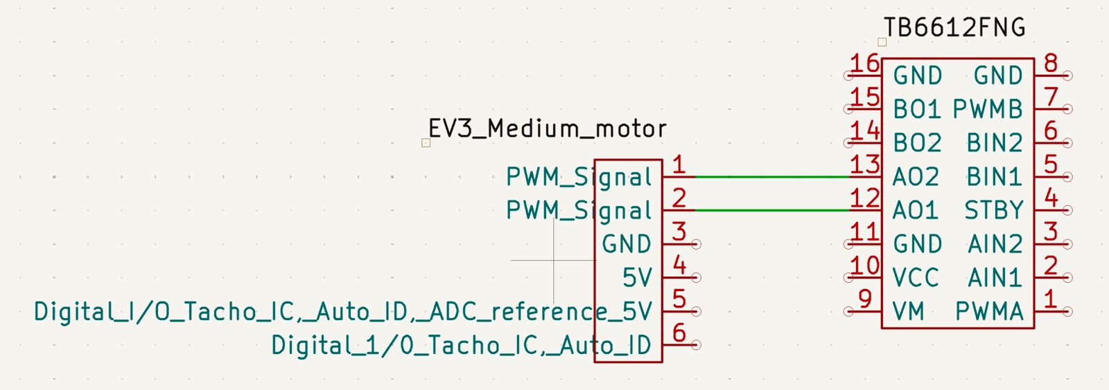
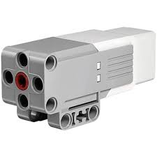
We chose to use a standard LEGO EV3 Medium Motor, as it easily integrates with the lego chassis and lego axle. This motor also embeds an encoder which could be used if required. However, the standard Lego connector doesn’t directly connect to our motor driver, therefore we identified the pinout of the LEGO motor and directly connected the wires to the motor driver. The pinout diagram of Lego EV3 motor is shown below
|
Specifications: |
Potential improvements:
Use the built-in encoder for more accurate movement and turns of the robot. Using the encoder allows for precise and accurate movements, helping in complex tasks like parking.
Consider exploring more powerful non-Lego geared motors that are
-Compact and lightweight
-More powerful
-Cheaper
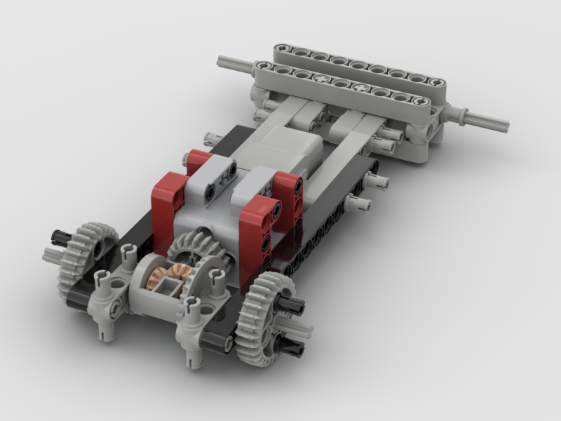
Our EV3 motor is connected to a Lego axle that drives a gear connected to a Lego differential, which splits torque between two wheels. The differential lets both wheels rotate at different speeds when turning, thereby reducing the friction at each wheel, and making turns smoother. We used lego wheels as they are compatible with lego axle used for the chassis. We experimented with a wide variety of Lego wheels for the robot. Increasing the size of the rear wheel increased the robot speed almost linearly proportional to the wheel diameter. Increasing the width of the front tyres caused the robot to skid during turns, hence the front wheels are narrower to make smooth turns. The rear wheels are wider to provide sufficient friction to the vehicle.
Potential Improvements
To control the current received by the motor and to control the speed of the drive motor, we utilized a SparkFun Dual TB6612FNG motor driver. The motor driver is connected to our PCB, and receives signals from the Raspberry Pi.
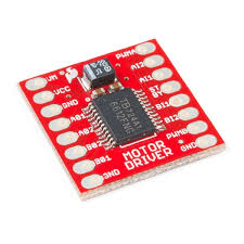
|
Specifications: |
Potential Improvements:
For our steering mechanism, we needed a design that was precise. Like all other aspects of our robot’s design, our first choice was to use a Lego based mechanism. Ackerman steering is a popular choice in automobiles, as the front inner wheel turns more than the front outer wheel, thereby reducing skid. However it was complicated to build it. We first tried the simpler parallel steering mechanism and it turned out to be pretty good for our robot, so we didn't consider Ackerman steering.
The steering could have been driven by any encoder based motor (such as a spike prime small motor) as a makeshift servo motor. The problem was, that while any Lego motor would have been both highly precise and easy to integrate, even the smallest motor was too bulky and required integration with motor driver.
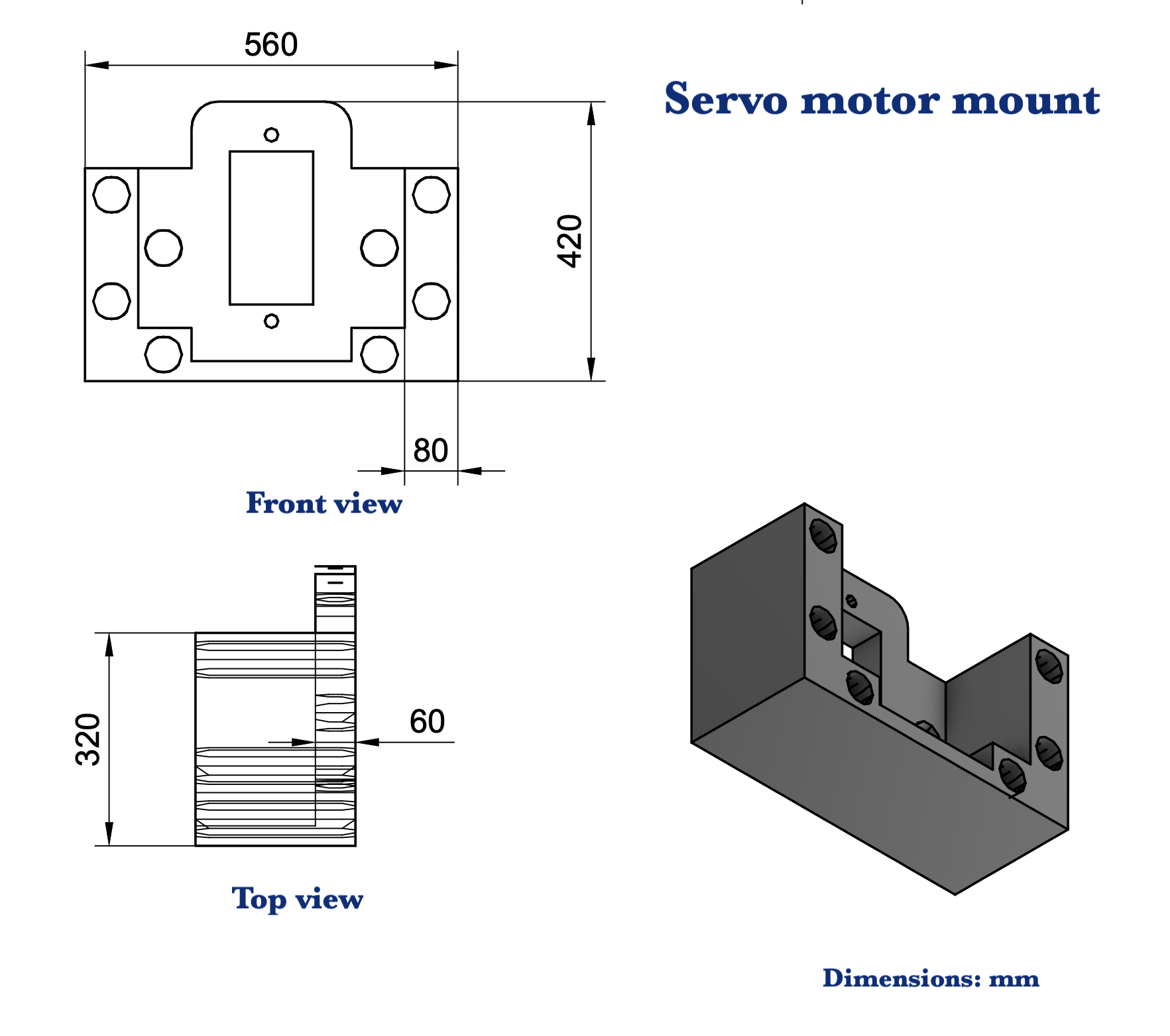
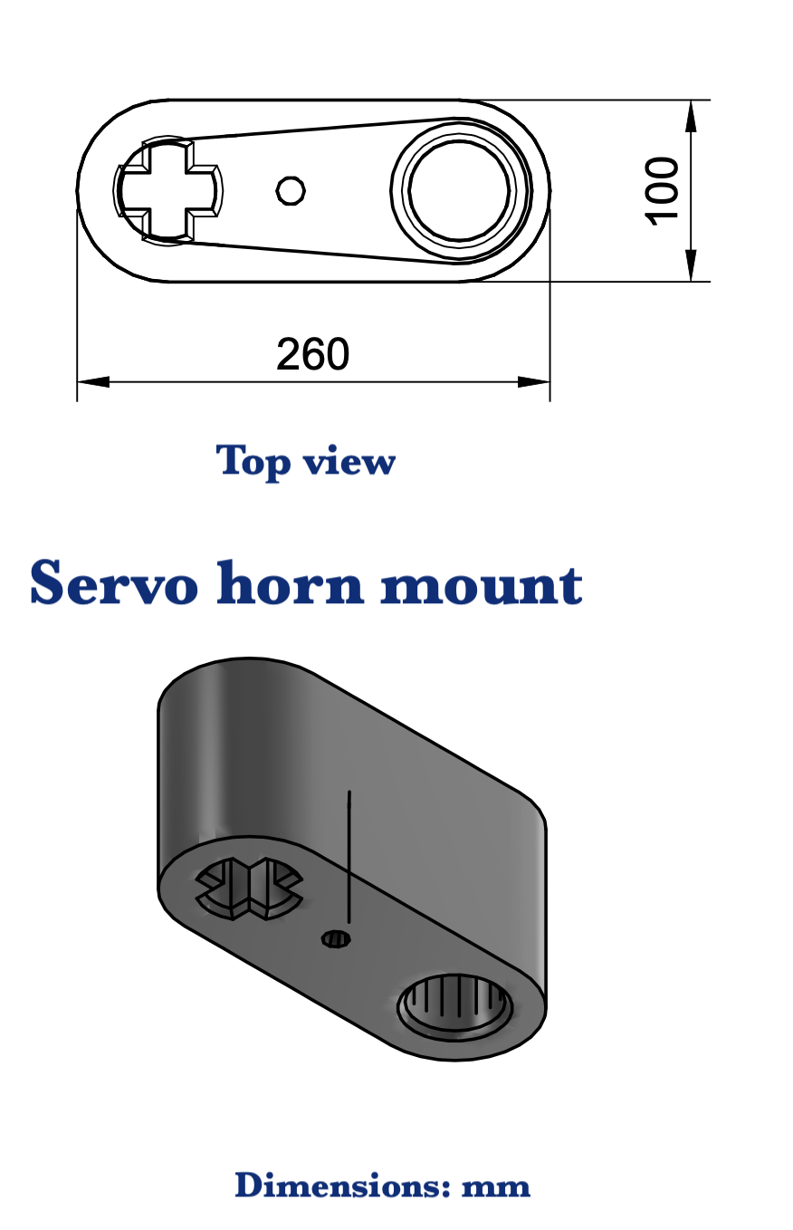
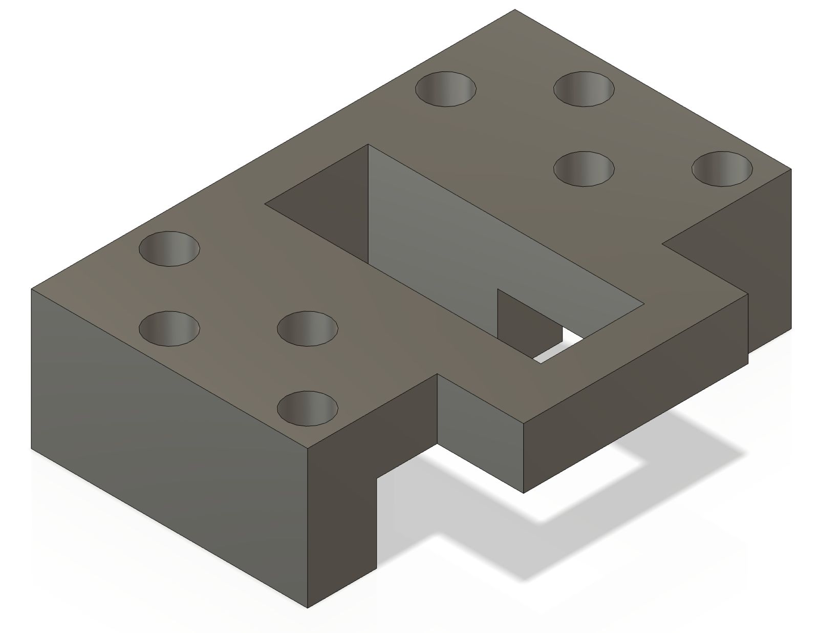
Therefore, we decided to use an off the shelf servo motor, which was not only small but can be driven directly by Raspberry Pi's output port. To integrate it with our Lego based design, we 3D printed a custom servo mount which could be attached with Lego screws to the front of the chassis directly behind the front wheel, while simultaneously hot gluing the servo horn to 3D printed component that couples the horn to the axle of the front wheels.
Potential Improvements:
Our steering system is centered around the SG90 servo motor, which provides precise angular control, making it highly suitable for steering applications where accuracy is essential. Unlike standard DC motors, the SG90 has a built-in feedback mechanism that allows it to hold a commanded angle reliably without additional sensors. Despite its compact size, it delivers sufficient torque to handle the demands of turning the steering mechanism, ensuring stability.
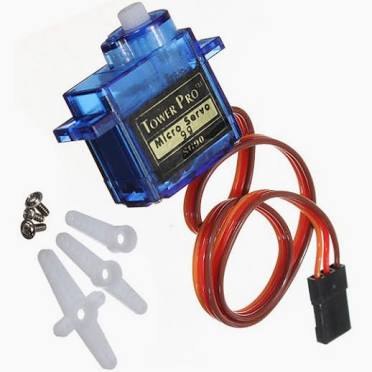
|
Specifications: |
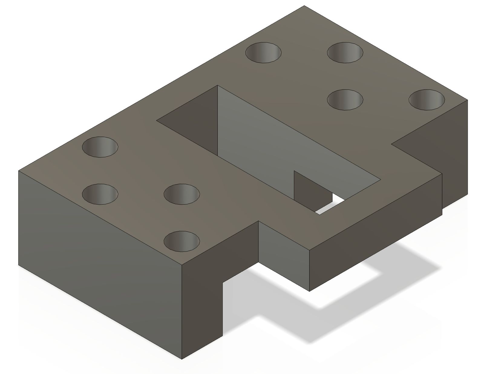
|
Servo mount |
Challenges:
For a brief period, we used an MG90 servo motor instead of our current SG90 motor. An MG90 has metal gears instead of plastic gears, which we believed would make it more reliable. However, the MG90 gears broke in one of our test runs, and we reverted back to the SG90
Potential Improvements:
When starting this project, we realized that the bulk of our effort would go into building autonomous driving software. As we wanted to spend more time on software, and had already spent a considerable amount of time using Lego hardware for our 2024 Robomission challenge, we custom designed the base chassis from elementary Lego parts and rest of the chassis with 3D printed parts.
This approach has many benefits, the primary one being ease of integration. Lego parts can easily be snapped on and off, making chassis development far easier and less time consuming. Making changes to a non-Lego chassis would have meant that each time we wanted to make a change to our chassis, we would have to make new 3D prints, increasing time, cost, waste and materials used.
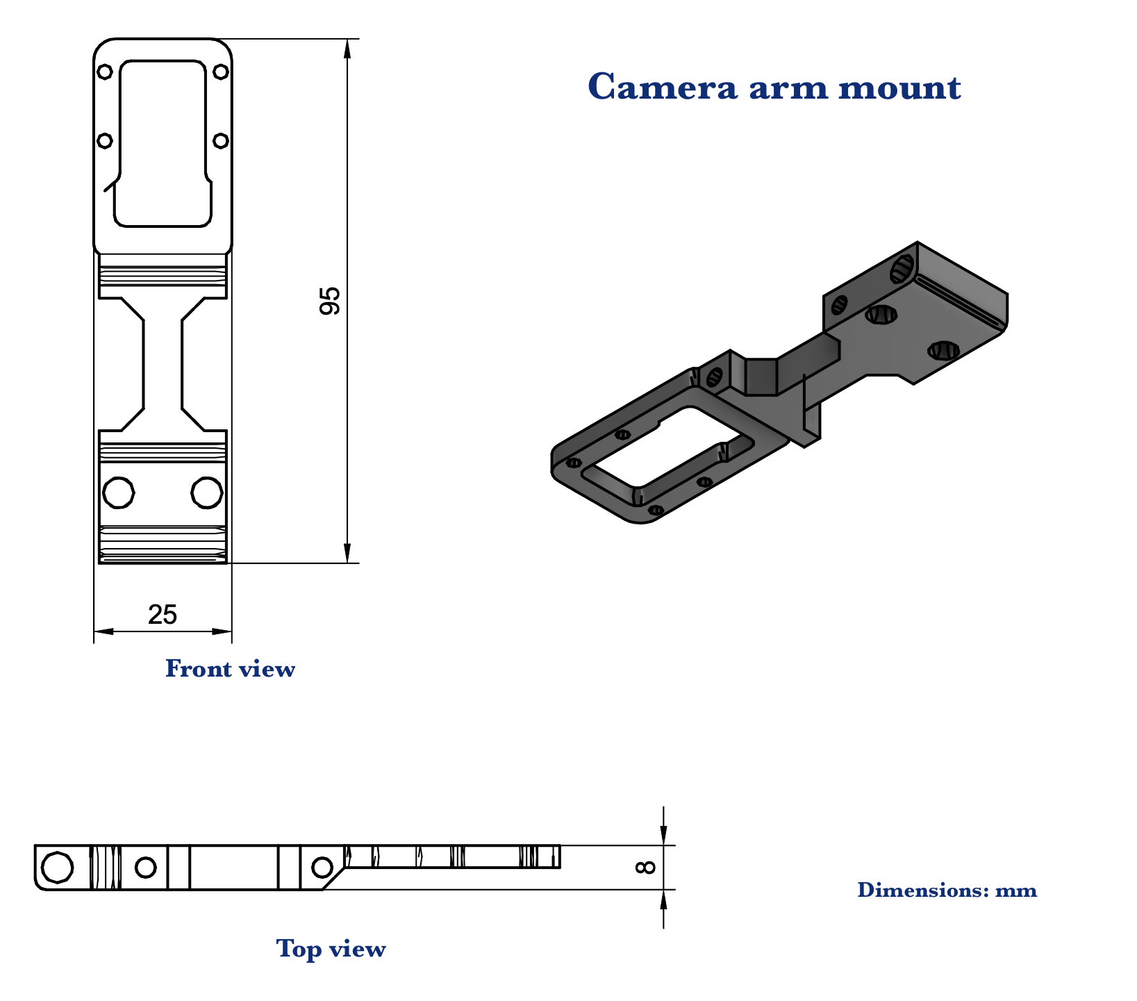
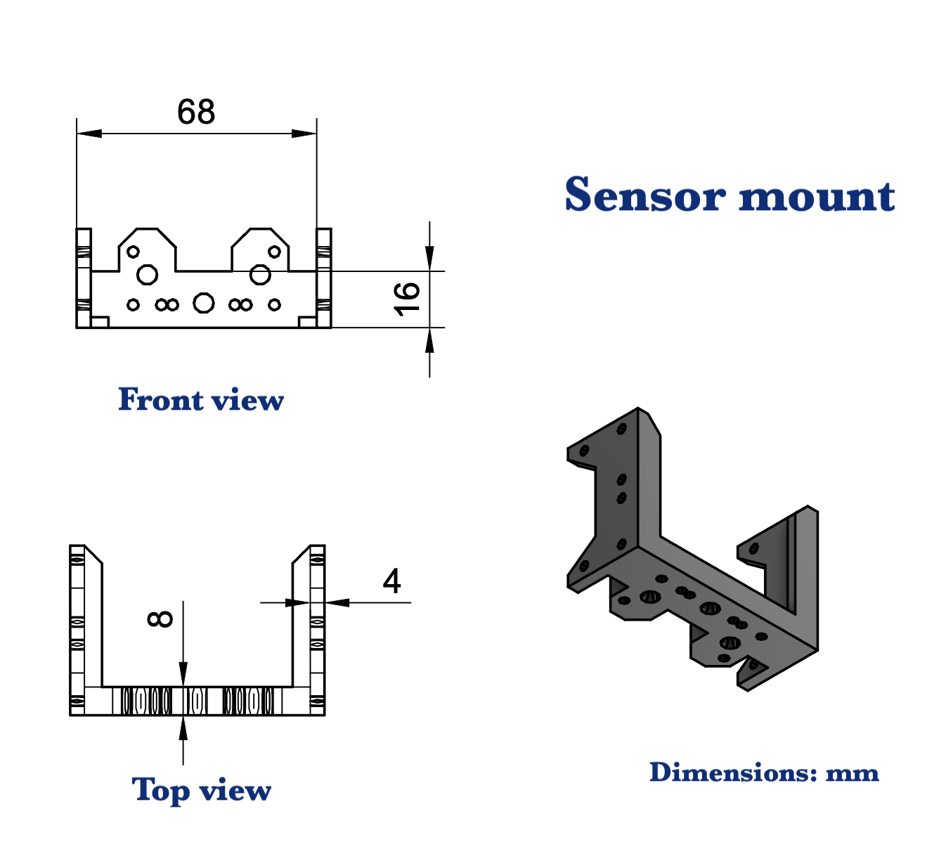
All sensors like the camera, ultrasonic sensors and TOF sensors are attached to the base chassis with 3D printed mounts. This provides robust attachment of the the sensors to the main body. The prototype was built with hot gluing these sensors to the body but this wasn't robust and would come off.
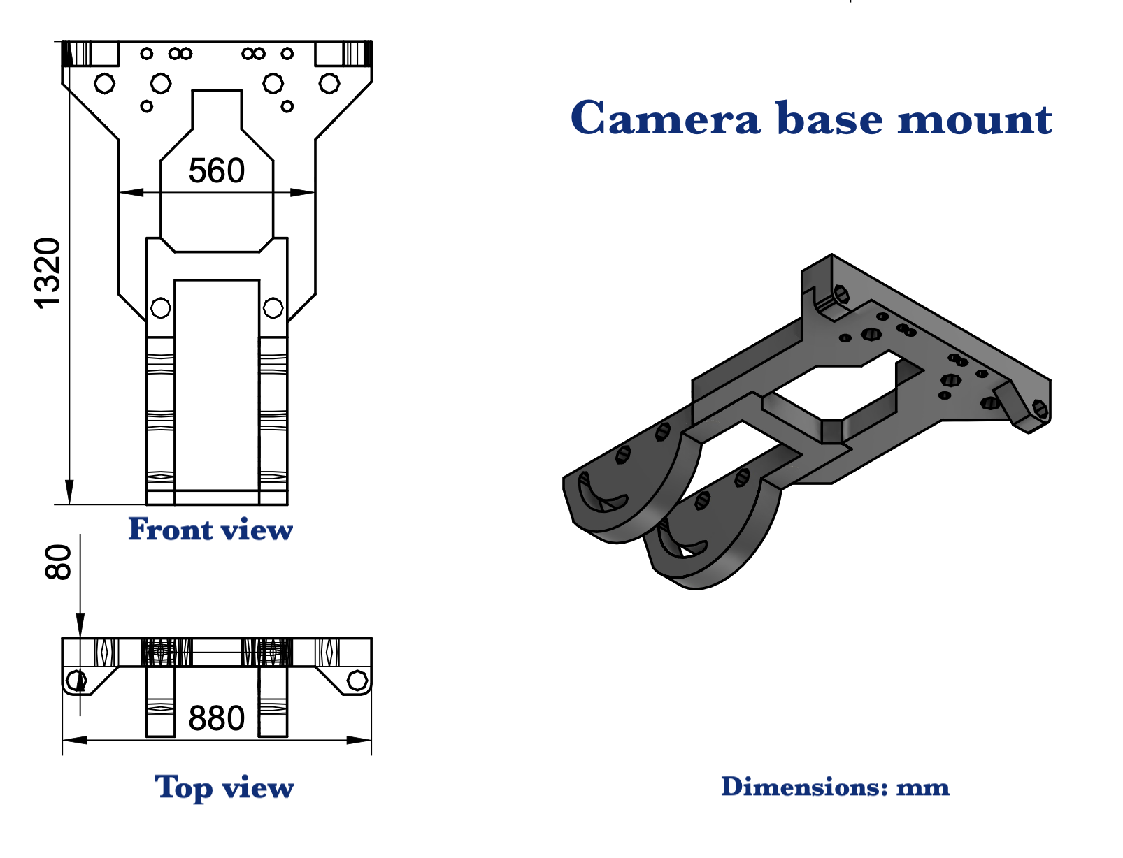 |  |
|---|---|
 |  |
 |
|---|
Potential Improvements:
Controls the drive motor speed and direction using PWM (pulse-width modulation) signals sent to the TB6612FNG motor driver.
def initialize():
    """Initializes the DC motor driver and PWM."""
    global gpio_handle, motor_pwm
    try:
        gpio_handle = lgpio.gpiochip_open(0)
        lgpio.gpio_claim_output(gpio_handle, config.AIN1_PIN)
        lgpio.gpio_claim_output(gpio_handle, config.AIN2_PIN)
        lgpio.gpio_claim_output(gpio_handle, config.STBY_PIN)

        motor_pwm = HardwarePWM(
            pwm_channel=config.MOTOR_PWM_CHANNEL,
            hz=config.MOTOR_PWM_FREQ,
            chip=config.MOTOR_PWM_CHIP,
        )
        motor_pwm.start(0)
        print("INFO: Motor Initialized.")
        return True
    except Exception as err:
        print(f"FATAL: Motor failed to initialize: {err}")
        return False
Explanation: We set up the GPIO pins that control the motor direction (AIN1, AIN2) and standby mode (STBY). We also initialize the PWM signal that controls motor speed.
def forward(speed):
    """Drives the motor forward at a given speed."""
    if gpio_handle:
        lgpio.gpio_write(gpio_handle, config.STBY_PIN, 1)  # Enable motor
        lgpio.gpio_write(gpio_handle, config.AIN1_PIN, 1)  # Forward direction
        lgpio.gpio_write(gpio_handle, config.AIN2_PIN, 0)
        _set_speed(speed)  # Set speed 0-100

def reverse(speed):
    """Drives the motor in reverse at a given speed."""
    if gpio_handle:
        lgpio.gpio_write(gpio_handle, config.STBY_PIN, 1)  # Enable motor
        lgpio.gpio_write(gpio_handle, config.AIN1_PIN, 0)  # Reverse direction
        lgpio.gpio_write(gpio_handle, config.AIN2_PIN, 1)
        _set_speed(speed)

def brake():
    """Brakes the motor by shorting its terminals."""
    if gpio_handle:
        lgpio.gpio_write(gpio_handle, config.STBY_PIN, 1)
        lgpio.gpio_write(gpio_handle, config.AIN1_PIN, 1)  # Both pins high = brake
        lgpio.gpio_write(gpio_handle, config.AIN2_PIN, 1)
        _set_speed(0)
Explanation: These functions control motor direction by setting the AIN1 and AIN2 pins. Forward sets AIN1=1 and AIN2=0. Reverse does the opposite. Brake sets both to 1, which stops the motor quickly.
Controls the steering servo angle using PWM signals. The servo position determines the steering direction.
def initialize():
    """Initializes the servo motor PWM."""
    global servo_pwm

    for attempt in range(1, 6):  # Try up to 5 times
        try:
            servo_pwm = HardwarePWM(
                pwm_channel=config.SERVO_PWM_CHANNEL,
                hz=config.SERVO_PWM_FREQ,
                chip=config.SERVO_PWM_CHIP,
            )
            servo_pwm.start(0)
            set_angle(0.0)  # Center the servo
            time.sleep(0.5)
            print("INFO: Servo Initialized.")
            return True
        except PermissionError as err:
            print(f"WARNING: Servo PWM permission denied (attempt {attempt}/5): {err}")
            time.sleep(0.1 * attempt)

    print("FATAL: Servo failed to initialize after 5 attempts")
    return False
Explanation: We initialize the PWM signal for the servo. The servo needs a specific frequency (50 Hz) and pulse width to set its angle. We center it at 0 degrees during startup.
def set_angle(input_angle: float):
    """Sets the servo to a specific angle (-45 to +45 degrees)."""
    if servo_pwm is None:
        return

    # Clamp angle to safe limits
    clamped_angle = max(-45, min(45, input_angle))

    # Convert angle to PWM duty cycle
    # Servo expects 1-2ms pulse width at 50Hz frequency
    pulse_width_ms = 1.5 + (clamped_angle / 90) * 0.5
    duty_cycle = (pulse_width_ms / 20) * 100

    servo_pwm.change_duty_cycle(duty_cycle)
Explanation: Servo motors work by receiving a PWM signal with a specific pulse width. A 1.5ms pulse = center (0°), 1ms = full left (-90°), 2ms = full right (+90°). We calculate the duty cycle based on the desired angle.
Our robot uses a Raspberry Pi 5 to process data from several sensors. We use ultrasonic and TOF sensors for distance, an IMU for orientation, and a camera for autonomous driving. A Li-Po battery powers the entire system.
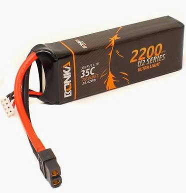
Our robot uses a Bonka 11.1V 2200mAh LiPo battery, commonly found in drones and quadcopters. We chose this battery because its compact form factor fits in the narrow space beneath the chassis. Mounting the heavy battery low in the robot lowers the center of mass, which improves stability.
|
Specifications: |
Potential Improvements
Implement a battery level indicator
Explore if a Lithium-Ion battery is available in the required form factor, as it
Is safer
Has more charge cycles
Doesn't require a complex charger that a LiPo requires
Can be easily removed and replaced with another charged battery
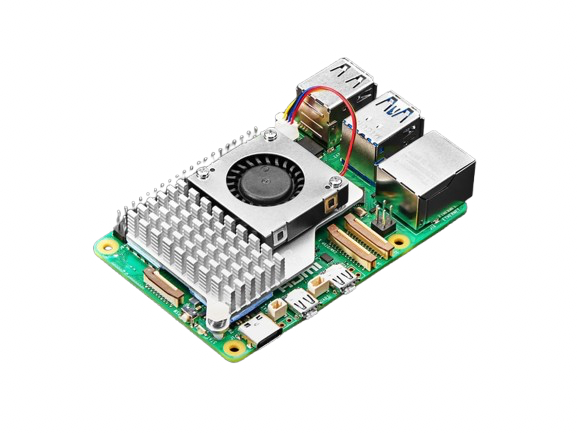
The heart of our robot is the Raspberry Pi 5 microcomputer. It processes inputs from our distance sensors, runs image processing algorithms on the live camera feed and controls the motors to drive the robot to achieve its desired goals.
We chose this particular model as it seamlessly integrates with a camera, making it easier to use than similar computers or microcontrollers such as an Arduino or ESP32. Additionally, we also wanted to take advantage of the Raspberry Pi 5 being far more powerful than other processors, allowing us to use newer and improved image processing technologies that deliver more accurate results but may require greater computing power.
Potential Improvements
|
Specifications: |
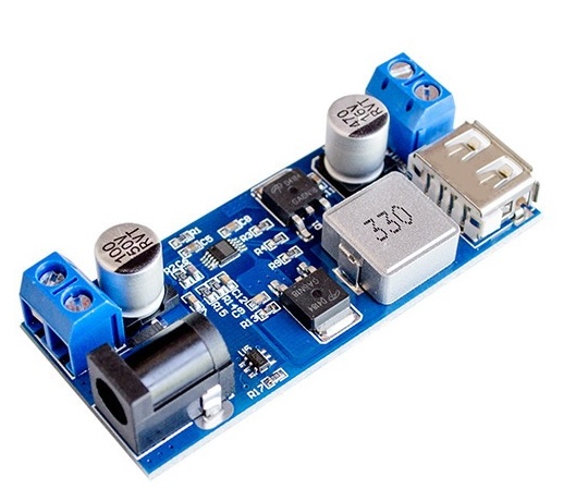
Our battery provides 12V, but our Raspberry Pi requires 5V and our motor requires 9V. To supply these lower voltages safely, we used a XY-3606 step-down (buck) voltage converter.
Potential Improvements
|
Specifications: |
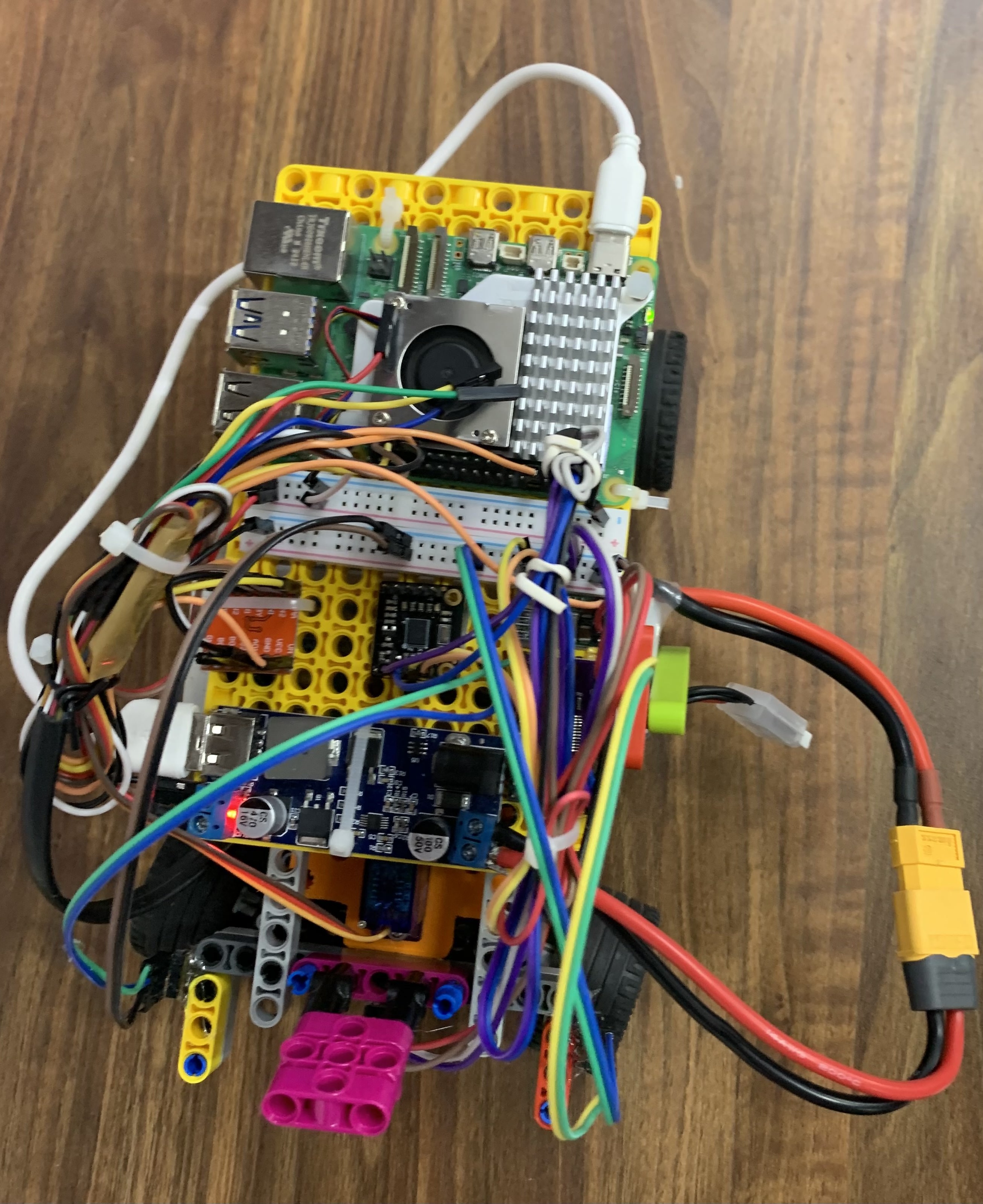
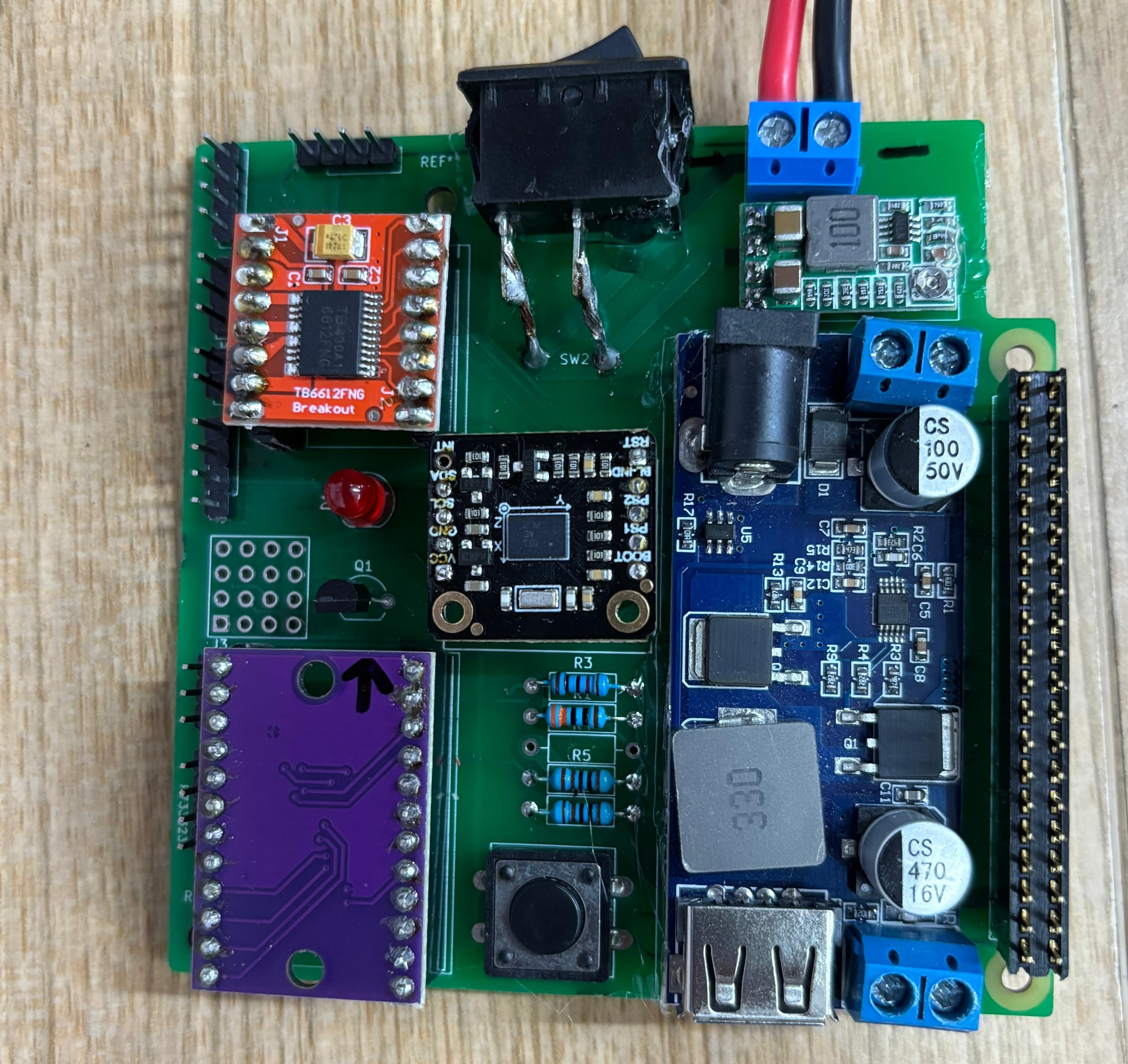
In our first draft of the robot, there were many criss-crossing wires between many different components. A lack of clean arrangement for the wires made the robot very messy to handle. During practice runs, wires would routinely get loose, making it difficult to troubleshoot errors.
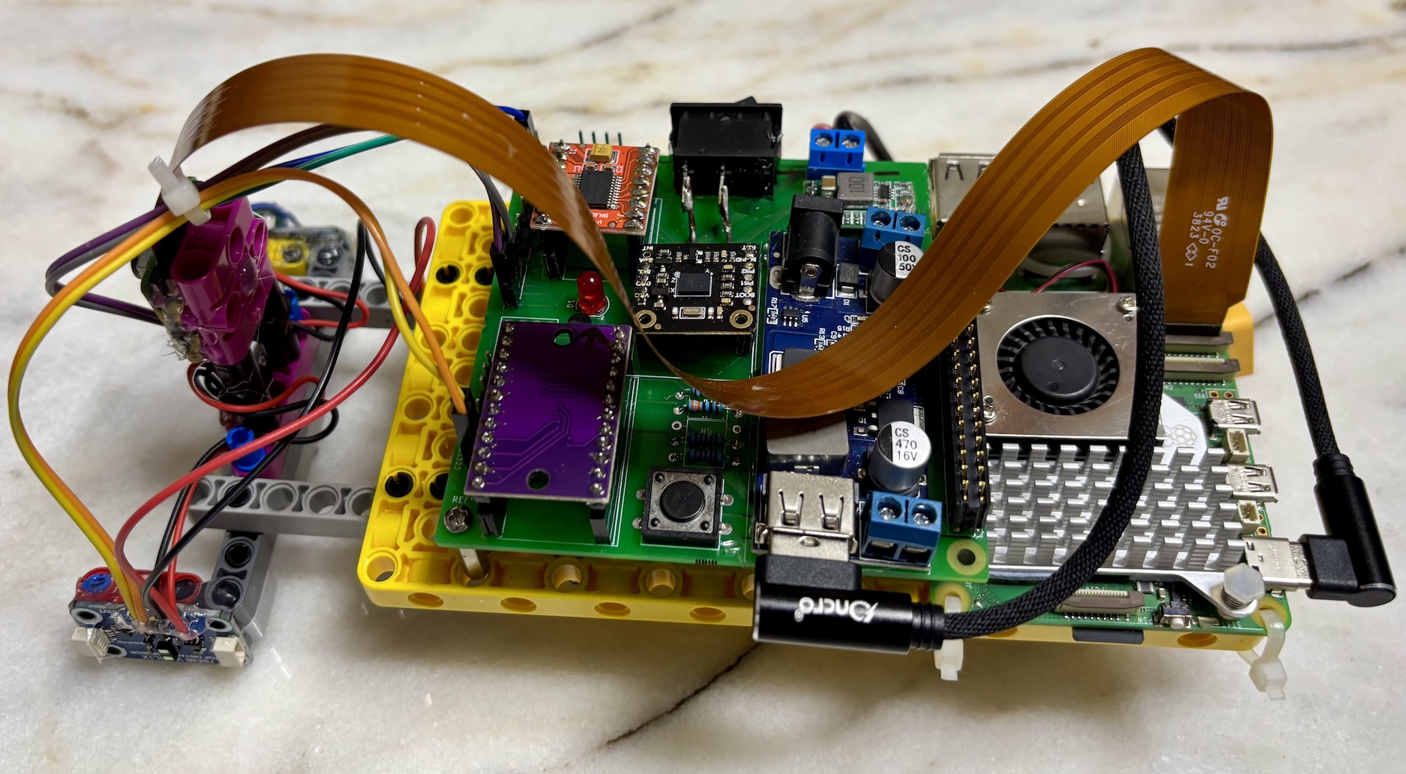
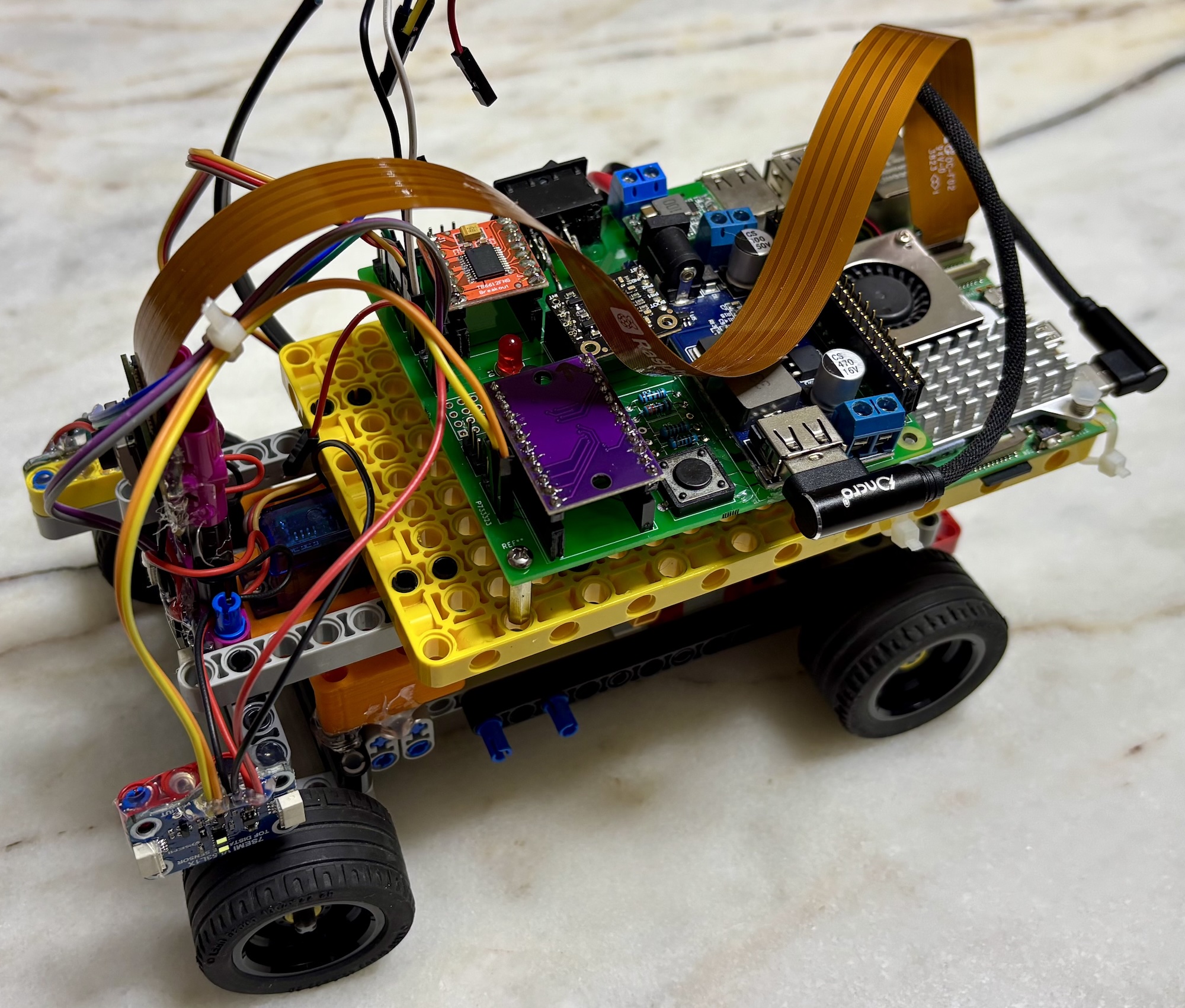
To solve this, we designed a PCB which cleanly connected all of our components together, making the robot far cleaner and reliable.
Here is a comparison showing our robot before and after the PCB
| Before | After |
|---|---|
 | |
|
PCB |
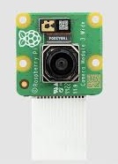
For image detection, we are using the Raspberry Pi Camera Module 3. This uses a CMOS sensor, the Sony IMX708. Apart from its ease of integration with the Raspberry Pi, the Camera module 3 has autofocus, wide-angle and low-light performance, all of which are very useful in a competition setting.
We explored few other alternatives as well. The Raspberry Pi AI camera provides built in detection for many objects, but has a limited Field Of View which didn't work for our requirements. The Raspberry Pi HQ camera though bulky comes with a standard CS mount that allowed us to mount different fish eye lenses. A fish eye lens camera provides a much larger Field Of View (160° - 180°) even when mounted in the front on a straight mount at 10cm height. This allows us to cut off the field view above the black walls making the robot resilient to off field objects. However the image is distorted towards the edges and tuning the robot to detect objects proved difficult for us.
|
Specifications: |
Potential Improvements
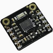
Our robot uses the BNO055 IMU (Inertial Measurement Unit) to help it maintain direction when moving straight, and to make turns more accurate. The BNO055 combines data from an accelerometer, gyroscope, and magnetometer to provide absolute orientation, which reduces drift and allows the robot to correct its heading in real time.
|
Specifications: |
Potential Improvements
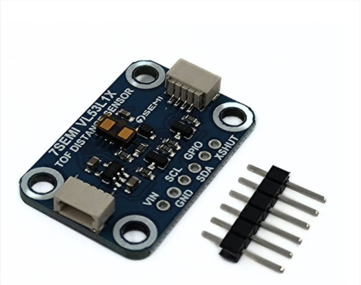
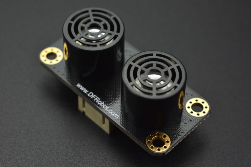
Apart from the camera, our robot uses TOF based distance sensors VL53L1X / VL53L8CX and URM09 Ultrasonic sensor to gather inputs. The sensors are mounted on the front, back, left, and right of the robot respectively. The front and back sensors are used to avoid hitting the parking walls. The left and right sensors are used to detect the starting direction for obstacle challenge. They could potentially be used for a surprise rule that may be announced at the competition.
Reasons for using different sensors
|
VL53L1X Specifications: |
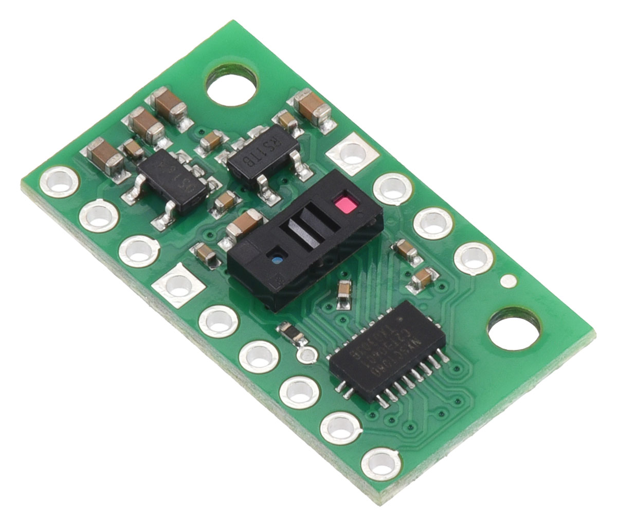
|
VL53L8CX Specifications: |
|
URM09 Specifications: |
Alternatives considered
Along with the Ultrasonic and VL53L1X sensors, we also considered LiDAR sensors to help map the game field. In the end, though, we decided to pass on this, as LiDAR sensors are too expensive. Adding a single LiDAR sensor could have increased the robot's cost by nearly 40%. Additionally, at the short ranges relevant to this game field, our existing ultrasonic and ToF sensors already provide sufficient accuracy, so LiDAR would not have meaningfully improved the robot’s accuracy.
Potential Improvements
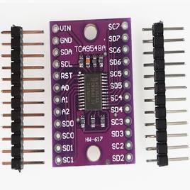
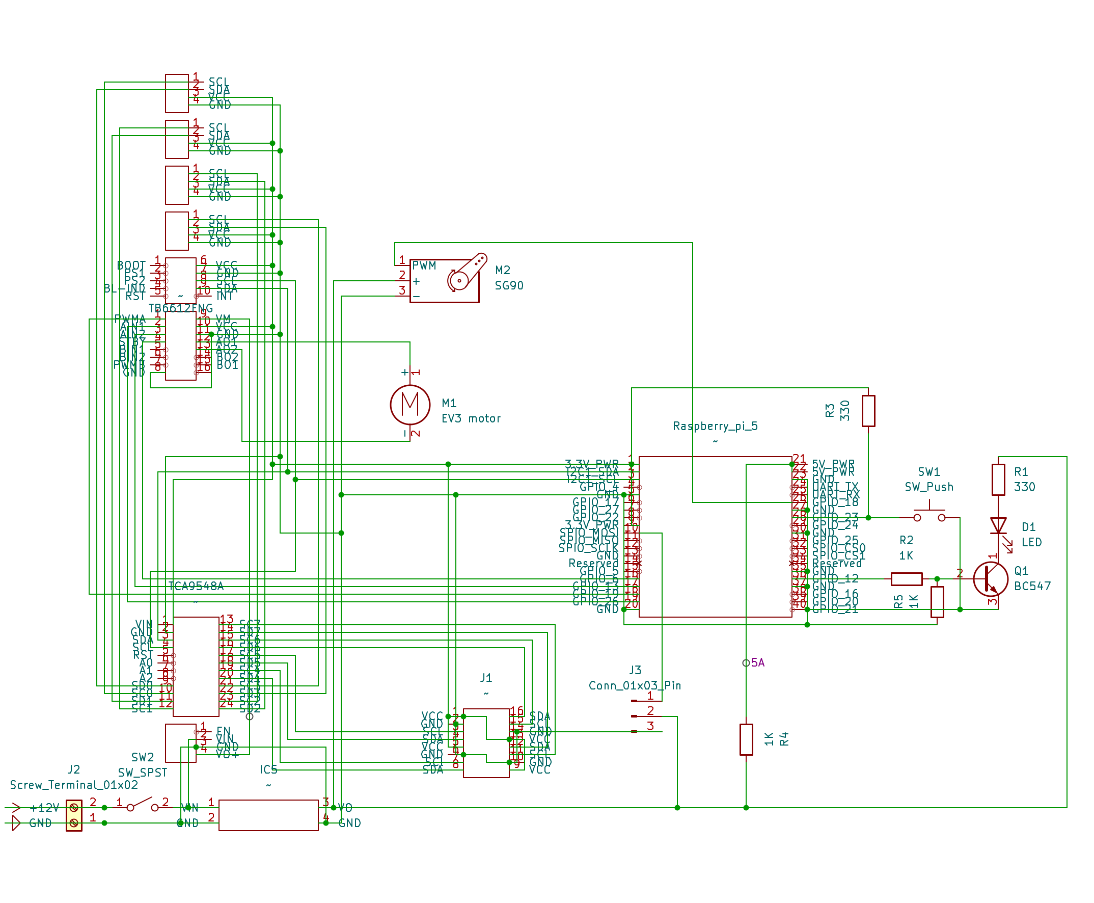
All four of our distance sensors share the same I²C address. Our CJMCU TCA9548A multiplexer splits the distance sensors into separate channels so only one device is active at a time. This gives each device a “virtual” unique address, letting them coexist without conflict.
|
Specifications: |
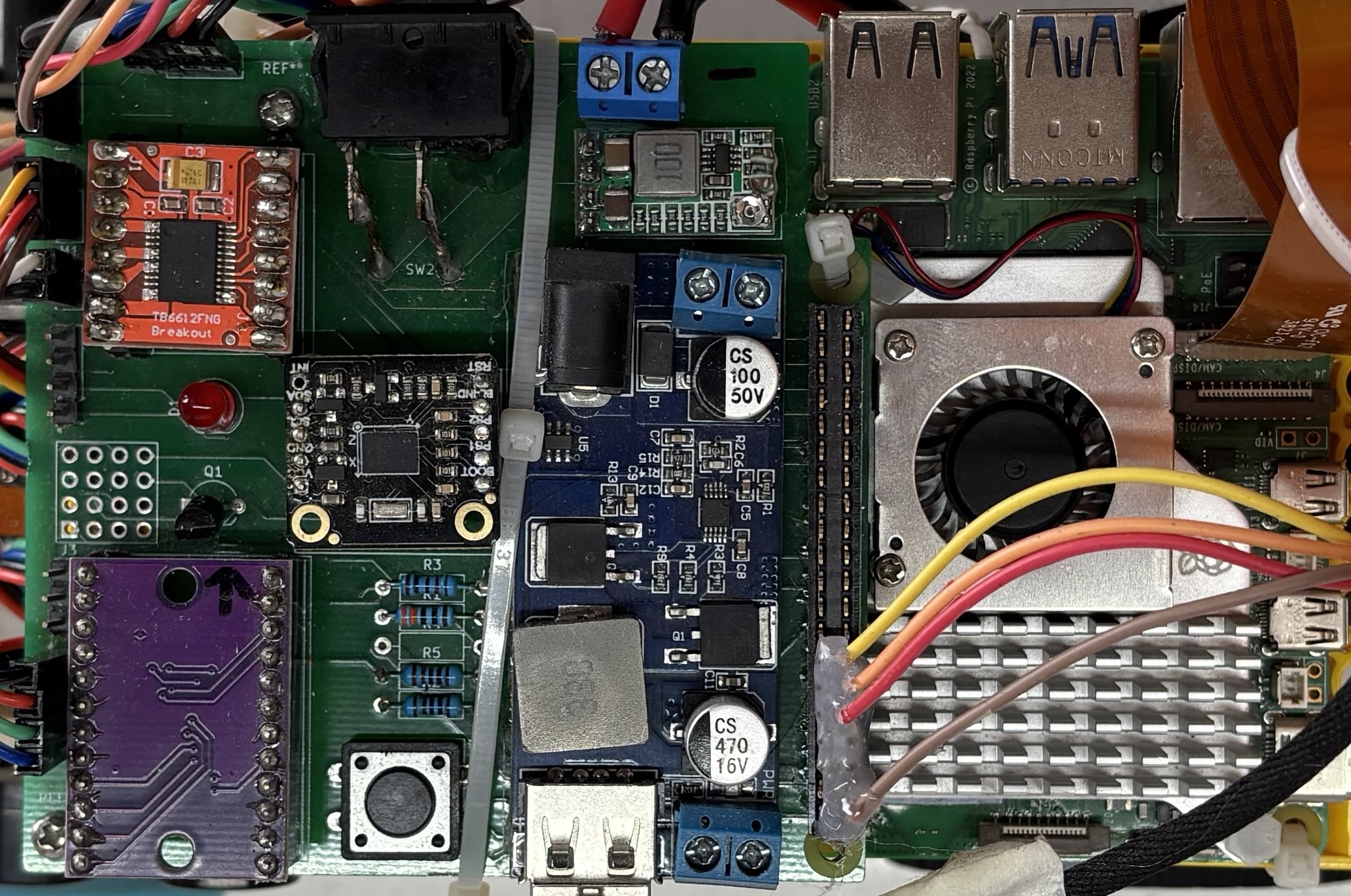
A full wiring diagram is shown in the screenshot below, and available at models/PCB/~Untitled.kicad_sch
Measures the robot's heading (direction) using a combination of gyroscope, accelerometer, and magnetometer sensors.
def initialize():
    """Initializes the BNO055 sensor."""
    global sensor

    try:
        i2c = board.I2C()
        sensor = adafruit_bno055.BNO055_I2C(i2c)
        sensor.mode = adafruit_bno055.NDOF_MODE  # 9-DOF mode
        time.sleep(1)  # Let sensor boot up

        print(f"INFO: Gyro (BNO055) Initialized. Temp: {sensor.temperature}°C")
        print(f"INFO: Calibration status: {sensor.calibration_status}")
        return True
    except Exception as e:
        print(f"WARNING: Gyro disabled. Could not initialize: {e}")
        sensor = None
        return True
Explanation: We initialize the BNO055 on the I2C bus and set it to NDOF mode (9-Degree of Freedom), which uses all three sensors together for accurate heading measurement.
def get_heading():
    """Returns the current heading (yaw) in degrees."""
    if sensor:
        try:
            heading, _, _ = sensor.euler  # Get yaw (heading) from Euler angles
            if heading is not None:
                return heading
        except Exception:
            return None
    return None

def get_initial_heading(num_readings=20):
    """Gets an averaged, stable initial heading."""
    if not sensor:
        return 0.0

    print("INFO: Acquiring initial heading...")
    readings = []
    for _ in range(num_readings):
        yaw = get_heading()
        if yaw is not None:
            readings.append(yaw)
        time.sleep(0.05)
Explanation: The BNO055 returns Euler angles (heading, roll, pitch). We extract the heading (yaw) which tells us which direction the robot is facing. We average multiple readings at startup to get a stable initial heading.
Captures video frames for obstacle detection and color identification using computer vision.
def initialize():
    """Initializes the Picamera2."""
    global picam2
    try:
        picam2 = Picamera2()
        cam_config = picam2.create_preview_configuration(
            main={
                "format": "RGB888",
                "size": (2304, 1296),  # High resolution for processing
            },
            lores={
                "size": (640, 360),    # Low resolution for fast processing
                "format": "RGB888"
            },
            controls={
                "ExposureTime": 8000,  # Exposure time in microseconds
                "FrameRate": 56,       # Frames per second
            }
        )
        picam2.configure(cam_config)
        picam2.start()
        time.sleep(1.0)
        print("INFO: Camera Initialized.")
return TrueExplanation: We set up the camera with two resolutions: high resolution (2304×1296) for detailed processing and low resolution (640×360) for fast real-time processing. We also set exposure time and frame rate for consistent image quality.
def capture_frame():
    """Captures and returns a single frame from the camera."""
    if picam2:
        frame = picam2.capture_array("lores")  # Get low-res frame for speed
        return frame
    return None
Explanation: We capture frames from the low-resolution stream for fast processing. This lets us run obstacle detection at 30 FPS without slowing down the robot.
Measures distance to walls and obstacles using time-of-flight (ToF) technology. Four sensors are mounted on the front, back, left, and right.
def initialise():
    """Initializes the I2C bus, multiplexer, and all distance sensors."""
    global _i2c_main, _mux, _sensors, _sensor_types

    try:
        _i2c_main = busio.I2C(board.SCL, board.SDA)
    except Exception as e:
        print(f"FATAL: Could not initialize I2C bus. Error: {e}")
        return False

    try:
        _mux = adafruit_tca9548a.TCA9548A(_i2c_main, address=0x70)
        print("INFO: TCA9548A Mux found at address 0x70.")
    except ValueError:
        print("WARNING: TCA9548A Mux not found.")
        _mux = None

    # Probe each channel for sensors
    if _mux:
        print("INFO: Probing for sensors on mux channels...")
        for i in range(8):
            channel_bus = _mux[i]

try:Explanation: We initialize the I2C bus and the TCA9548A multiplexer. The multiplexer lets us connect 4 sensors with the same I2C address by switching between channels. We probe each channel and initialize any VL53L1X sensors we find.
def get_distance(channel):
    """Reads the distance from a sensor on a specific channel."""
    if channel not in _sensors:
        return None

    sensor = _sensors[channel]

    try:
        if sensor.data_ready:  # Check if new data is available
            distance_cm = sensor.distance
            sensor.clear_interrupt()
            return distance_cm * 10.0 if distance_cm is not None else None
        return None  # No new data yet
    except (OSError, IOError):
        print(f"I/O Error on channel {channel}. Sensor may be disconnected.")
        return None
Explanation: We check if the sensor has new data ready. If it does, we read the distance in centimeters and convert it to millimeters. If no new data is ready, we return None immediately without blocking.
Navigate 3 laps using camera-based wall detection steering straight in the straight sections. Steer according to the driving section in the corner section. Count turns using orange lines. Stop after 12 turns.

left_pixel_size = sum(obj['area'] for obj in detected_walls if 'left' in obj['type'])
right_pixel_size = sum(obj['area'] for obj in detected_walls if 'right' in obj['type'])

# If one side wall disappears, turn sharply towards the other side
if left_pixel_size < 100 and right_pixel_size > 100:
    right_pixel_size += 25000
elif right_pixel_size < 100 and left_pixel_size > 100:
    left_pixel_size += 25000

angle = ((left_pixel_size - right_pixel_size) * 0.0005)orange_detection_history = deque([False] * 4, maxlen=4)
cooldown_frames = 0
orange_detected_this_frame = bool(detections['detected_orange'])
orange_detection_history.append(orange_detected_this_frame)
if cooldown_frames > 0:
cooldown_frames -= 1
elif not orange_detection_history[-4] and all(list(orange_detection_history)[1:]):
turn_counter += 1
cooldown_frames = 50close_black_area = sum(obj['area'] for obj in detections.get('detected_close_black', []))
if close_black_area > 3000:
if left_pixel_size < right_pixel_size:
angle = -35
else:
angle = 35Navigate 3 laps while avoiding colored blocks. Drive left of the green block and right of the red block. Detect the driving direction automatically. Count turns using orange lines. Avoid the magenta parking blocks in all laps. Execute parallel parking just before the vehicle approaches the 13th orange line.
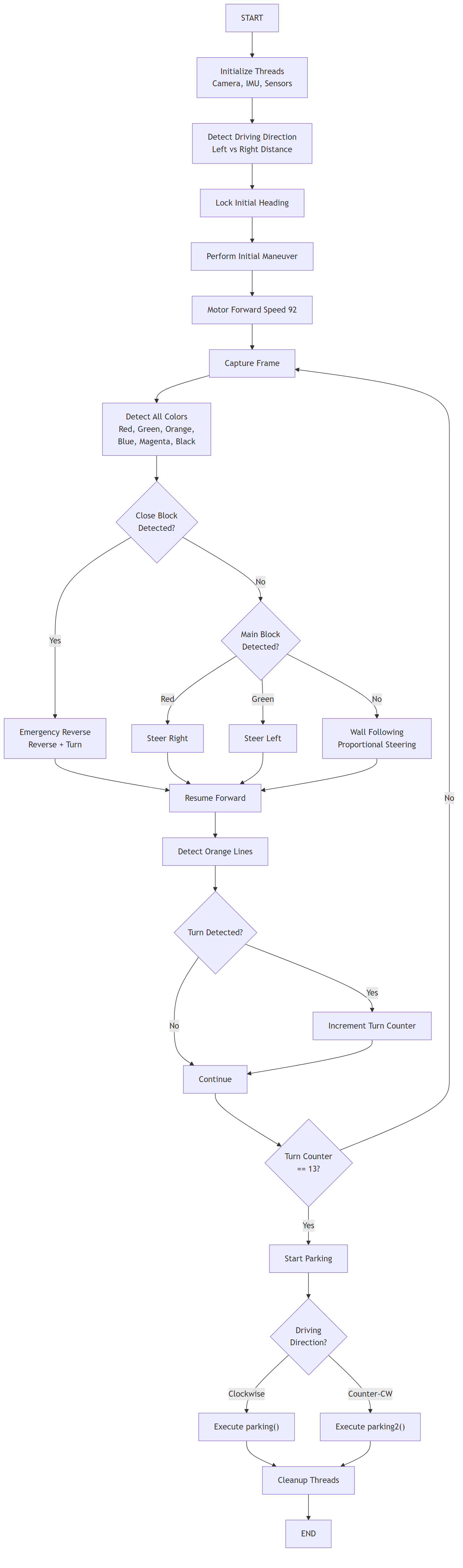
dist_left = sensor_thread.get_readings()['distance_left']
dist_right = sensor_thread.get_readings()['distance_right']

if dist_left is not None and dist_right is not None:
    if dist_left < dist_right:
        driving_direction = "clockwise"
    else:
driving_direction = "counter-clockwise"This is the logic for counter clockwise. The logic for clockwise would be mirrored
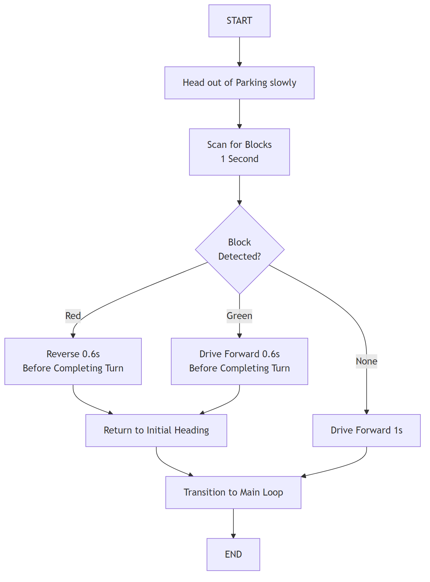
SCAN_TRIGGER_ANGLE_DEG = 25.0
TOTAL_TURN_ANGLE_DEG = 85.0

motor.forward(MANEUVER_SPEED)
servo.set_angle_unlimited(initial_turn_servo)

while get_angular_difference((INITIAL_HEADING+SCAN_TRIGGER_ANGLE_DEG)%360,
                             imu_thread.get_heading()) > 10:
    time.sleep(0.01)

motor.brake()
# Scan for blocks
detected_block_color = None
scan_start_time = time.monotonic()

while time.monotonic() - scan_start_time < 1.0:
    frame, frame_counter = camera_thread.get_frame()
    if frame is None: continue
    detections = process_video_frame(frame)
    main_blocks = [b for b in detections.get('detected_blocks', []) if b['type'] == 'block']

    if main_blocks and main_blocks[0]['area'] > 1000:
        detected_block_color = main_blocks[0]['color']
breakDetect 6 different colors to identify walls, blocks, turn lines, and parking boundaries. Each color serves a specific purpose in navigation and obstacle avoidance.
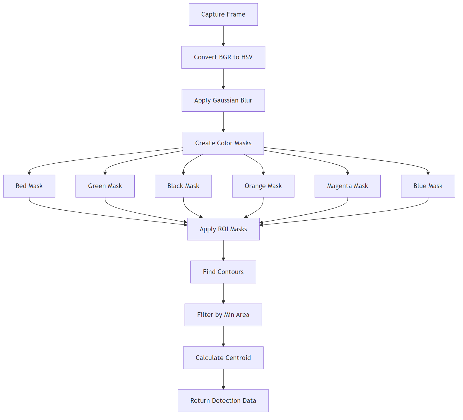
def process_video_frame(frame):
    hsv_frame = cv2.cvtColor(frame, cv2.COLOR_BGR2HSV)

    mask_red1 = cv2.inRange(hsv_frame, [0, 150, 80], [10, 255, 255])
    mask_red2 = cv2.inRange(hsv_frame, [175, 150, 80], [180, 255, 255])
    mask_red = cv2.bitwise_or(mask_red1, mask_red2)

    mask_green = cv2.inRange(hsv_frame, [36, 50, 70], [89, 255, 255])
    mask_orange = cv2.inRange(hsv_frame, [6, 70, 20], [26, 255, 255])
    mask_magenta = cv2.inRange(hsv_frame, [158, 73, 64], [173, 255, 223])
    mask_blue = cv2.inRange(hsv_frame, [94, 45, 58], [140, 226, 185])

    # Apply ROI masks and find contours
# ... contour detection logicWhy multiple ROIs?
Detect colored blocks (red and green) and execute appropriate maneuvers to avoid them. Handle both emergency situations (very close blocks) and normal avoidance (blocks ahead).
Close Blocks (Emergency Reverse):
Main Blocks (Steering Avoidance):
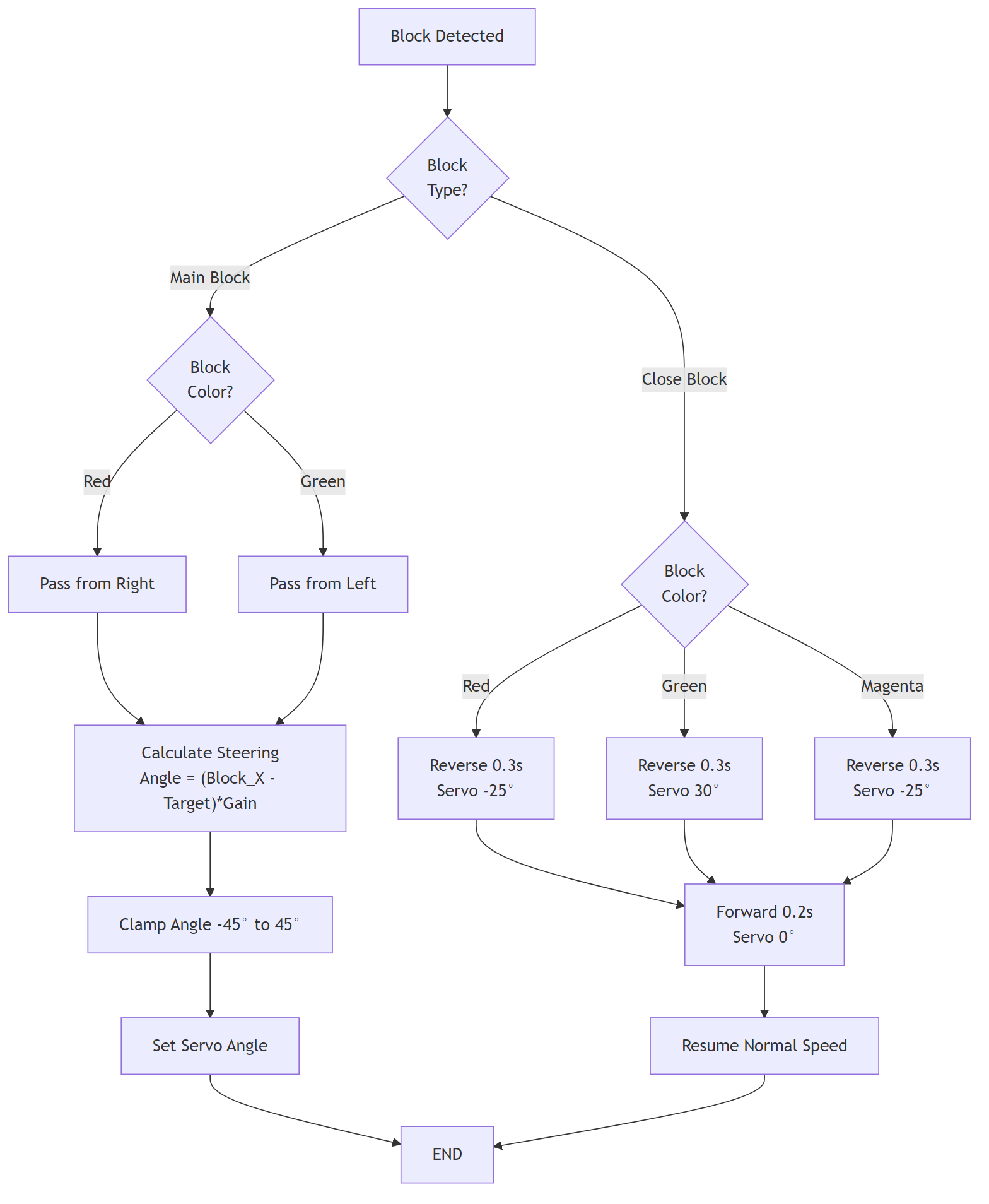
if detected_blocks:
    is_close_block = False
    for block in detected_blocks:
        if block['type'] == 'close_block':
            is_close_block = True
            if block['color'] == 'red':
                angle = -25
            elif block['color'] == 'green':
                angle = 30
            servo.set_angle(angle)
            motor.reverse(60)
            time.sleep(0.5)
            motor.forward(60)
            servo.set_angle(-angle)
            time.sleep(0.3)
            motor.forward(MOTOR_SPEED)
            break

    if not is_close_block:
        block = detected_blocks[0]
        block_color = block['color']
        block_x, block_y = block['centroid']

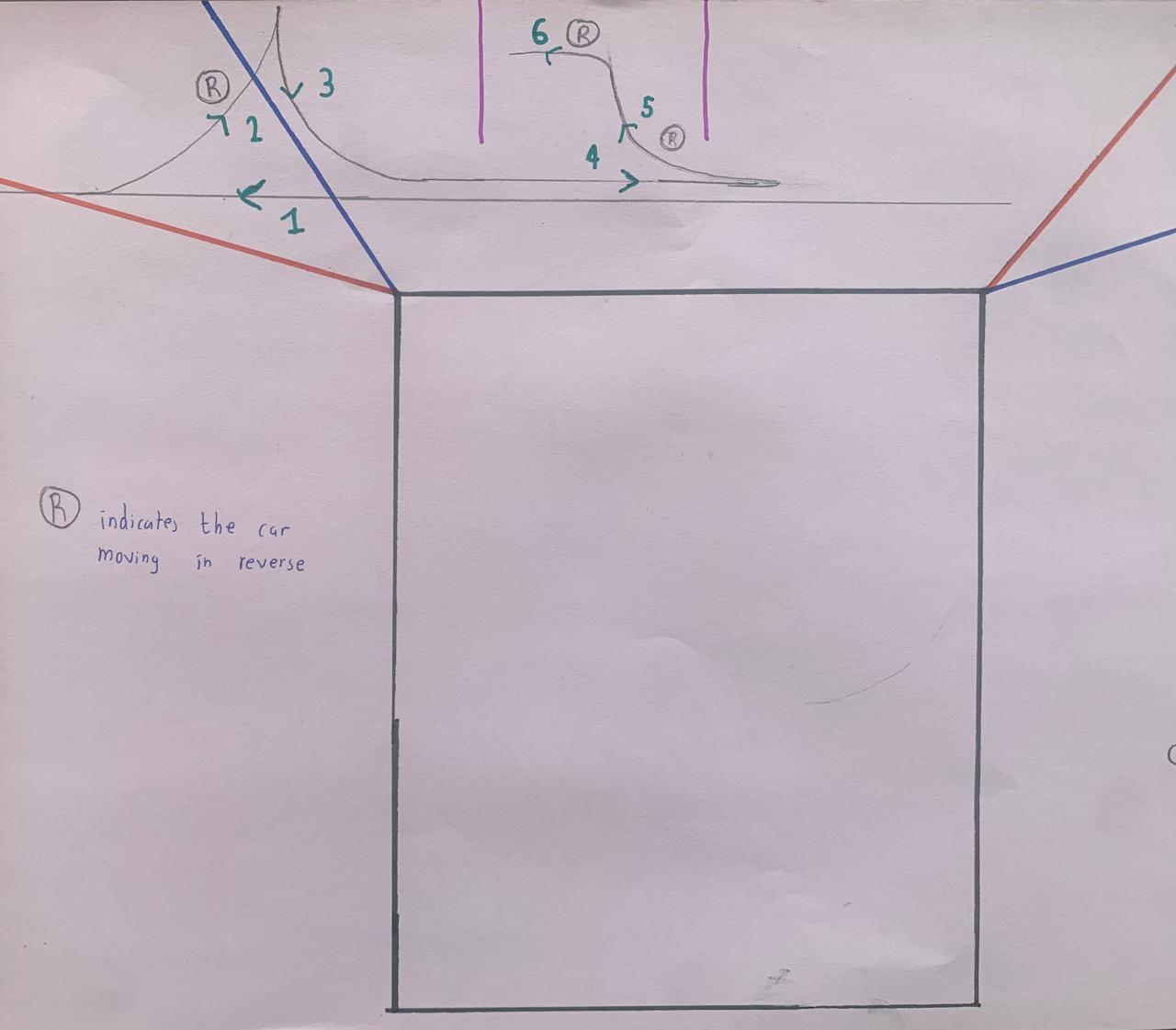
if block_color == 'red':Execute parallel parking maneuver in two directions (clockwise and counter-clockwise). Use wall following and magenta block detection to position robot precisely at the parking start point. Then execute a parking maneuver to park parallely between parking boundaries.
Threading allows the robot to process multiple tasks simultaneously:
CameraThread:
ImuThread:
SensorThread:
VideoWriterThread:
Use locks (mutexes) to prevent simultaneous access to shared data. Only one thread can access data at a time.
We started building the robot in mid of January 2025 and here is a timeline of our robot evolution over the last 10 months!
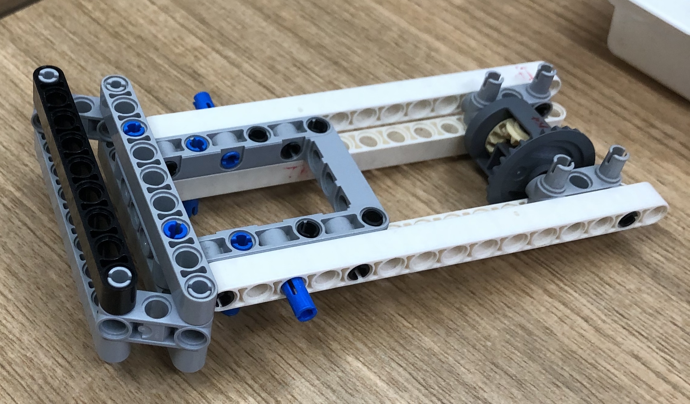
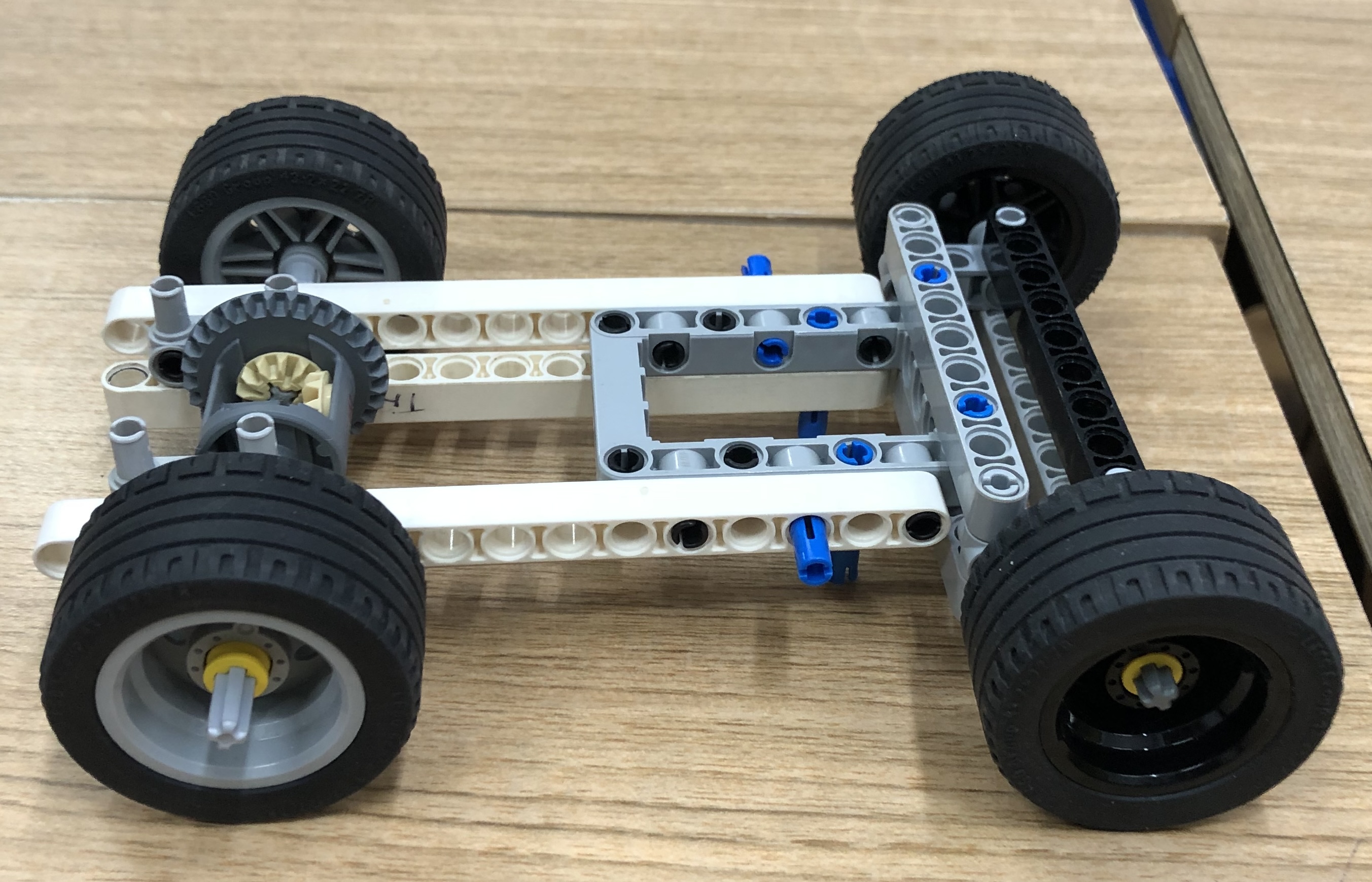
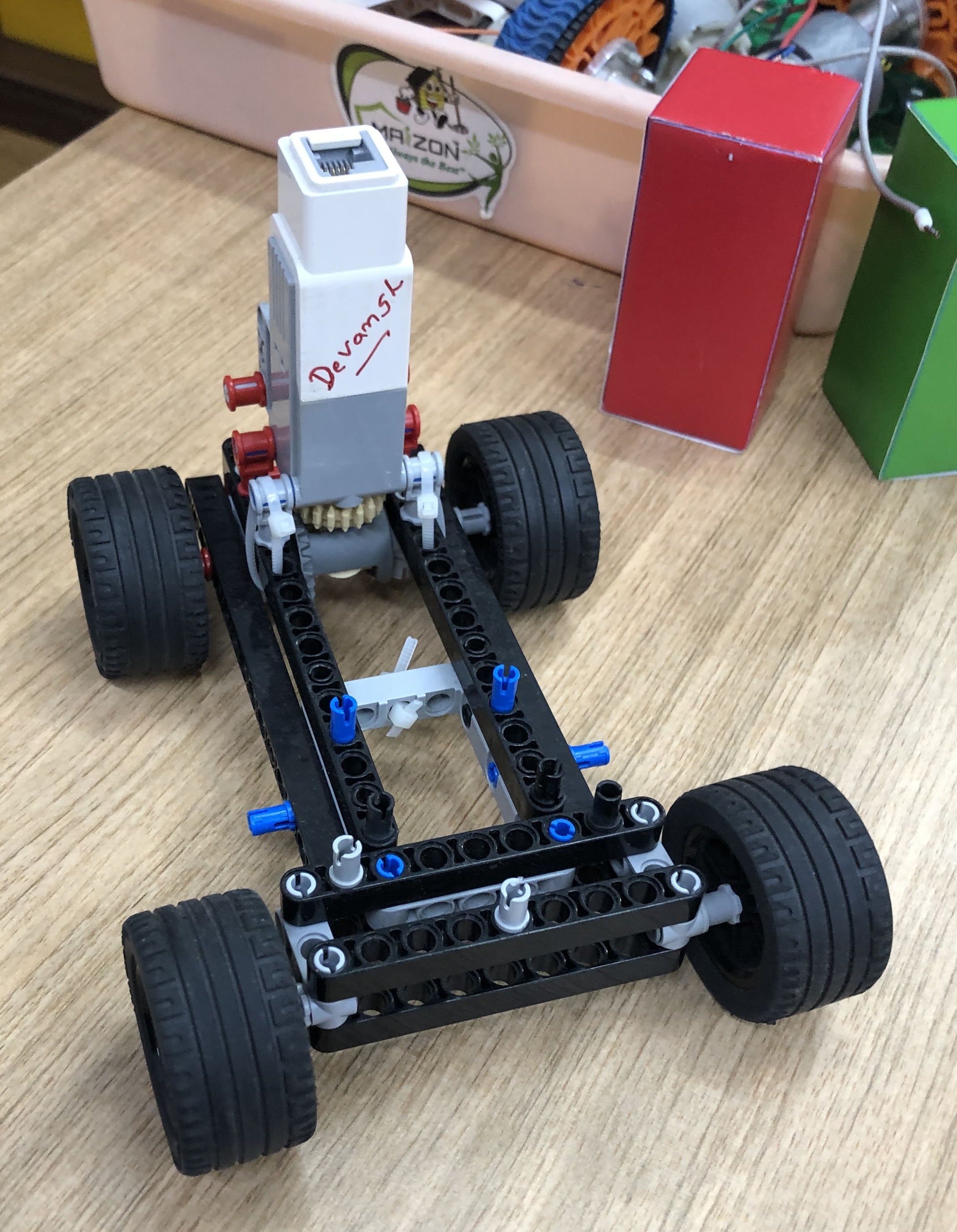
We designed our own robot chassis with differential gear axle and steering
 |  |
|---|
First prototype of motor attachment with vertical orientation secured by zip ties
 |
|---|
3D printed assembly to attach servo motor to steering
 |
|---|
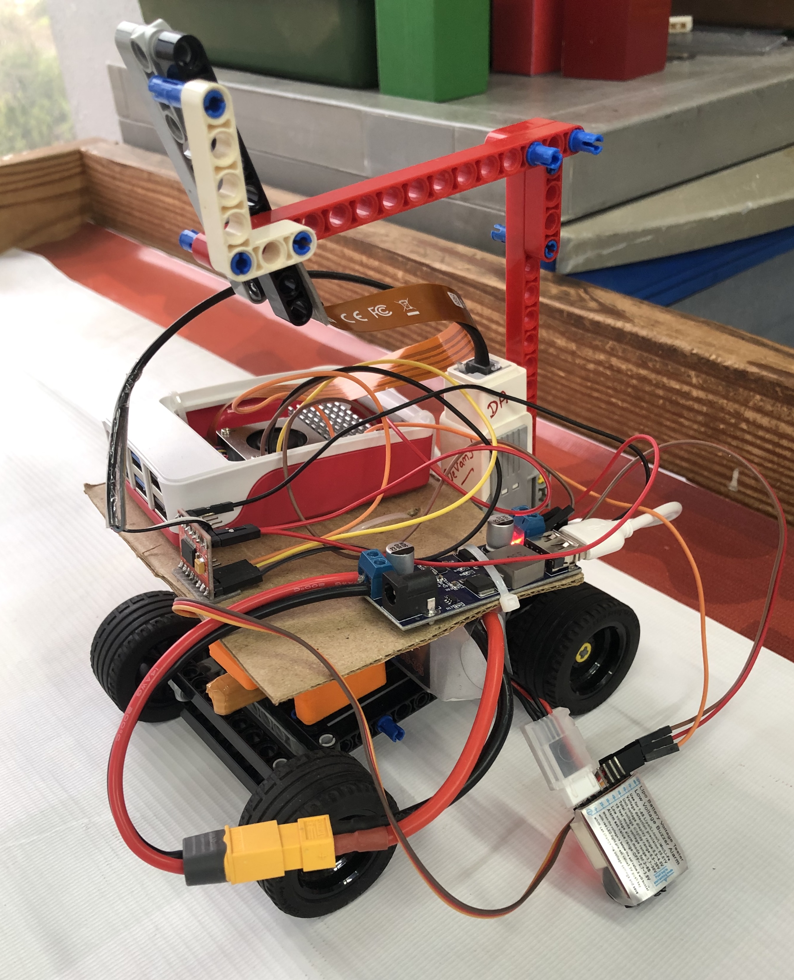
Mounted Raspberry Pi5 on a cardboad sheet, battery, power converter, axle motor, motor driver and servo motor for steering
 |
|---|
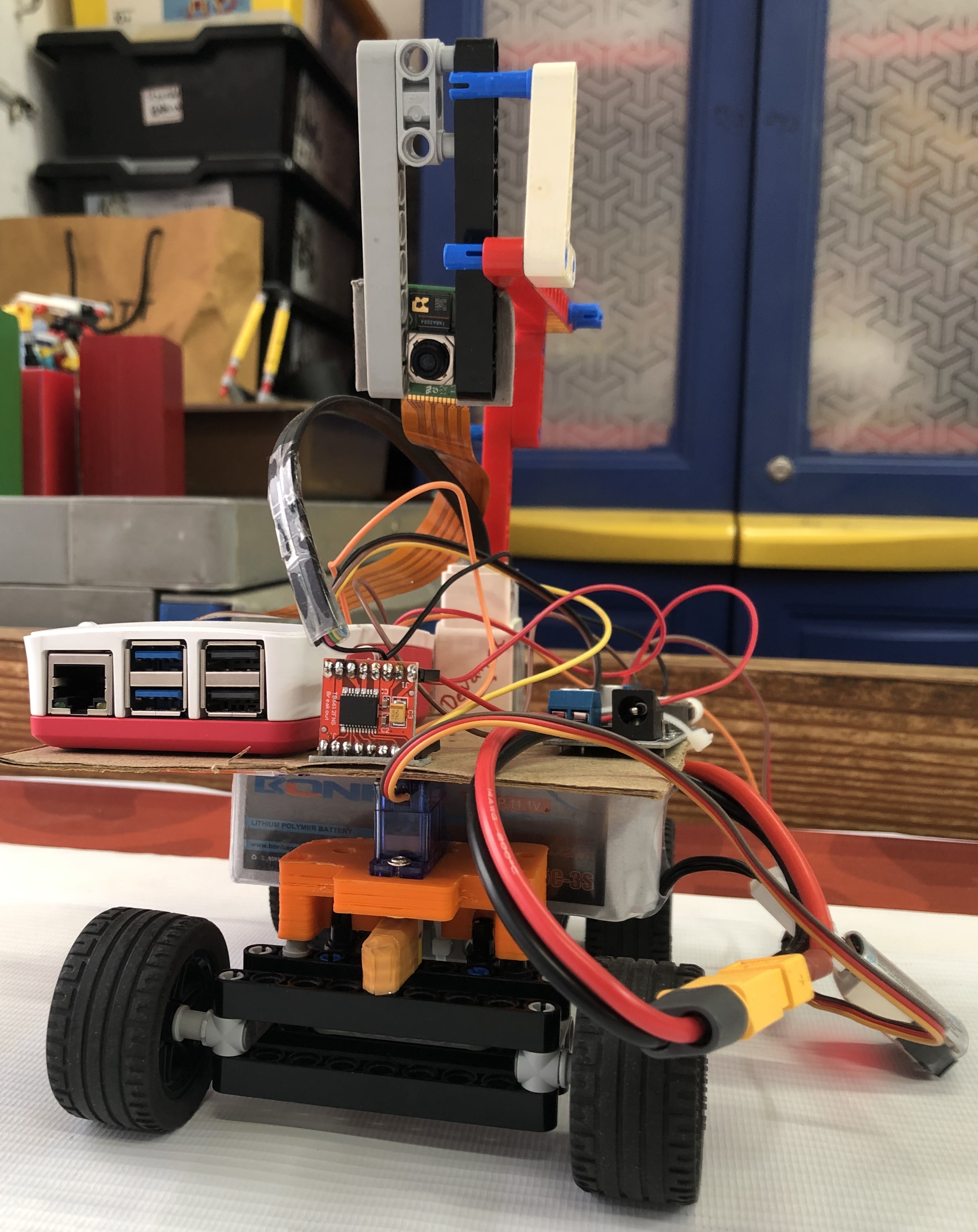
Adding a camera so that our robot can see!
 |
|---|
Moving the components to a lego base plate to make it more stable
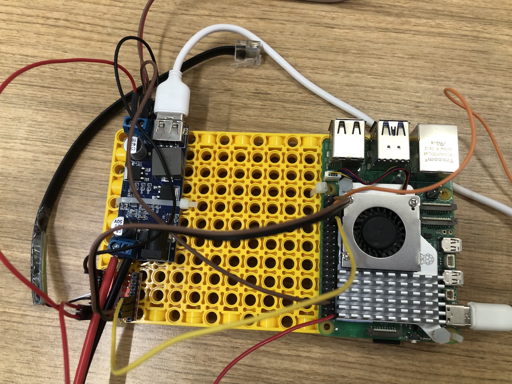 |
|---|
Attaching the lego base plate to the robot chassis along with distance sensors
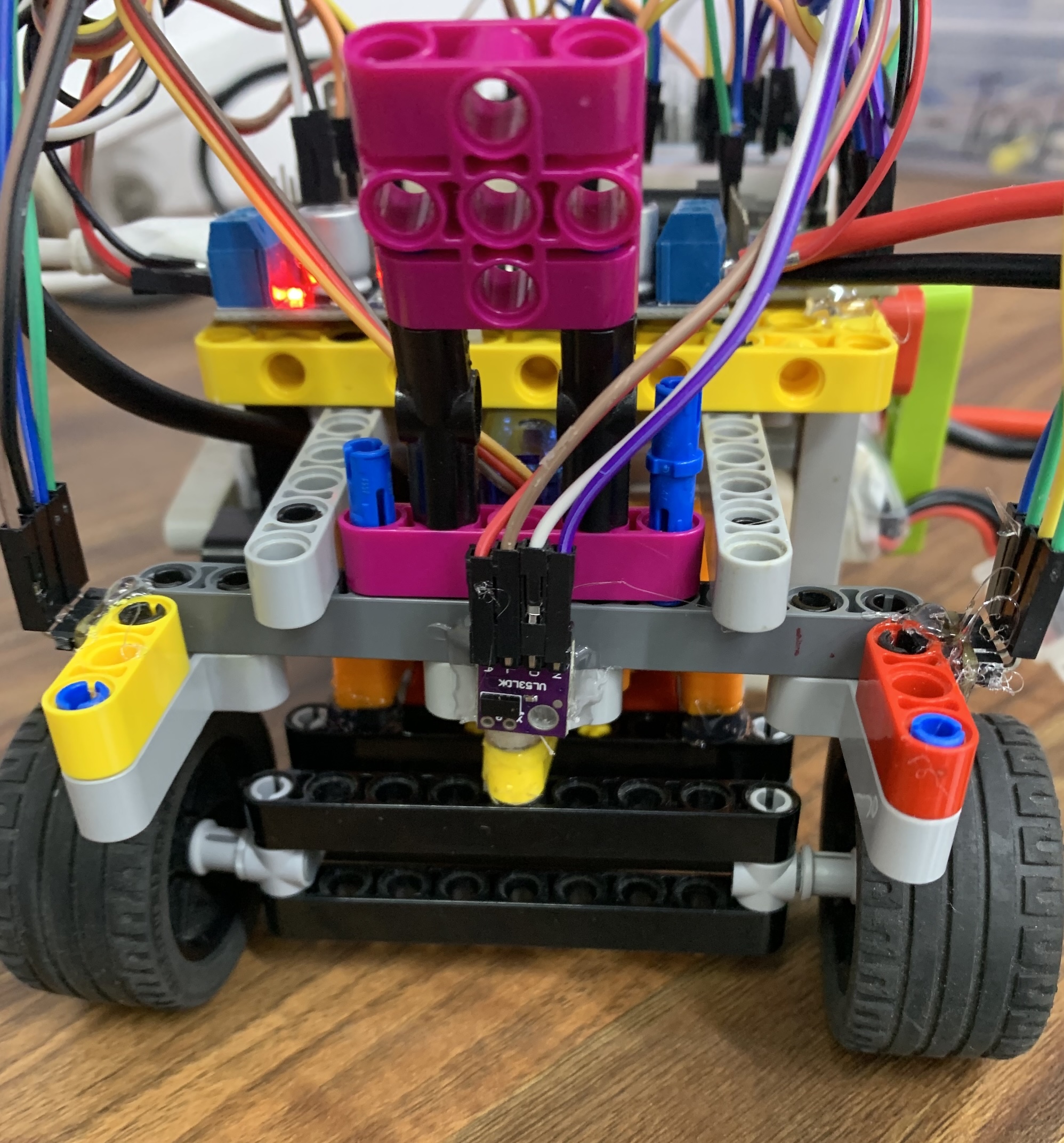 |
|---|
All components connected with wires and bread board power rail for electrical prototyping
 |
|---|
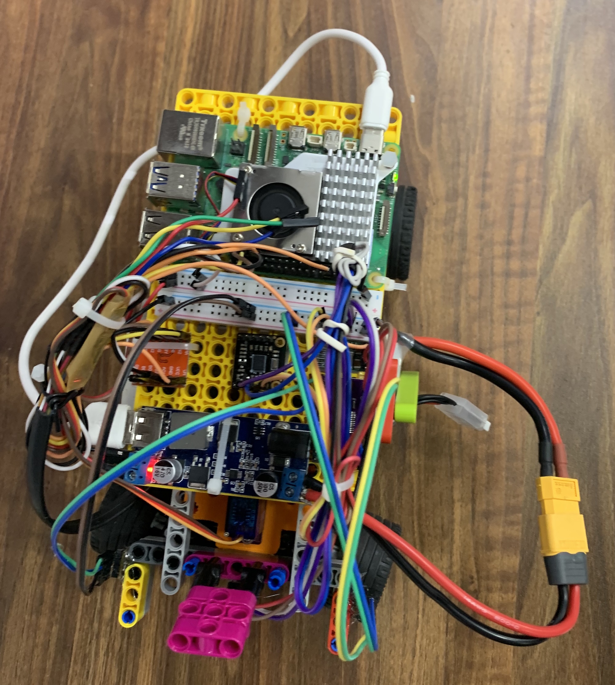
A jungle of wires!
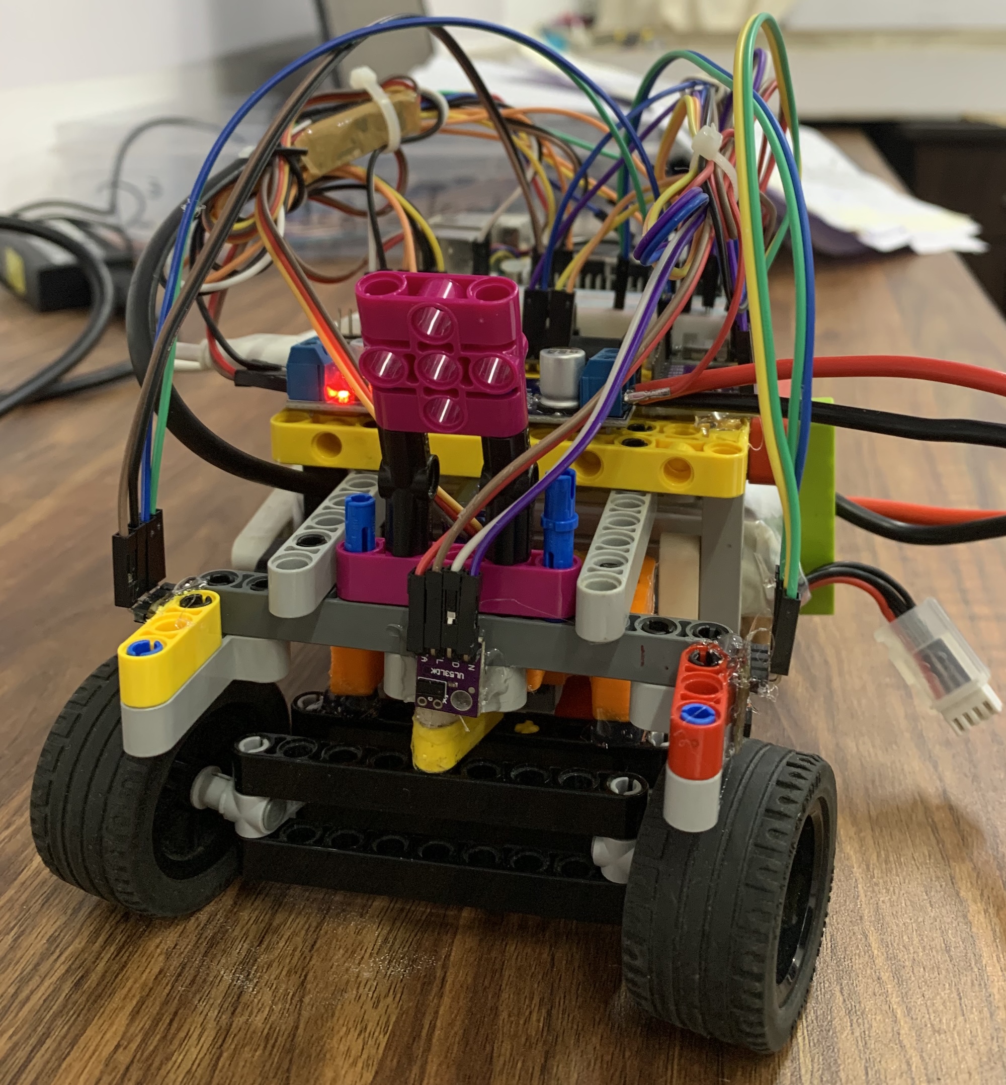 | 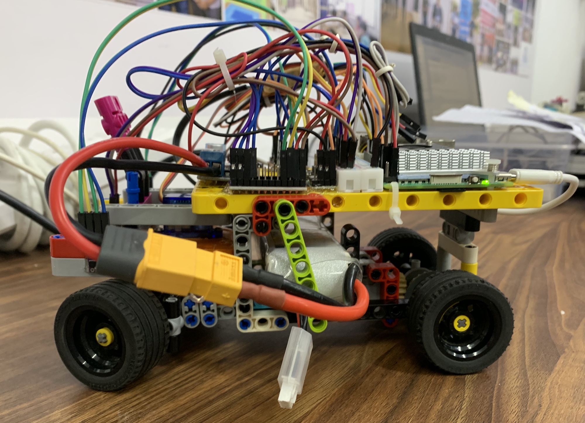 |
|---|
Tied the wires neatly and upgraded the sensors
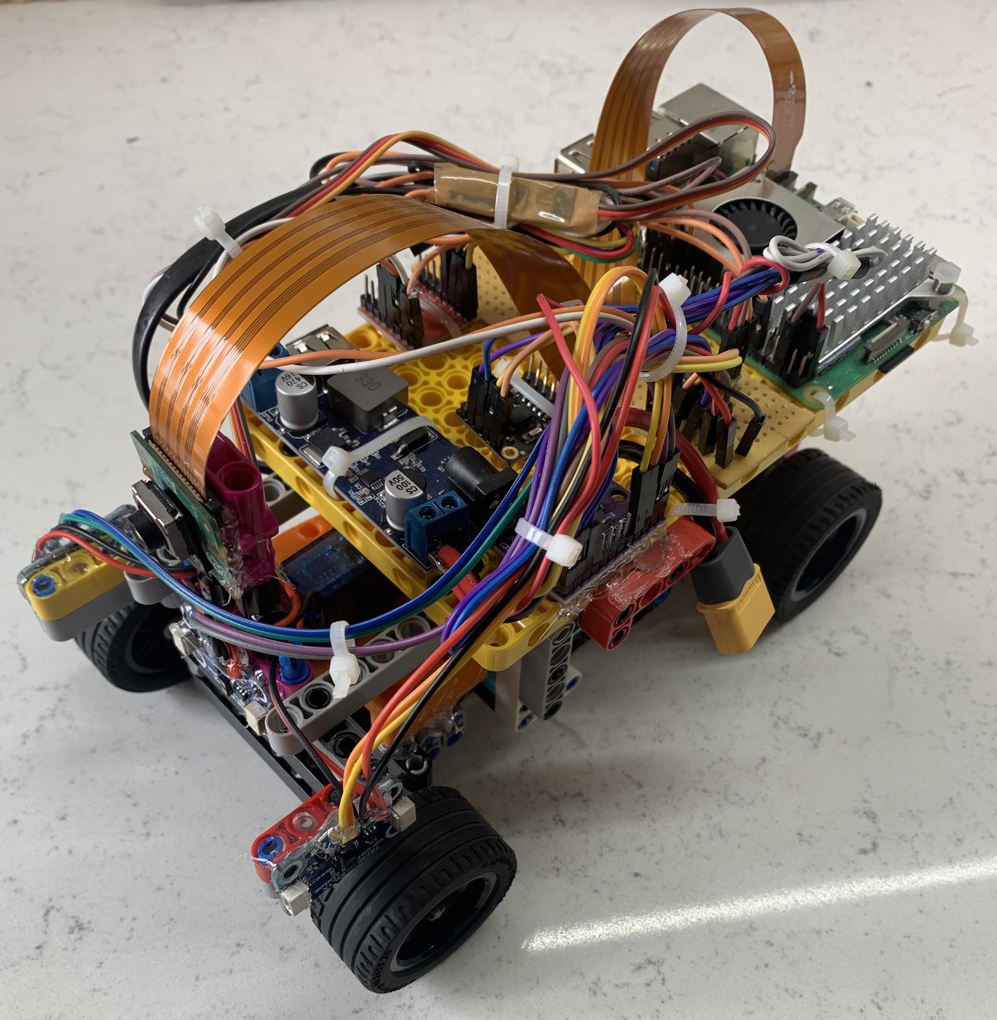 |
|---|
Created a custom PCB to solve the wire mess and to make the connections reliable
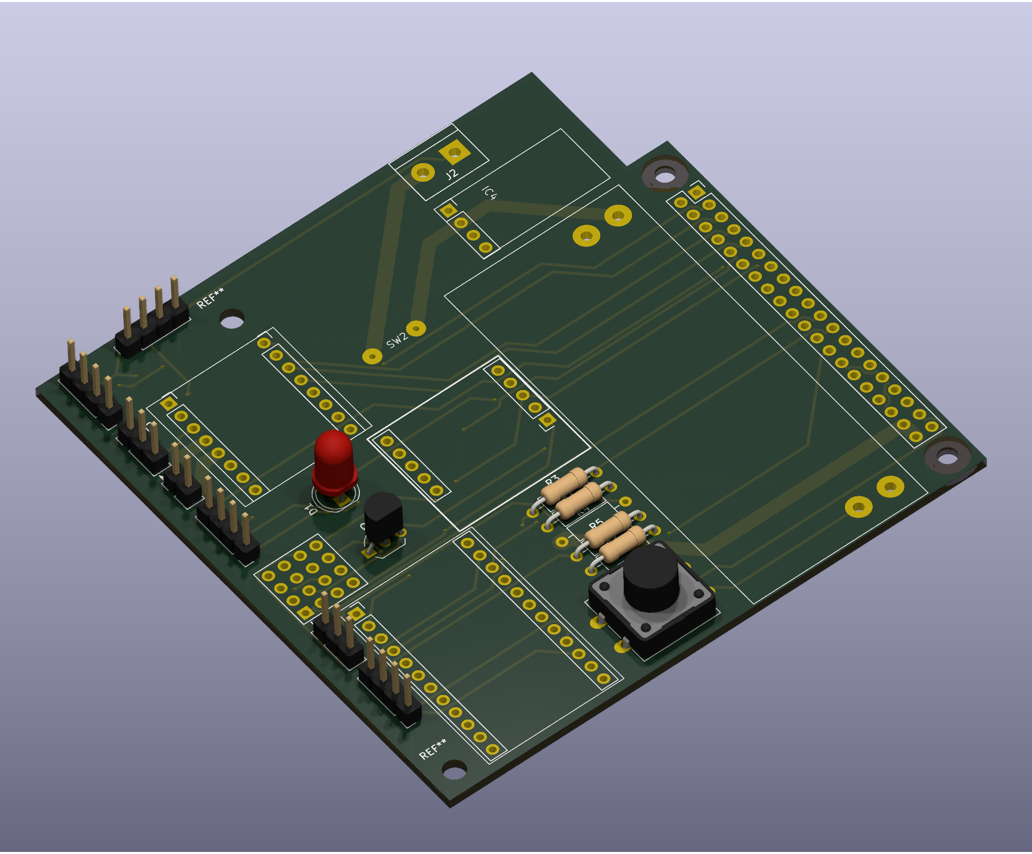 | 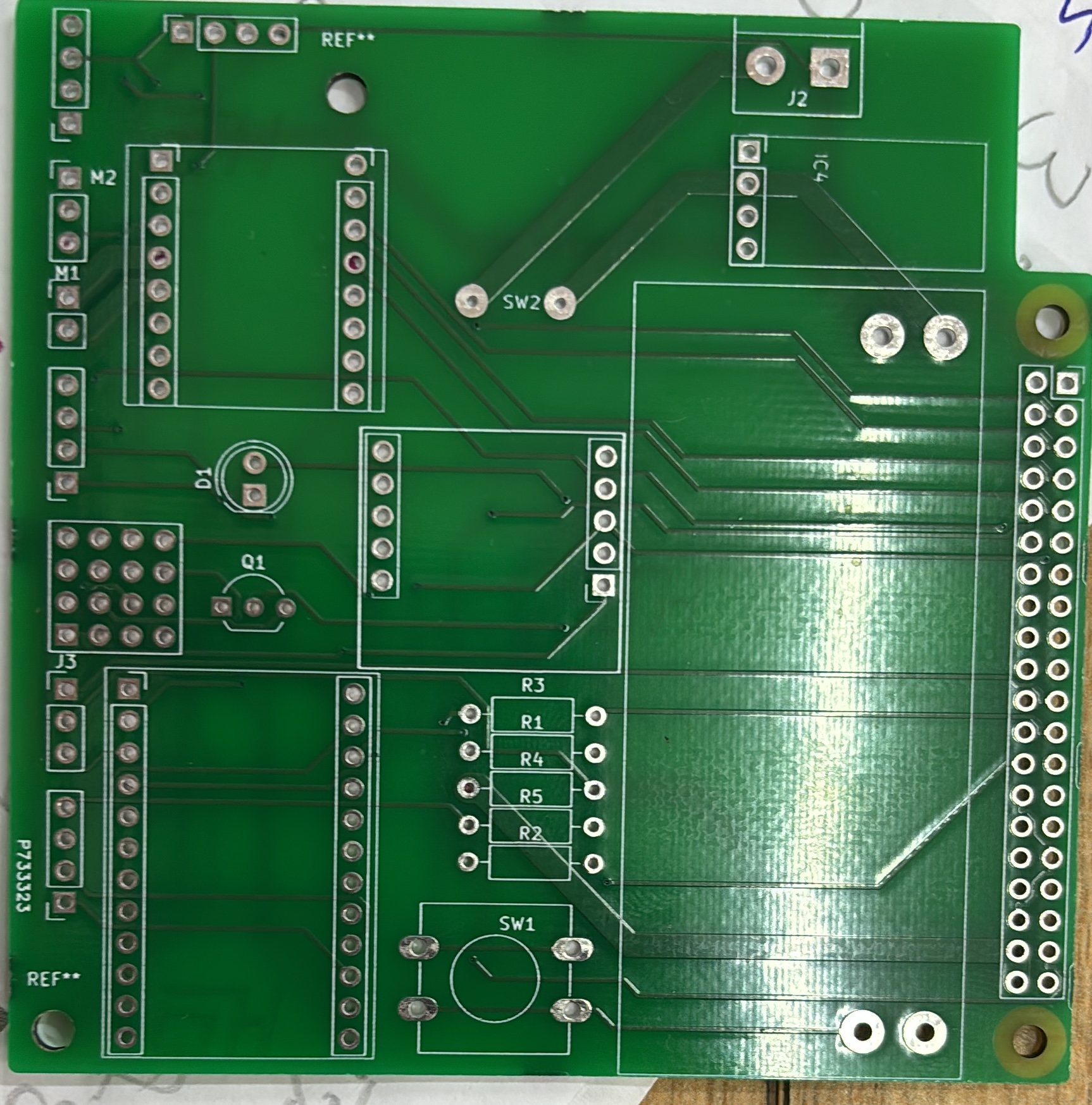 |
|---|---|
 | 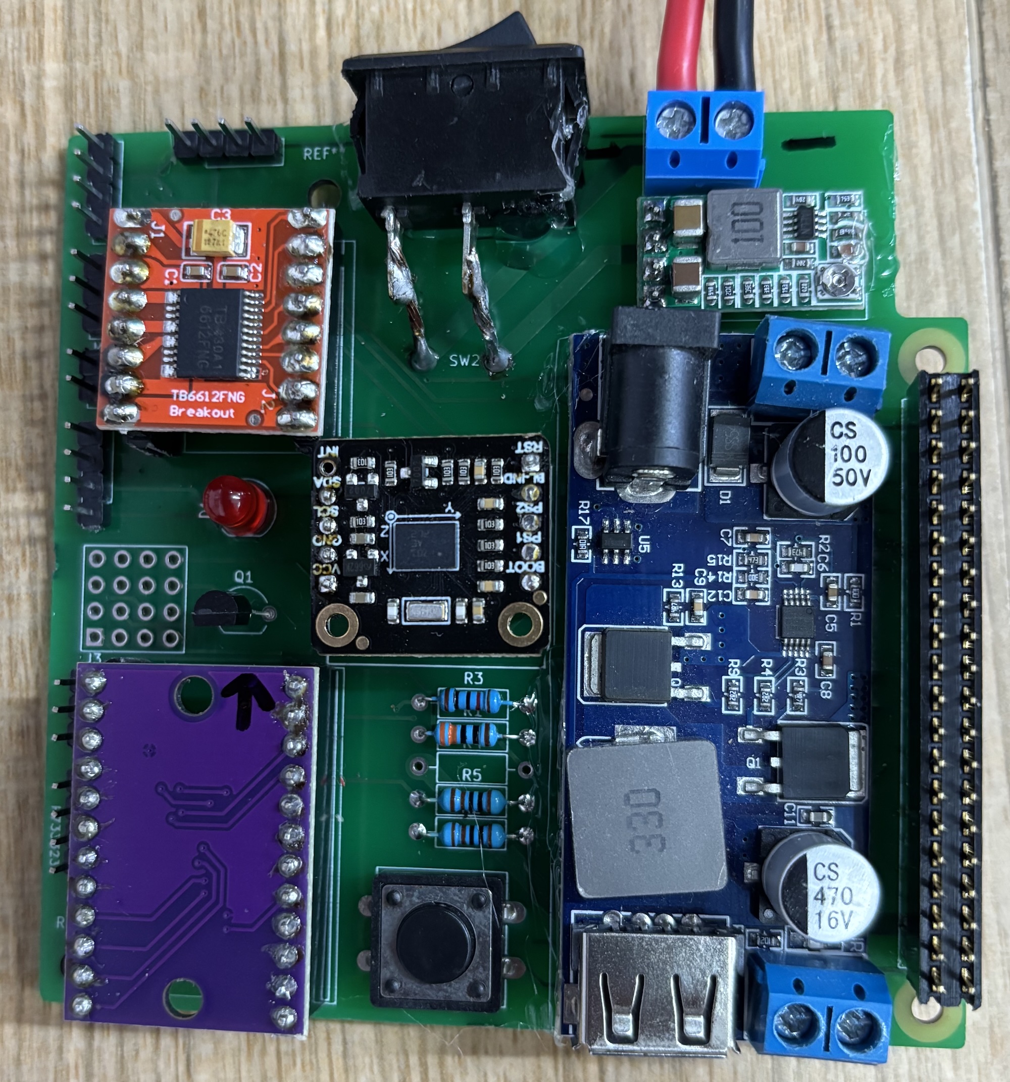 |
Moved to a custom PCB
 |  |
|---|
Aligned the battery so that it doesn't protrude outside the robot
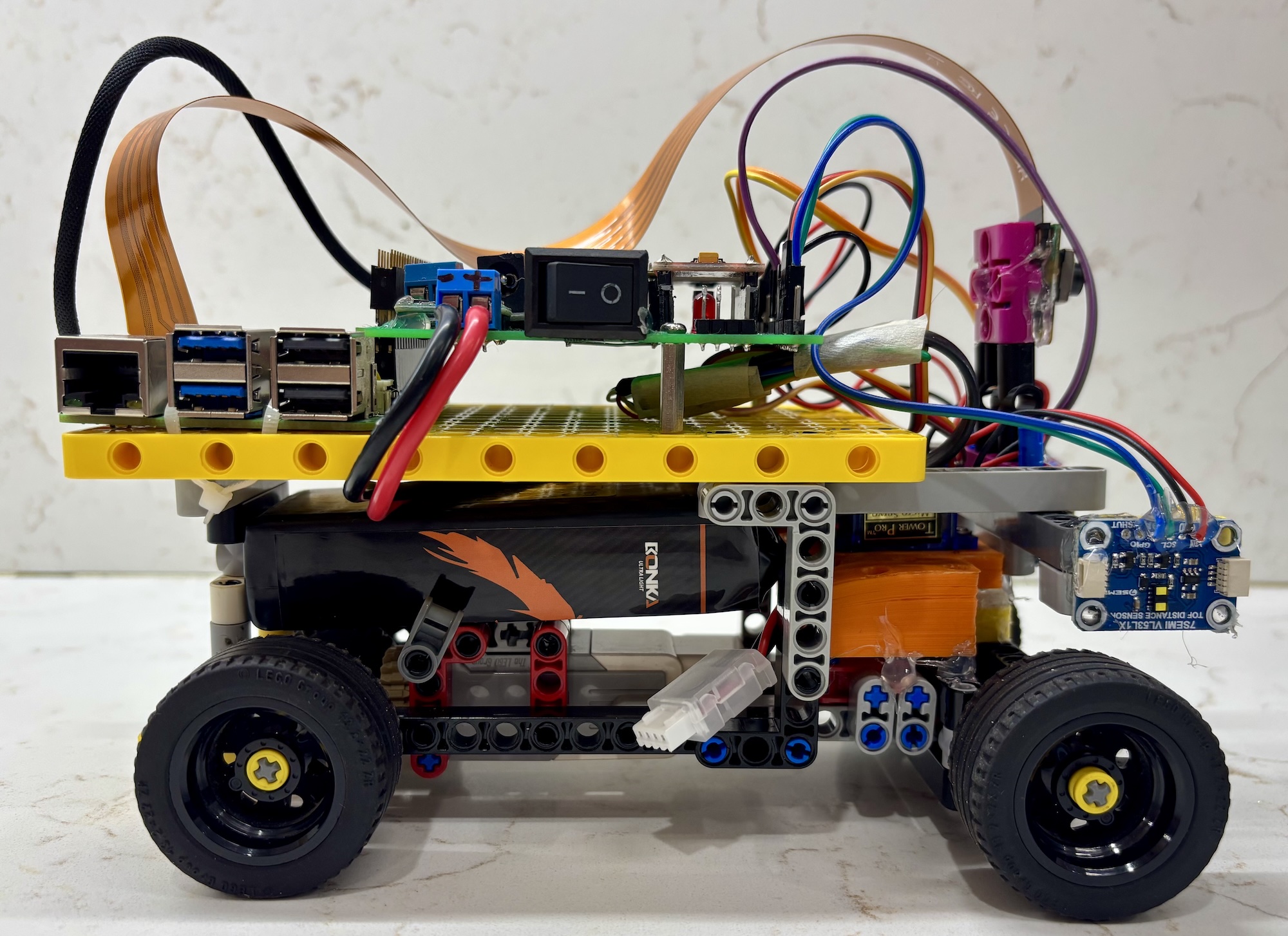 |
|---|
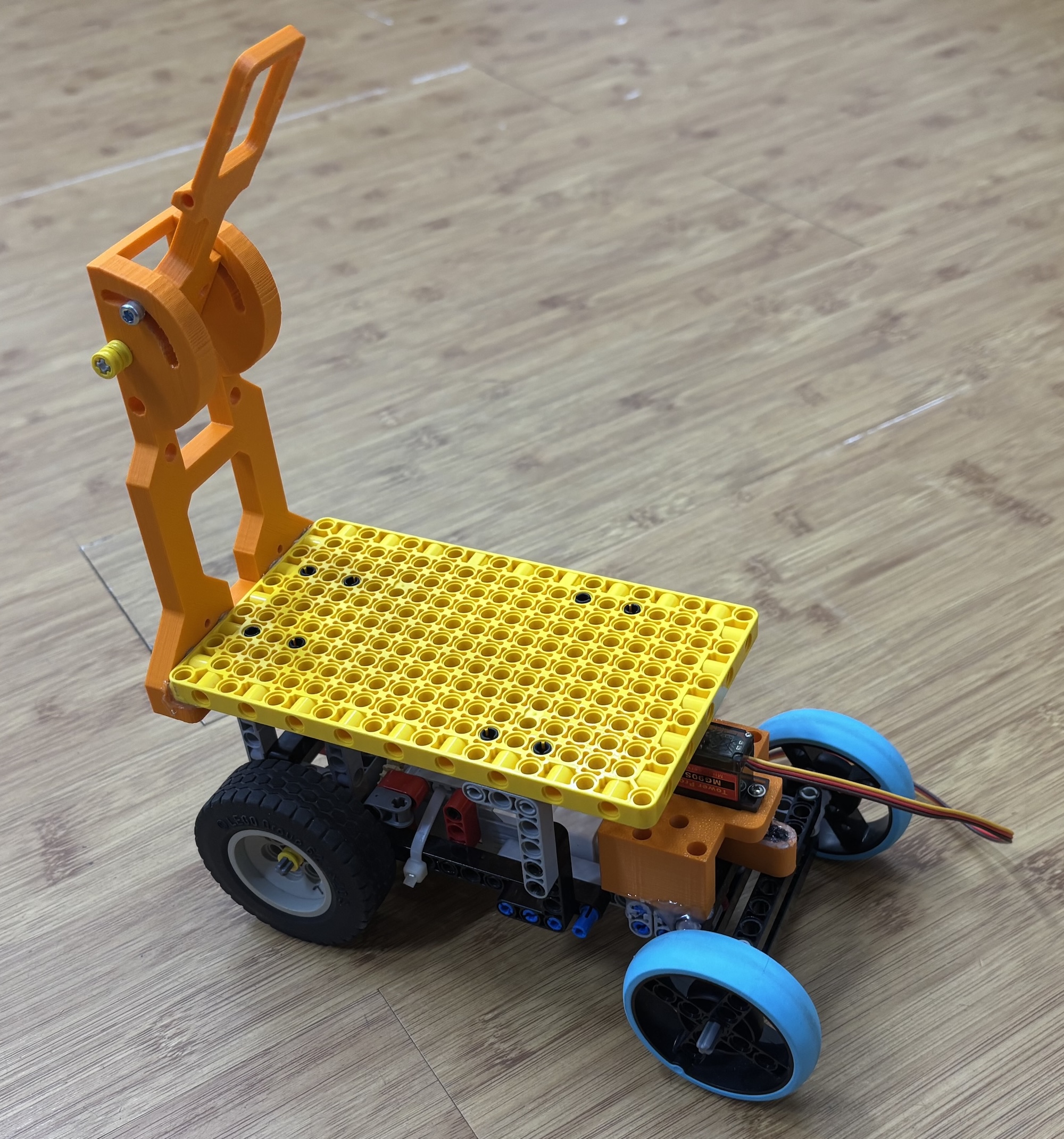 | 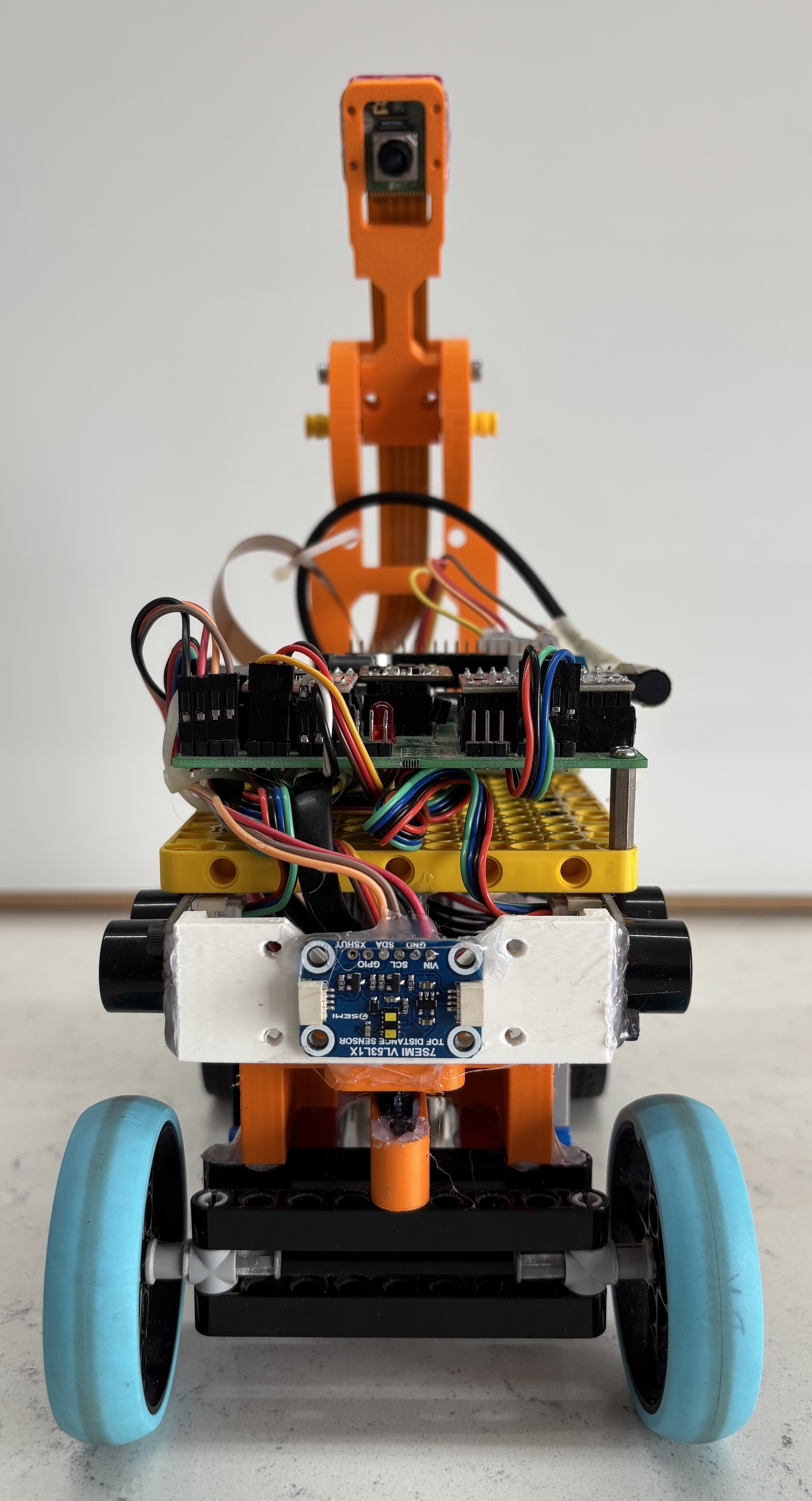 |
|---|---|
| Changed the wheels and designed a custom 3D printed camera mount. Moved the camera to vehicle rear to improve FOV. | Designed a custom 3D printed sensor mount for stable mounting of distance sensors. Designed a 3D printed horn coupling for servo motor. |
models/chassis folder. Recommended settings
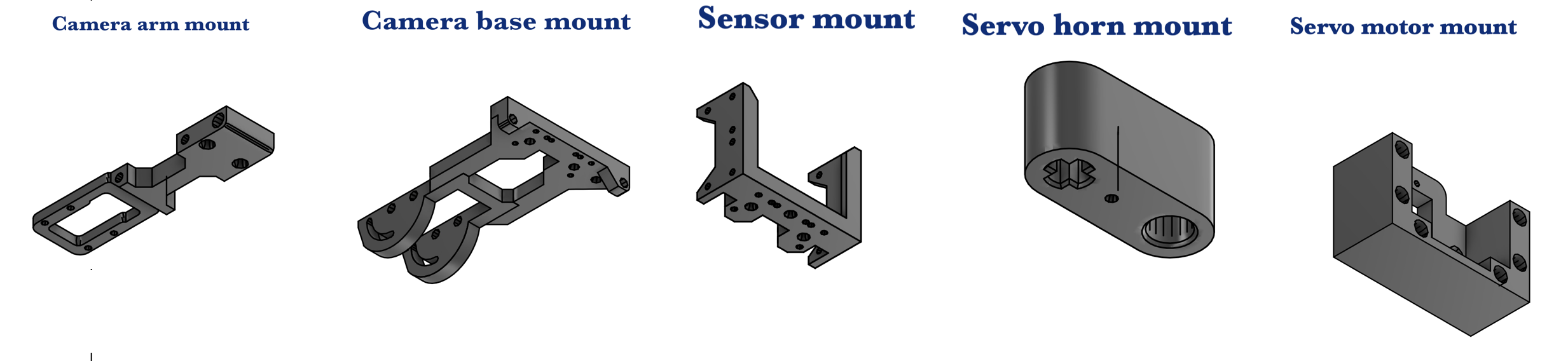
 |  | 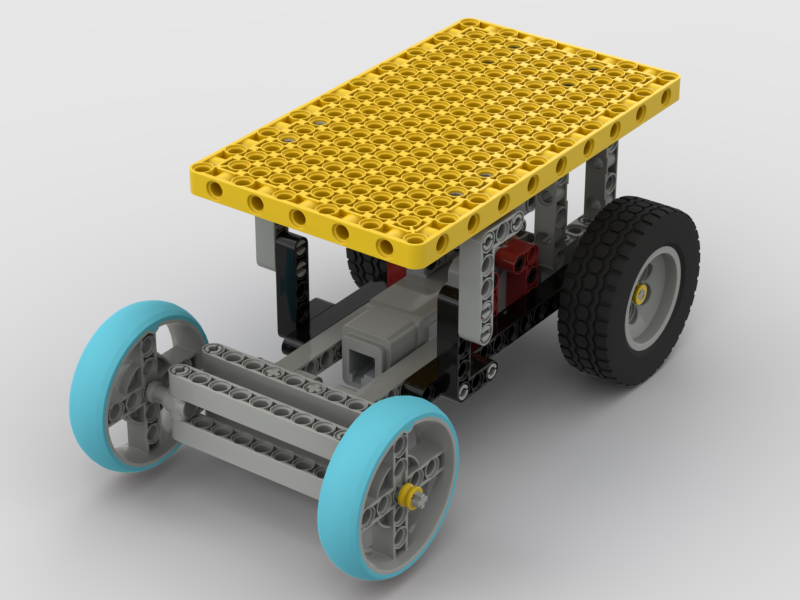 |
|---|
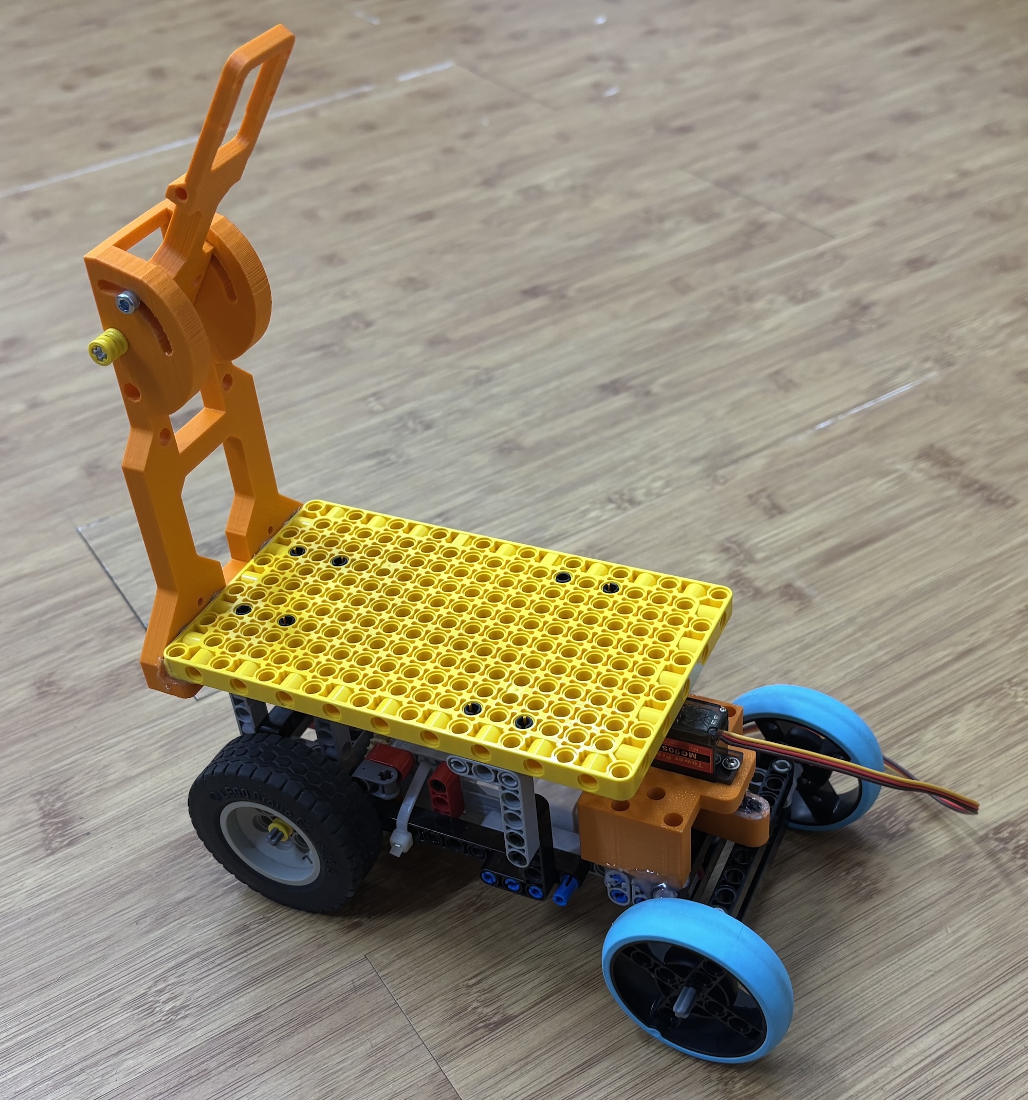
models/PCB folder using KiCAD (https://www.kicad.org/)
pip3 install adafruit-circuitpython-bno055pip3 install adafruit-circuitpython-tca9548apip3 install adafruit-circuitpython-vl53l1xsrc folder to the Raspberry Pi5/src/open_challenge/main.py for Open challenge/src/obstacle_challenge/main_v3.py for Obstacle challengeOne major challenge we faced was in working with the VL53L8CX ToF sensor. We have placed it on the back of our robot to aid in parking, but it was extremely unreliable and onerous to work with during testing. The sensor lacked a dedicated Python library (only providing a C-based library), and refused to communicate through our I²C multiplexer. These limitations made integration unexpectedly difficult for us.
To connect this sensor, we first created our own Python version of the C library. Then, we moved the sensor to a secondary I²C bus to bypass the multiplexer and eliminate communication conflicts.
The sensor failed roughly once in every twenty readings. We wanted to make the sensor more reliable. To solve, this, we went deep into the technical documentation of the sensor and realised that the Raspberry Pi ports were configured as pull down instead of pull ups. Since this fix the sensor has never failed.
Another major challenge arose when we tried to use a fish-eye lens in place of our camera for image detection. We wanted to use a fish-eye lens, as it had a wider Field Of View (195 degrees) than our Raspberry Pi Camera Module 3 (120 degrees)
Unfortunately, this didn’t work out. The fish-eye camera has a circular lens, which means all images we received were distorted and circular. This made it difficult to calculate their area, which hindered accuracy. Oftentimes, blocks would be detected either too early or too late. While we could have attempted to add circular ROIs, this would have added significant complexity to the bot and would have required extensive tuning.
Our team used Github to store all of our code such that it is accessible to all team members and to those who wish to use this repository in the future. We have made frequent commits to this repository, and this repository stands as testament to our efforts, and the process of design as a whole
t-photos contains 2 photos of the team (an official one and one funny photo with all team members)v-photos contains 6 photos of the vehicle (from every side, from top and bottom)video contains the video.md file with the link to a video where driving demonstration existsschemes contains several schematic diagrams of the electronic components, chassis, circuit diagram and 3D part imagessrc contains code of control software for all components which were programmed to participate in the competitionmodels is for the design files for models used for 3D printing and PCB manufacturingother is for other files which can be used to understand how to prepare the vehicle for the competition.src/
├── motors/
│ ├── motor.py # DC motor control
│ ├── servo.py # Servo steering control
│ └── test_pwm.py # PWM testing
├── sensors/
│ ├── camera.py # Camera module interface
│ ├── distance.py # Distance sensor reading
│ ├── bno055.py # IMU/Gyro sensor
│ ├── color_tuning.py # Color detection tuning
│ └── vl53l1x.py # ToF sensor driver
├── open_challenge/
│ ├── main.py # Open challenge algorithm
│ └── config.py # Configuration parameters
└── obstacle_challenge/
├── main_v3.py # Obstacle challenge algorithm
├── config.py # Configuration parameters
└── nationals/ # National competition version| Qty | Value | Footprint | References |
|---|---|---|---|
| 4 | VL53l1x | Connector_PinSocket_2.54mm:PinSocket_1x04_P2.54mm_Vertical | U1, U2, U3, U4 |
| 3 | 1K | Resistor_THT:R_Axial_DIN0207_L6.3mm_D2.5mm_P10.16mm_Horizontal | R2, R4, R5 |
| 2 | 330 | Resistor_THT:R_Axial_DIN0207_L6.3mm_D2.5mm_P10.16mm_Horizontal | R1, R3 |
| 1 | BC547 | Package_TO_SOT_THT:TO-92_Inline_Wide | Q1 |
| 1 | Conn_01x03_Pin | Connector_PinHeader_2.54mm:PinHeader_1x03_P2.54mm_Vertical | J3 |
| 1 | LED | LED_THT:LED_D5.0mm | D1 |
| 1 | Motor_DC | Connector_PinHeader_2.54mm:PinHeader_1x02_P2.54mm_Vertical | M1 |
| 1 | Motor_Servo | Connector_PinHeader_2.54mm:PinHeader_1x03_P2.54mm_Vertical | M2 |
| 1 | SW_Push | Button_Switch_THT:SW_PUSH-12mm | SW1 |
| 1 | SW_SPST | Resistor_THT:Untitled | SW2 |
| 1 | Screw_Terminal_01x02 | TerminalBlock:TerminalBlock_bornier-2_P5.08mm | J2 |
| 1 | ~ | Converter_DCDC:Untitled_1 | IC5 |
| 1 | ~ | Module:Untitled | IC6 |
| 1 | ~ | Connector_PinSocket_2.54mm:Untitled | J1 |
| 1 | ~ | Motor driver:Untitled | IC2 |
| 1 | ~ | I2C expansion boards:Untitled | IC3 |
| 1 | ~ | Sensor_Motion:DFRobot bno005 breakout board | IC1 |
| 1 | ~ | Converter_DCDC:12v to 9v buck converter | IC4 |
The 24 most common of 26 parts.
It measures 86 × 85 mm and has 2 copper layers, 1.6 mm thick.
26 parts, built around the VL53L1X and BC547. The full list of its parts is on this page, with links to each part's symbol and footprint where PCBKit's library has them.
From the Devansh-awat/greenbotics repository on GitHub, at the commit this page was made from: the board is models/PCB/Untitled.kicad_pcb and its schematic models/PCB/Untitled.kicad_sch. PCBKit opens the board in the browser, with nothing to install.
Its repository states no licence, so its author keeps all rights: ask Devansh-awat before reusing the design.

valerionew/53xLIDAR
53xLIDAR is a solid state, 16 points lidar, based on ST's VL53L1x sensors

CloudyPadmal/CrazyFlieToFDeck
This repository contains KiCAD source files and generated gerber files for CrazyFlie Obstacle Avoidance Sensor Deck.

equationstratos/STRATOSDRONES
A 4-layer, 36×70 mm Tello-style portrait controller board for the STRATOSDRONE: chip-down ESP32-P4 (flight + camera + hardware H.264) with an ESP32-C6-MINI-1 Wi-Fi co-processor, IMU / barometer / ToF / optical-flow…

Honzaaa45/cube-hologram-pcb
Carte electronique d'un afficheur holographique Pepper's Ghost : CAO KiCad 4 couches entierement generee par du code et verifiee automatiquement

MaxJ02/Death_By_Table
Code for the autonomous RC-car "Death_By_Table", which competed in the YRGO Grand Prix 2023. The code is written for the Arduino Nano which uses the Atmega328p microcontroller.

