


2 layers78 × 58 mm

 denis-gz/pw-meter
EMB_1 graduation project
Pw meter is an open-source printed circuit board by denis-gz, from the denis-gz/pw-meter repository on GitHub. It is a 4-layer board of 100 × 50 mm with 71 parts on 69 nets, routed with 349 tracks and 69 vias.
It is built around the ESP32-S3-WROOM-1-N8, AP63205WU and AMS1117-3.3, with the USBLC6-2SC6, PEC11R-4215F-S0024 and KT-0603R among its other parts. Its parts include 23 resistors, 19 capacitors, 6 ICs, 4 connectors and 3 diodes. It belongs with the ESP32 boards of this library.



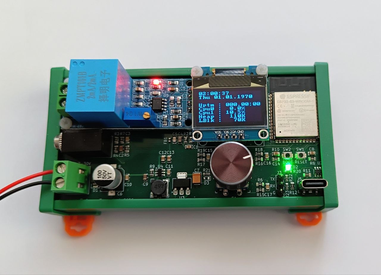
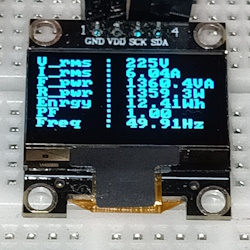
The Power Meter can be attached to the AC mains load to measure the following parameters:
In case you have assembled the board using the schematic and components specified in the KiCad project, follow these steps to bring it to life:
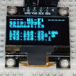
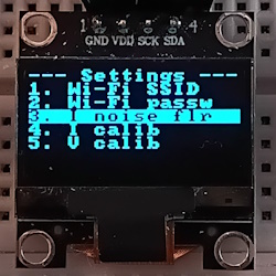
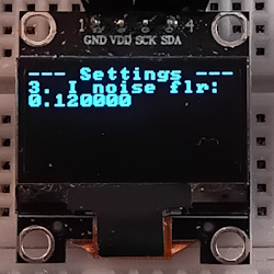
sdkconfig to match actual hardware. Use usual idf.py menuconfig command to re-generate the sdkconfig. See also sdkconfig.defaults file for the minimal set of parameters that differ from ESP-IDF defaults (regenerate it with idf.py save-defconfig after changing the configuration).I noise floor parameter high enough to prevent bogus readings.0–F): the first four characters of the firmware's ELF SHA256. It is printed at every boot in the console line I (...) app_init: ELF file SHA256: 53ba1e2f1... (PIN 53BA in this example), or can be computed from the build output with sha256sum build/pw-meter.elf (certutil -hashfile build\pw-meter.elf SHA256 on Windows). The PIN changes with every build. Rotate the encoder to choose each digit and press to confirm it. Once unlocked, the settings stay accessible until the display goes to sleep (60 seconds without interaction). The menu covers Wi-Fi credentials, MQTT broker URI, credentials, topic and reporting period, noise floors, calibration coefficients and the energy counter. Text and numeric values are entered in the serial console (UART0 on J3, 921600 baud) when prompted. Settings are stored in NVS and survive reboots.The project consists of a main board and two sub-boards:
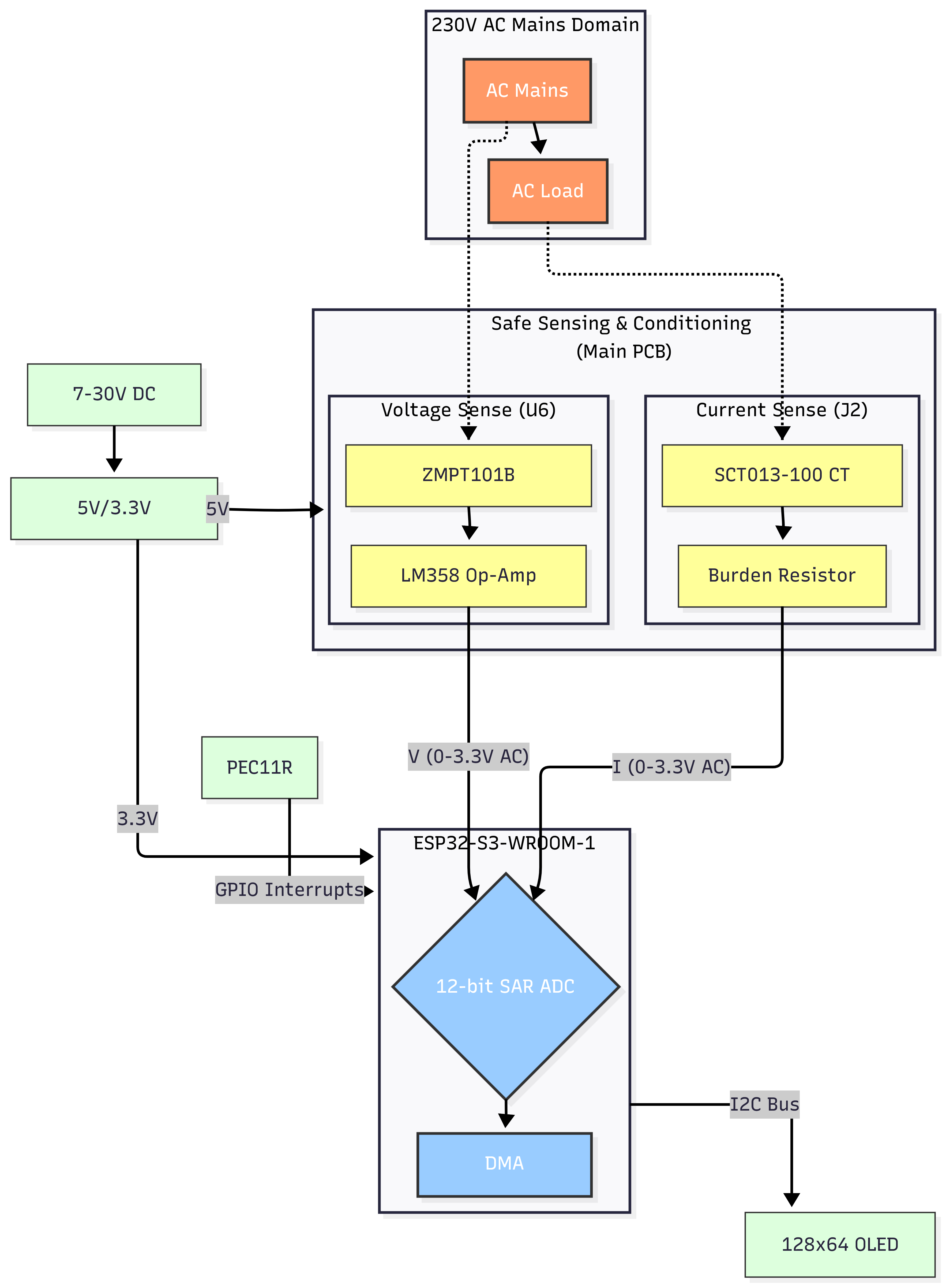
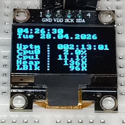
idf.py menuconfig).Sampling of AC voltage and current channels occur in DMA continuous mode, the rate is 4 kHz per channel, with 12 bit resolution and 12 dB attenuation. The samples are then adjusted for non-linearity using pre-calibrated curves, centered at 0 level, and processed using DSP capabilities of ESP32-S3 chip. Employing hardware acceleration helps keep CPU usage reasonably low (~10% on Core 1, or only 5% without display output).
Please find further details on project's Schematic, and PCB board views (Top Layer, Inner 1, Inner 2, Bottom Layer and 3D View).
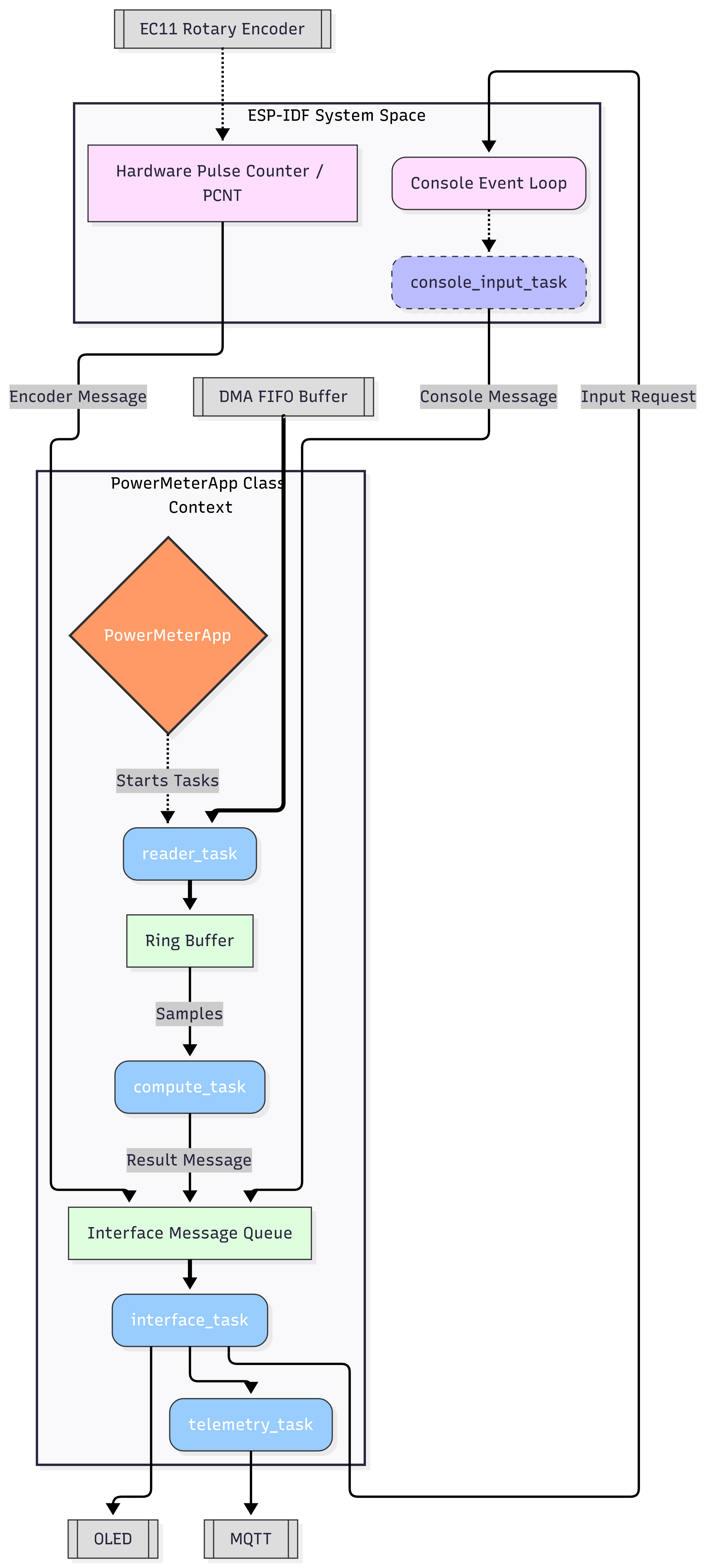
The software consists of 6 tasks:
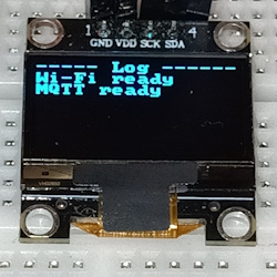
reader_task: ADC sampling task. Performs reading, parsing and adjustment of analog data. Outputs raw values in mV to a ring buffer for the Compute Task.compute_task: Processes data in 10-cycle chunks. Performs all mathematical calculations and outputs results to the queue for the Interface Task.interface_task: Applies filtering, updates the OLED display, handles user input from the rotary encoder and console. Sends a copy of the UI data to the Telemetry Task.telemetry_task: Maintains Wi-Fi and MQTT connections and publishes data to the MQTT broker as JSON, to the <topic>/metrics/power and <topic>/metrics/device sub-topics.indicator_task: Drives the status LED (Wi-Fi searching, connected, MQTT transmit and error blinks).console_input_task: A service task created by the console event loop that handles prompts and waits for user input from the UART console.The PowerMeterApp class represents the main class which initializes all tasks and waits for a stop event. It handles task shutdown, and the app_main() function recreates the instance if needed.
nopnop2002/ssd1306: OLED display support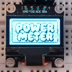
Copyright © Denys Zavorotnyi, 2026
| Qty | Value | Footprint | References |
|---|---|---|---|
| 12 | 10k | Resistor_SMD:R_0805_2012Metric | R1, R2, R4, R5, R6, R8, R10, R15, R16, R17, R18, R19 |
| 7 | 100 nF | Capacitor_SMD:C_0805_2012Metric | C3, C5, C11, C15, C16, C17, C18 |
| 4 | 1k | Resistor_SMD:R_0603_1608Metric | R20, R21, R22, R23 |
| 3 | 10 uF | Capacitor_SMD:C_0805_2012Metric | C2, C4, C19 |
| 2 | 1 uF | Capacitor_SMD:C_0805_2012Metric | C8, C14 |
| 2 | 22 uF | Capacitor_SMD:C_0805_2012Metric | C12, C13 |
| 2 | 4.7k | Resistor_SMD:R_0805_2012Metric | R13, R14 |
| 2 | 5.1k | Resistor_SMD:R_0805_2012Metric | R11, R12 |
| 1 | 100k | Resistor_SMD:R_0805_2012Metric | R9 |
| 1 | 100nF 50V | Capacitor_SMD:C_0805_2012Metric | C10 |
| 1 | 100uF 50V | Capacitor_SMD:CP_Elec_8x10.5 | C6 |
| 1 | 10uF 50V | Capacitor_SMD:C_0805_2012Metric | C9 |
| 1 | 15 | Resistor_SMD:R_0805_2012Metric | R3 |
| 1 | 1k | Resistor_SMD:R_0805_2012Metric | R7 |
| 1 | 22 nF | Capacitor_SMD:C_0805_2012Metric | C1 |
| 1 | 22 uF | Capacitor_Tantalum_SMD:CP_EIA-3528-21_Kemet-B | C7 |
| 1 | 4.7uH | footprints:L_SXN-SDRH5D28 | L1 |
| 1 | AC current input | PJ-325C5-G:XKB_PJ-325C5-G | J2 |
| 1 | AMS1117-3.3 | Package_TO_SOT_SMD:SOT-223-3_TabPin2 | U3 |
| 1 | AP63205WU | Package_TO_SOT_SMD:TSOT-23-6 | U4 |
| 1 | BLM18PG121SH1D | digikey-footprints:0603 | FB1 |
| 1 | BOOT | Button_Switch_SMD:SW_SPST_B3U-1000P | SW2 |
| 1 | DC 7-30V | TerminalBlock_Phoenix:TerminalBlock_Phoenix_MKDS-1,5-2-5.08_1x02_P5.08mm_Horizontal | J1 |
| 1 | ESP32-S3-WROOM-1 | RF_Module:ESP32-S3-WROOM-1 | U1 |
| 1 | GM009605v4.3 | footprints:MODULE_GM009605v4.3 | U5 |
| 1 | Green | LED_SMD:LED_0603_1608Metric | D2 |
| 1 | LC_Tech_HW697_Module | footprints:LC_Tech_HW697_Module | U6 |
| 1 | PEC11R | digikey-footprints:Rotary_Encoder_Switched_PEC11R | S1 |
| 1 | RESET | Button_Switch_SMD:SW_SPST_B3U-1000P | SW1 |
| 1 | Red | LED_SMD:LED_0603_1608Metric | D3 |
| 1 | SS34 | Diode_SMD:D_SMA | D1 |
| 1 | UART | Connector_PinHeader_2.54mm:PinHeader_1x03_P2.54mm_Vertical | J3 |
| 1 | USB JTAG/Serial | Connector_USB:USB_C_Receptacle_G-Switch_GT-USB-7051x | J5 |
| 1 | USBLC6-2SC6 | Package_TO_SOT_SMD:SOT-23-6 | U2 |
The 60 most common of 71 parts.

laminarforge/laminarforge-cad
Parametric CAD models (Rust + vcad) for LaminarForge open-source LAMP diagnostics device

Kilan777/HomeDeck
Jarvis HomeDeck: a Raspberry Pi CM4 carrier board and voice-assistant software for a 7-inch smart display (KiCad hardware, generated from Python, plus the Python/JS assistant)

wvianna/mcp-kicad-vscode
Workspace que combina um servidor MCP para automação de design de PCB com KiCad e o projeto de hardware (placa de circuito impresso) desenvolvido com ele.

jmcpheron/pico-quorum
Several people, several keys, one Safe. Hardware approvals for Safe multisig wallets.


FujiNetWIFI/fujinet-hardware
Schematics and design files for FujiNet hardware

Matyas604/Security-Alarm-Panel
Home Assistant Smart Home Alarm Control Panel with fingerprint reader, NFC/RFID card reader, motion radar, and touchscreen TFT display. It can control your smart home, not just your home security system.
It measures 100 × 50 mm and has 4 copper layers, 1.6 mm thick.
71 parts, built around the ESP32-S3-WROOM-1-N8, AP63205WU, AMS1117-3.3 and USBLC6-2SC6. The full list of its parts is on this page, with links to each part's symbol and footprint where PCBKit's library has them.
From the denis-gz/pw-meter repository on GitHub, at the commit this page was made from: the board is pcb/pcb.kicad_pcb and its schematic pcb/pcb.kicad_sch. PCBKit opens the board in the browser, with nothing to install.
Its repository states no licence, so its author keeps all rights: ask denis-gz before reusing the design.