2 layers65 × 56.5 mm
PiSupply
enwi/PiSupply
Uninterruptable power supply for Raspberry Pi's, which can also power external HDDs
80 parts4LGPL-3.0

 Matyas604/Security-Alarm-Panel1
Home Assistant Smart Home Alarm Control Panel with fingerprint reader, NFC/RFID card reader, motion radar, and touchscreen TFT display. It can control your smart home, not just your home security system. Backlit with LED strip and automatic brightness control. And more
Security Alarm Panel is an open-source printed circuit board by Matyas604, from the Matyas604/Security-Alarm-Panel repository on GitHub, published under the GPL-3.0 licence. It is a 2-layer board of 100 × 73.9 mm with 132 parts on 116 nets, routed with 989 tracks and 201 vias.
It is built around the 74AHCT125D, CC1101RGP and ESP32-S3-WROOM-1-N8, with the AP63205WU, MT3608 and AP2114H-3.3TRG1 among its other parts. Its parts include 33 capacitors, 25 resistors, 14 connectors, 11 ICs and 10 inductors. It belongs with the home automation and IoT and radio and wireless boards and the ESP32 boards of this library.


Once at school, we went to the storage room for waste and discarded items, since I’m studying at a technical school, there was mostly electronics there. Basically, an entire security system had been discarded there—it was still functional, but had already been taken out of service. I really liked the security keypad, and since I’d seen a few videos showing that I could build an entire security system using Home Assistant—and since I have Home Assistant—I took the keypad with me to try connecting it to an ESP and integrating it into Home Assistant. In the end, I found out it wouldn’t work because the communication is encrypted and runs on 12V. So it actually came to me—why not create my own security keypad? And not just a keypad, but an entire control panel that would control not only the security system but also other things in smart home.
I really enjoyed this project, it was probably my biggest and longest project yet. Mainly because of the PCB-it’s probably the most complex one I’ve ever designed. And I actually learned a few new things along the way.
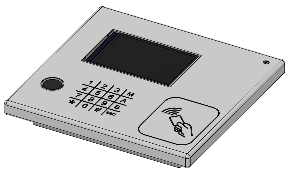
Made in Fusion360
Everything is housed in a nice panel consisting of two parts: the bottom part, witch is screwed to the wall, and the top cover, witch snaps onto it. The modules and PCB are secured inside with M3 screws and heat inserts. The entire panle is set back 15 mm from the wall to allow for smooth backlighting. The dimensions are: height 173 mm, width 179 mm, and depth 28 mm.
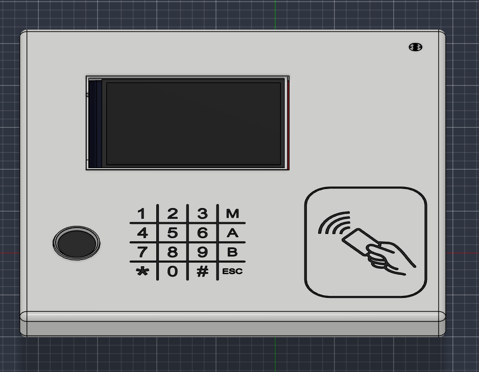
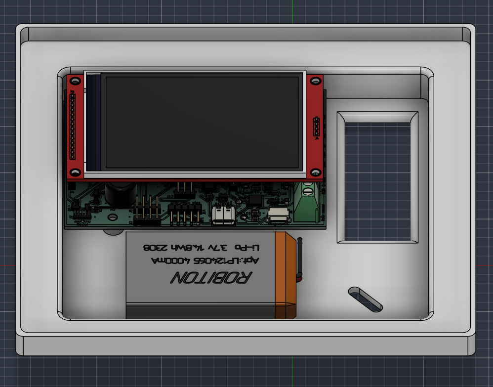
Made in Fusion360
Schematic
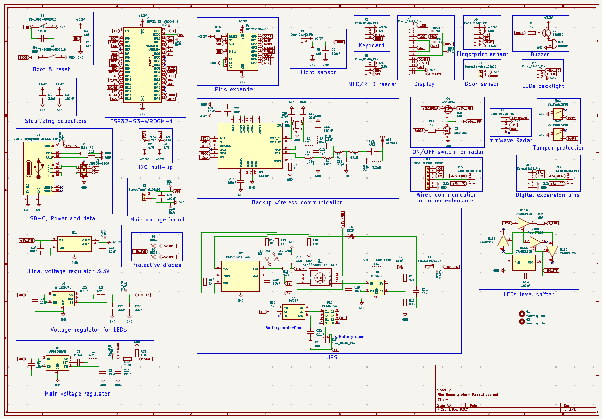
PCB
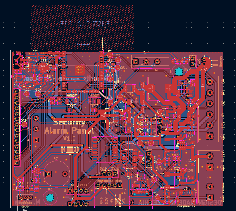
Made in KiCad
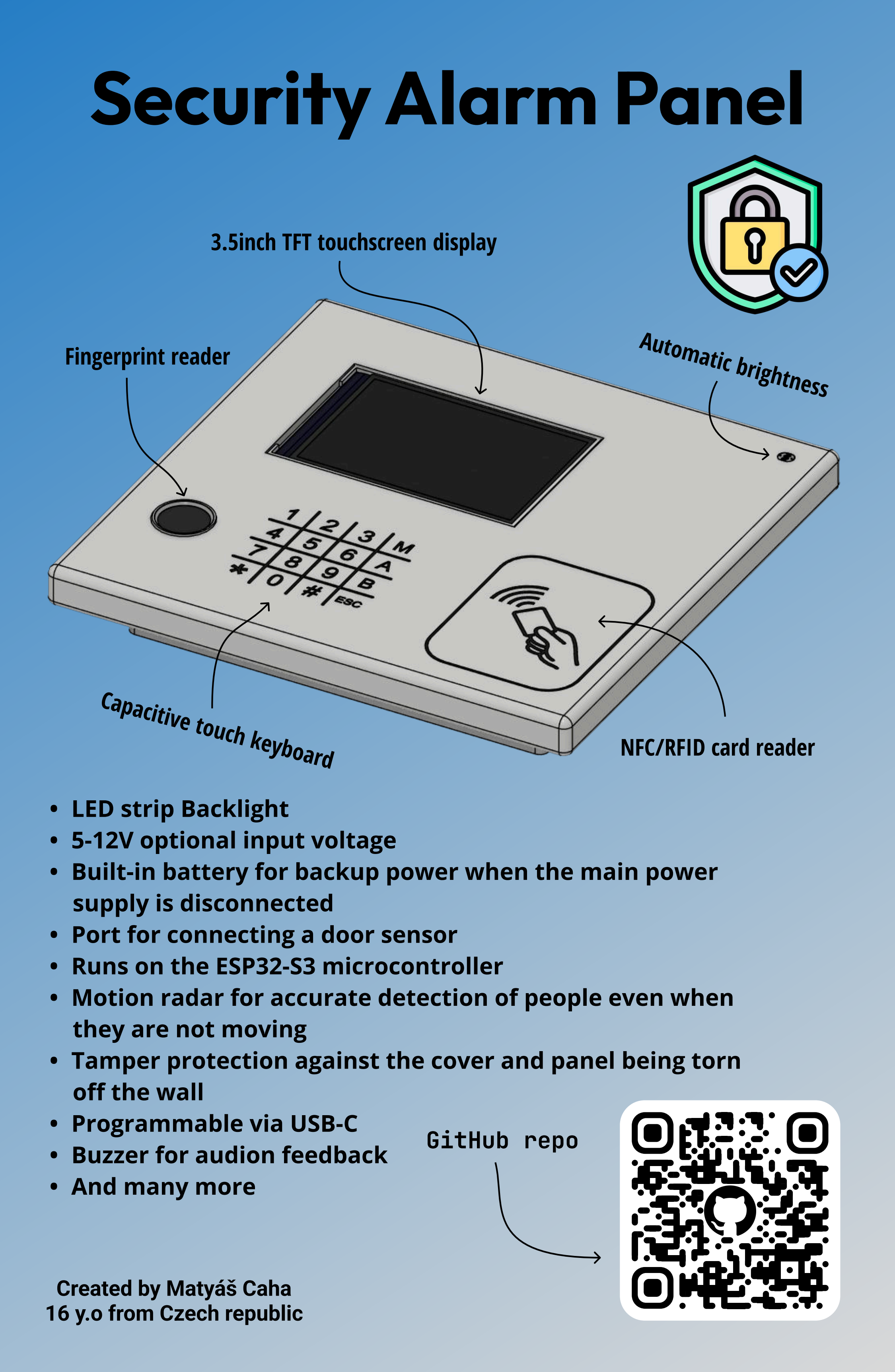
Made in Figma
This alarm panel uses ESPHome firmware. It is programmed via the USB-C port. A lot of things can be configured directly in Home Assistant. Once the project will be finished, I’ll publish a detailed description of the features, functions and instructions on how to set it up. You can view the entire code here. The code is quite long—it has 848 lines. Here is an example from the code that automatically adjusts the brightness of the panel backlight and display based on the room lighting:
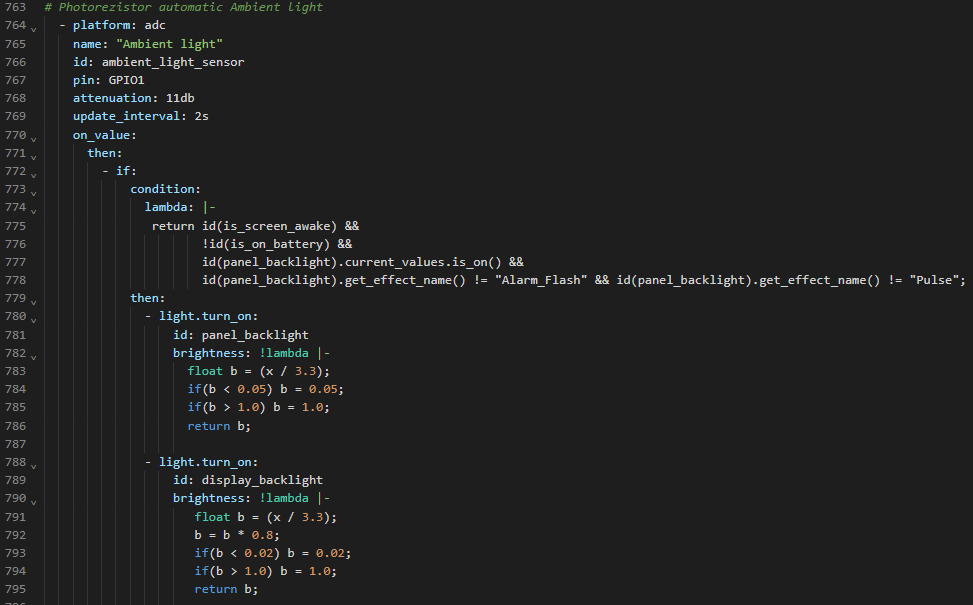
Made in ESPHome Device Builder
You can find it in .csv format here.
This project is licensed under the GNU GPL v3.
Matyas604/Security-Alarm-Panel - Smart Security Panel for Home Assistant
Copyright (C) 2026 Matyáš Caha

This program is free software: you can redistribute it and/or modify
it under the terms of the GNU General Public License as published by
the Free Software Foundation, either version 3 of the License, or
(at your option) any later version.

This program is distributed in the hope that it will be useful,
but WITHOUT ANY WARRANTY; without even the implied warranty of
MERCHANTABILITY or FITNESS FOR A PARTICULAR PURPOSE. See the
GNU General Public License for more details.

You should have received a copy of the GNU General Public License
along with this program. If not, see <https://www.gnu.org/licenses/>.
Made with ❤️ by @Matyas604
| Qty | Value | Footprint | References |
|---|---|---|---|
| 7 | 10uF | Capacitor_SMD:C_0805_2012Metric | C6, C7, C23, C24, C29, C30, C31 |
| 5 | 10k | Resistor_SMD:R_0805_2012Metric | R3, R9, R10, R15, R25 |
| 5 | 1k | Resistor_SMD:R_0805_2012Metric | R8, R12, R13, R20, R24 |
| 5 | 22uF | Capacitor_SMD:C_0805_2012Metric | C2, C9, C10, C26, C27 |
| 4 | 100nF | Capacitor_SMD:C_0805_2012Metric | C3, C4, C5, C33 |
| 4 | 12nH | Inductor_SMD:L_0603_1608Metric | L2, L3, L6, L7 |
| 4 | 4.7k | Resistor_SMD:R_0805_2012Metric | R5, R6, R16, R22 |
| 3 | 0.1uF | Capacitor_SMD:C_0805_2012Metric | C8, C25, C32 |
| 3 | Conn_01x03_Pin | Connector_PinHeader_2.54mm:PinHeader_1x03_P2.54mm_Vertical | J11, J13, J15 |
| 3 | LOGO | LOGO | G***, G***, G*** |
| 2 | 1.5pF | Capacitor_SMD:C_0603_1608Metric | C14, C15 |
| 2 | 100nF | Capacitor_SMD:C_0603_1608Metric | C11, C22 |
| 2 | 18nH | Inductor_SMD:L_0603_1608Metric | L4, L5 |
| 2 | 27pF | Capacitor_SMD:C_0603_1608Metric | C19, C20 |
| 2 | 4.7uH | Inductor_SMD:L_6.3x6.3_H3 | L1, L9 |
| 2 | 5.1k | Resistor_SMD:R_0805_2012Metric | R1, R2 |
| 2 | 9.1k | Resistor_SMD:R_0805_2012Metric | R17, R23 |
| 2 | AP63205WU | Package_TO_SOT_SMD:TSOT-23-6 | U4, U6 |
| 2 | Conn_01x04_Pin | Connector_PinHeader_2.54mm:PinHeader_1x04_P2.54mm_Vertical | J2, J5 |
| 2 | MountingHole | MountingHole:MountingHole_3.2mm_M3 | H1, H2 |
| 2 | SS24 | Diode_SMD:D_SMA | D1, D2 |
| 2 | SS34 | Diode_SMD:D_SMA | D5, D6 |
| 2 | SW_Push_SPDT | Button_Switch_THT:SW_XKB_DM1-16UP-1 | SW1, SW2 |
| 2 | Screw_Terminal_01x02 | TerminalBlock_Phoenix:TerminalBlock_Phoenix_MKDS-1,5-2-5.08_1x02_P5.08mm_Horizontal | J3, J8 |
| 2 | TS-1088-AR02016 | footprints:SW_TS-1088-AR02016 | S1, S2 |
| 1 | 100 | Resistor_SMD:R_0805_2012Metric | R21 |
| 1 | 100R | Resistor_SMD:R_0805_2012Metric | R4 |
| 1 | 100pF | Capacitor_SMD:C_0603_1608Metric | C13 |
| 1 | 100uF | Capacitor_SMD:C_0805_2012Metric | C28 |
| 1 | 10uF | Capacitor_SMD:C_0603_1608Metric | C21 |
| 1 | 12pF | Capacitor_SMD:C_0603_1608Metric | C17 |
| 1 | 1812L150/12DR | Fuse:Fuse_1812_4532Metric | F1 |
| 1 | 1pF | Capacitor_SMD:C_0603_1608Metric | C12 |
| 1 | 1uF | Capacitor_SMD:C_0805_2012Metric | C1 |
| 1 | 26.0 MHz | Crystal:Crystal_SMD_3225-4Pin_3.2x2.5mm | Y1 |
| 1 | 2k | Resistor_SMD:R_0805_2012Metric | R14 |
| 1 | 3.3V | TestPoint:TestPoint_Pad_D2.0mm | 3.3 |
| 1 | 3.3nH | Inductor_SMD:L_0603_1608Metric | L8 |
| 1 | 3.3pF | Capacitor_SMD:C_0603_1608Metric | C16 |
| 1 | 4.7uH - CDRH104R | Inductor_SMD:L_10.4x10.4_H4.8 | L10 |
| 1 | 47k | Resistor_SMD:R_0805_2012Metric | R18 |
| 1 | 47pF | Capacitor_SMD:C_0603_1608Metric | C18 |
| 1 | 5V_LED | TestPoint:TestPoint_Pad_D2.0mm | 5V_LED |
| 1 | 5V_MAIN | TestPoint:TestPoint_Pad_D2.0mm | 5V_MAIN |
| 1 | 5V_UPS | TestPoint:TestPoint_Pad_D2.0mm | 5V_UPS |
| 1 | 5V_USB | TestPoint:TestPoint_Pad_D2.0mm | 5V_USB |
| 1 | 6.2k | Resistor_SMD:R_0805_2012Metric | R19 |
| 1 | 68R | Resistor_SMD:R_0805_2012Metric | R26 |
| 1 | 74AHCT125 | Package_SO:SOIC-14_3.9x8.7mm_P1.27mm | U11 |
| 1 | AO3400A | Package_TO_SOT_SMD:SOT-23 | Q3 |
| 1 | AO3401A | Package_TO_SOT_SMD:SOT-23 | Q4 |
| 1 | AP2114H-3.3TRG1 | footprints:SOT230P700X180-4N | IC1 |
| 1 | Antenna | Connector_Wire:SolderWirePad_1x01_SMD_1x2mm | AE1 |
| 1 | Buzzer | Buzzer_Beeper:Buzzer_12x9.5RM7.6 | BZ1 |
| 1 | CC1101 | footprints:QLP20 | U5 |
| 1 | CEG8205A | Package_SO:TSSOP-8_4.4x3mm_P0.65mm | U10 |
| 1 | Conn_01x02_Pin | Connector_JST:JST_PH_S2B-PH-K_1x02_P2.00mm_Horizontal | J10 |
| 1 | Conn_01x02_Pin | Connector_PinHeader_2.54mm:PinHeader_1x02_P2.54mm_Vertical | J9 |
| 1 | Conn_01x05_Pin | Connector_PinHeader_2.54mm:PinHeader_1x05_P2.54mm_Horizontal | J14 |
| 1 | Conn_01x05_Pin | Connector_PinHeader_1.27mm:PinHeader_1x05_P1.27mm_Vertical | J7 |
| 1 | Conn_01x06_Pin | Connector_JST:JST_SH_SM06B-SRSS-TB_1x06-1MP_P1.00mm_Horizontal | J6 |
| 1 | Conn_01x14_Pin | Connector_PinSocket_2.54mm:PinSocket_1x14_P2.54mm_Vertical | J4 |
| 1 | DW01P | footprints:SOT23-6 | U9 |
| 1 | ESP32-S3-WROOM-1 | RF_Module:ESP32-S3-WROOM-1 | U1 |
| 1 | GND | TestPoint:TestPoint_Pad_D2.0mm | GND |
| 1 | LED Green | LED_SMD:LED_0805_2012Metric | D4 |
| 1 | LED Red | LED_SMD:LED_0805_2012Metric | D3 |
| 1 | MCP23008-xSO | Package_SO:SOIC-18W_7.5x11.6mm_P1.27mm | U2 |
| 1 | MCP73831T-2ACI_OT | footprints:SOT95P280X145-5N | U7 |
| 1 | MISO | TestPoint:TestPoint_Pad_D2.0mm | MISO |
| 1 | MOSI | TestPoint:TestPoint_Pad_D2.0mm | MOSI |
| 1 | MT3608 | Package_TO_SOT_SMD:SOT-23-6 | U8 |
| 1 | R | Resistor_SMD:R_0805_2012Metric | R7 |
| 1 | RX | TestPoint:TestPoint_Pad_D2.0mm | RX |
| 1 | SCK | TestPoint:TestPoint_Pad_D2.0mm | SCK |
| 1 | SCL | TestPoint:TestPoint_Pad_D2.0mm | SCL |
| 1 | SDA | TestPoint:TestPoint_Pad_D2.0mm | SDA |
| 1 | SI3443DDV-T1-GE3 | footprints:TSOP-6_VIS | Q1 |
| 1 | SS8550 | Package_TO_SOT_SMD:SOT-23 | Q2 |
| 1 | Screw_Terminal_01x06 | TerminalBlock_Phoenix:TerminalBlock_Phoenix_MKDS-1,5-6-5.08_1x06_P5.08mm_Horizontal | J12 |
The 128 most common of 132 parts.
enwi/PiSupply
Uninterruptable power supply for Raspberry Pi's, which can also power external HDDs


slemanz/chronolog
STM32-based temperature data logger with RTC, NOR flash storage, LCD and Wi-Fi. Hardware and firmware.


yeyintlwin/kicad-board-design
Design a two-layer KiCad PCB entirely from Python scripts - no GUI step, no commercial autorouter

Matyas604/Pocket-lightning-detector
A lightning detector that runs on a battery and fits in your pocket. It records the distance, energy and current time of a lightning strike, and you can then view this data via Bluetooth in mobile app.

Rishaan2202/The_Soldering_Test
So this is gonna be a very basic pcb, which is supposed to have many kinda footprints in which we need to solder components, it has many basic and common footprints of SMT and THT devices so that we could increase our…
It measures 100 × 73.9 mm and has 2 copper layers, 1.6 mm thick.
132 parts, built around the 74AHCT125D, CC1101RGP, ESP32-S3-WROOM-1-N8 and AP63205WU. The full list of its parts is on this page, with links to each part's symbol and footprint where PCBKit's library has them.
From the Matyas604/Security-Alarm-Panel repository on GitHub, at the commit this page was made from: the board is PCB/Security Alarm Panel.kicad_pcb and its schematic PCB/Security Alarm Panel.kicad_sch. PCBKit opens the board in the browser, with nothing to install.
Its repository publishes it under the GPL-3.0 licence: you may reuse it on that licence's terms (keep the author's notice, and for a copyleft licence share your changes alike).