4 layers70.9 × 75 mm
Flagshep Audio Player V1
HYLDAIC/Flagshep-V1_Audio-Player
A high fidelity semi-portable audio player student project with provided PCB files, 3D files and Code
77 parts1CERN-OHL-P-2.0

 Matyas604/Pocket-lightning-detector1
A lightning detector that runs on a battery and fits in your pocket. It records the distance, energy and current time of a lightning strike, and you can then view this data via Bluetooth in mobile app. The time is synchronized via Bluetooth.
Pocket lightning detector is an open-source printed circuit board by Matyas604, from the Matyas604/Pocket-lightning-detector repository on GitHub, published under the GPL-3.0 licence. It is a 2-layer board of 99.7 × 35 mm with 74 parts on 70 nets, routed with 300 tracks and 36 vias.
It is built around the ESP32-C3-MINI-1-N4, AP2112K-3.3 and DW01A, with the TP4056-42-ESOP8, USBLC6-2SC6 and TL2285EE among its other parts. Its parts include 18 capacitors, 18 resistors, 6 ICs, 4 switches and 3 diodes. It belongs with the power boards and the ESP32 and RISC-V boards of this library.


A while back, I was browsing websites with various components and modules when a lightning sensor cought my eye. I was really curious about how it works, so I started researching it. After watching a few Youtube videos about this module, I decided I had to try it out. Then I started thinking, and suddenly occurred to me that it would be really cool to create a small, portable, battery-powered device that fits in your pocket and detect lightnings. So why not? Why not just design my own PCB and build the entire device myself?
I really enjoyd this project because I tried out a lot of different thigs: studying datasheets and schematics, searching for and creating my own schematic, and designing the PCB and case.
Everything is stored in a case consisting of two parts: a base and a top cover. The top cover is secured with four M3 screws and heat inserts, along with the PCB, which is secured with two screws. The buttons are labeled with icons for clear identification of their functions. The dimensions are 106 mm in length, 60 mm in width, and 35 mm in height.
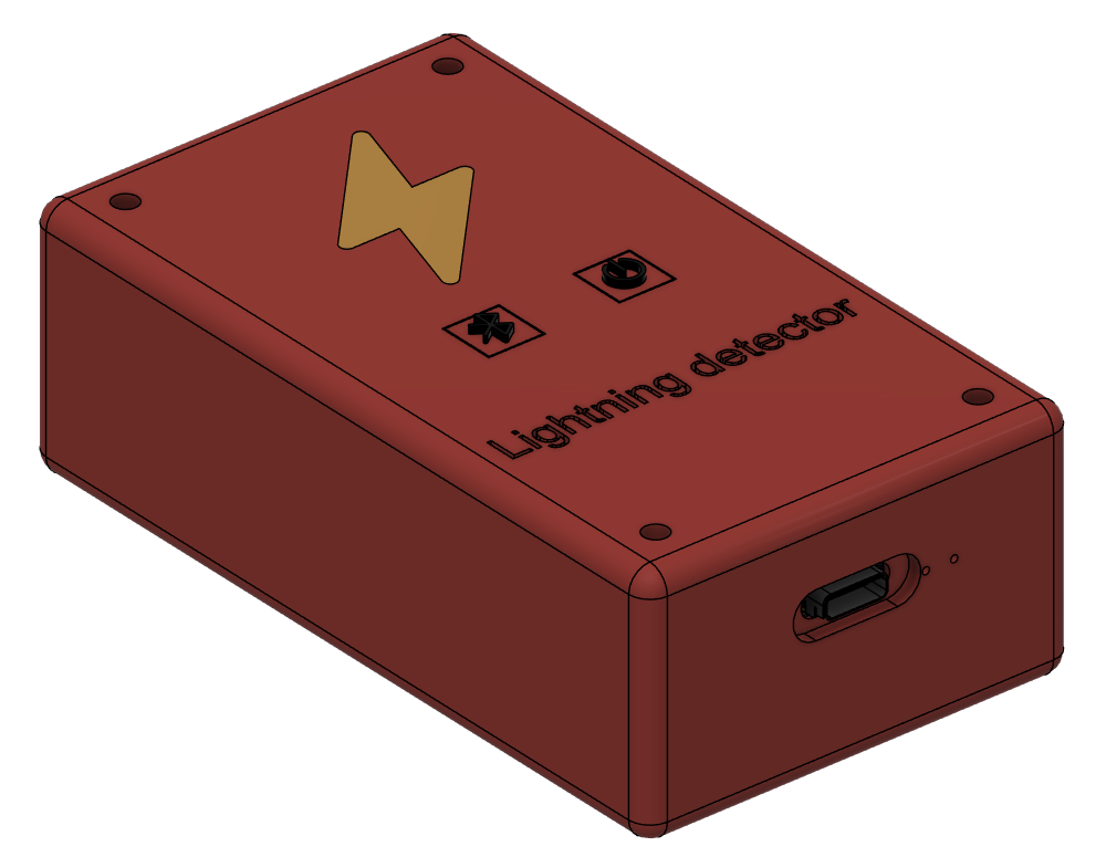
Made in Fusion360
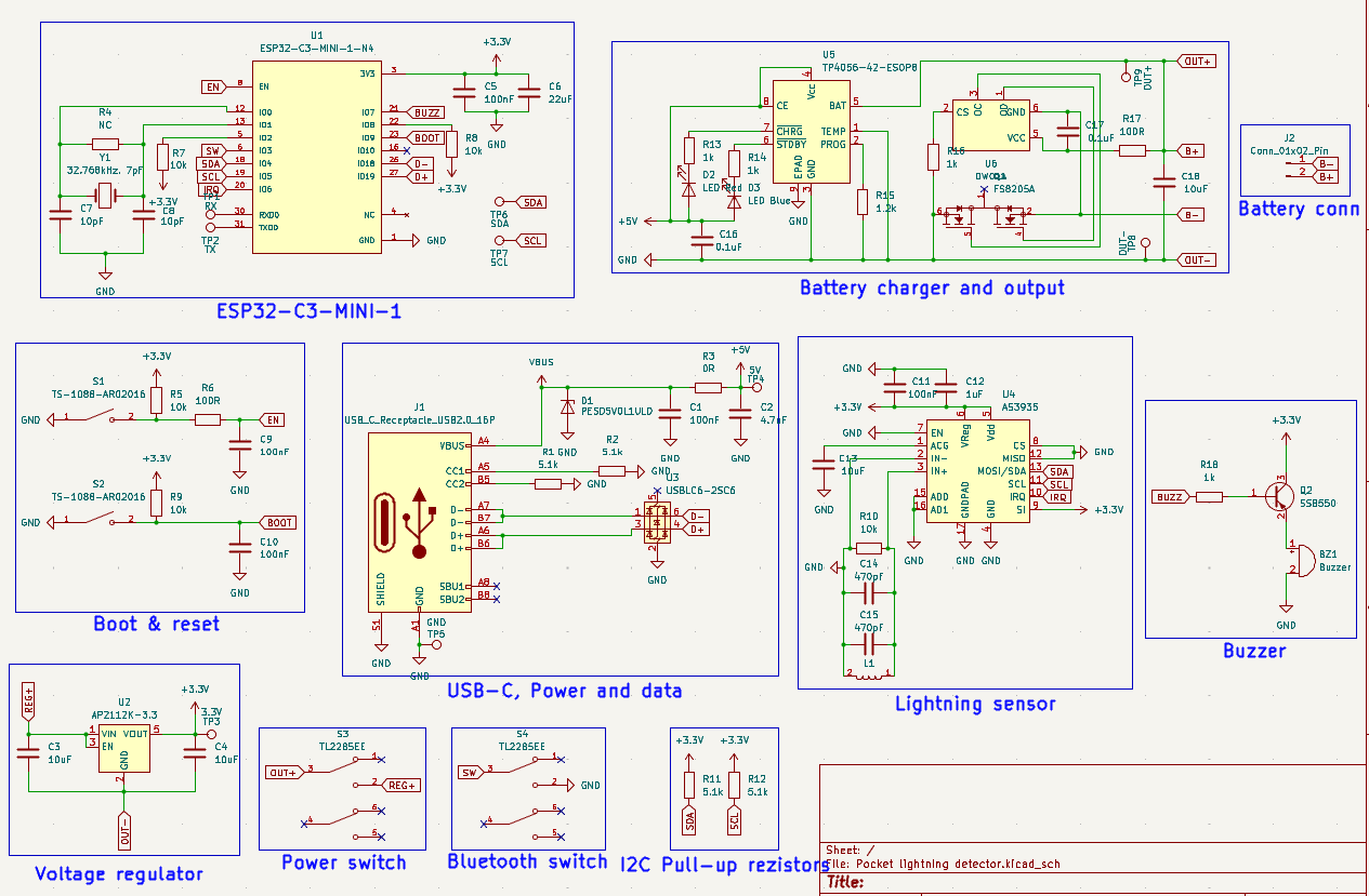
It includes two switches: one to turn on and of the device and other to activate Bluetooth. In the upper right corner, above the USB-C port, are chips for charging, protection, monitoring, and drawing power from the battery, there is also a connector for the battery. The lightning sensor communicates via I2C. The pull-up resistors are located under the ESP-32 near the edge of the PCB. The dimensions of PCB are 99.7 mm x 35 mm.
Schematic
PCB
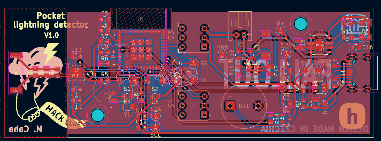
Made in KiCad
⚠️ The area around the lightning sensor antenna must be kept sufficiently far away from metal parts, as there could interfere with the antenna. For this reason, there si no GND copper area around it, and no screws are located nerby.
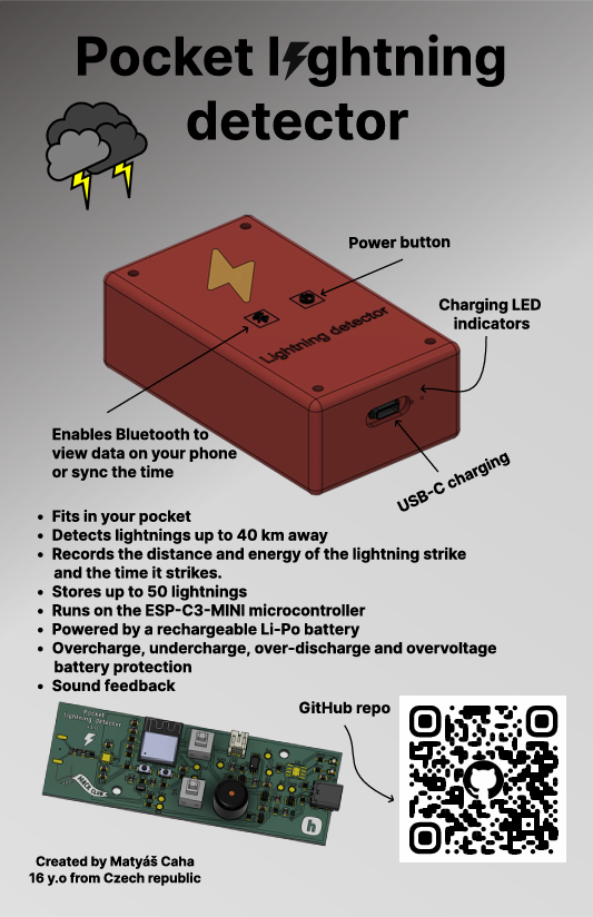
Made in Figma
It uses standard C++ code. One button turns the device on, and the other activates Bluetooth to display lightnings data and synchronize the time. The time must be synchronized every time the device is turned on. Data cen be currently displayed via a serial monitor application. Once the device is connected, it automatically sends lightning data every 3 seconds. Time is synchronized by sending a command, and the board then retrieves the current time. Lightning strikes and the time are stored in RTC memory, so they are erased when the device is turned off. The device runs continuously in deep sleep mode and wakes up only when a lightning strike occurs to save data about the strike and the time it happened, then goes back into deep sleep. RTC memory is the only component that remains active even when the device is in deep sleep mode. The RTC memory stores a maximum of the last 50 lightning strikes to prevent it from becoming overloaded. My goal was to maximize battery life, so I chose Bluetooth over Wi-Fi because Bluetooth is much more power-efficient, and I use deep sleep mode as well (Once the device is finished, I’ll carefully measure its battery life). You can found further details in the comments within the code. After i finished the device, I’ll probably create a nice app where the lightnings will be saved and can be viewed back in time.
You can find it in .csv format here.
This project is licensed under the GNU GPL v3.
Matyas604/Pocket-lightning-detector - Battery-powered Pocket Lightning Detector
Copyright (C) 2026 Matyáš Caha

This program is free software: you can redistribute it and/or modify
it under the terms of the GNU General Public License as published by
the Free Software Foundation, either version 3 of the License, or
(at your option) any later version.

This program is distributed in the hope that it will be useful,
but WITHOUT ANY WARRANTY; without even the implied warranty of
MERCHANTABILITY or FITNESS FOR A PARTICULAR PURPOSE. See the
GNU General Public License for more details.

You should have received a copy of the GNU General Public License
along with this program. If not, see <https://www.gnu.org/licenses/>.
Made with ❤️ by @Matyas604
| Qty | Value | Footprint | References |
|---|---|---|---|
| 7 | LOGO | LOGO | G***, G***, G***, G***, G***, G***, G*** |
| 5 | 10k | Resistor_SMD:R_0805_2012Metric | R5, R7, R8, R9, R10 |
| 4 | 100nF | Capacitor_SMD:C_0805_2012Metric | C5, C9, C10, C11 |
| 4 | 1k | Resistor_SMD:R_0805_2012Metric | R13, R14, R16, R18 |
| 4 | 5.1k | Resistor_SMD:R_0805_2012Metric | R1, R2, R11, R12 |
| 2 | 0.1uF | Capacitor_SMD:C_0805_2012Metric | C16, C17 |
| 2 | 100R | Resistor_SMD:R_0805_2012Metric | R6, R17 |
| 2 | 10uF | Capacitor_SMD:C_0805_2012Metric | C13, C18 |
| 2 | 4.7uF | Capacitor_SMD:C_0805_2012Metric | C3, C4 |
| 2 | 470pF | Capacitor_SMD:C_0805_2012Metric | C14, C15 |
| 2 | 4uF | Capacitor_SMD:C_0805_2012Metric | C1, C2 |
| 2 | TBD | Capacitor_SMD:C_0805_2012Metric | C7, C8 |
| 2 | TL2285EE | footprints:SW_TL2285EE | S3, S4 |
| 2 | TS-1088-AR02016 | footprints:SW_TS-1088-AR02016 | S1, S2 |
| 1 | 0R | Resistor_SMD:R_0805_2012Metric | R3 |
| 1 | 1.2k | Resistor_SMD:R_0805_2012Metric | R15 |
| 1 | 100uH | footprints:MA5532-AE | L1 |
| 1 | 1uF | Capacitor_SMD:C_0805_2012Metric | C12 |
| 1 | 22uF | Capacitor_SMD:C_0805_2012Metric | C6 |
| 1 | 3.3V | TestPoint:TestPoint_Pad_D2.0mm | 3.3V |
| 1 | 5V | TestPoint:TestPoint_Pad_D2.0mm | 5V |
| 1 | AP2112K-3.3 | Package_TO_SOT_SMD:SOT-23-5 | U2 |
| 1 | AS3935 | Package_DFN_QFN:MLPQ-16-1EP_4x4mm_P0.65mm_EP2.8x2.8mm | U4 |
| 1 | Buzzer | Buzzer_Beeper:Buzzer_12x9.5RM7.6 | BZ1 |
| 1 | Conn_01x02_Pin | Connector_JST:JST_PH_S2B-PH-K_1x02_P2.00mm_Horizontal | J2 |
| 1 | Crystal | Crystal:Crystal_SMD_3215-2Pin_3.2x1.5mm | Y1 |
| 1 | DW01A | Package_TO_SOT_SMD:SOT-23-6 | U6 |
| 1 | ESP32-C3-MINI-1-N4 | footprints:XCVR_ESP32-C3-MINI-1-N4 | U1 |
| 1 | FS8205A | footprints:SOP65P640X120-8N | Q1 |
| 1 | GND | TestPoint:TestPoint_Pad_D2.0mm | GND |
| 1 | LED Blue | LED_SMD:LED_0805_2012Metric | D3 |
| 1 | LED Red | LED_SMD:LED_0805_2012Metric | D2 |
| 1 | OUT+ | TestPoint:TestPoint_Pad_D2.0mm | B+ |
| 1 | OUT- | TestPoint:TestPoint_Pad_D2.0mm | GND |
| 1 | PESD5V0L1ULD | Diode_SMD:D_SOD-882D | D1 |
| 1 | RX | TestPoint:TestPoint_Pad_D2.0mm | RX |
| 1 | SCL | TestPoint:TestPoint_Pad_D2.0mm | SCL |
| 1 | SDA | TestPoint:TestPoint_Pad_D2.0mm | SDA |
| 1 | SS8550 | Package_TO_SOT_SMD:SOT-23 | Q2 |
| 1 | TBD | Resistor_SMD:R_0805_2012Metric | R4 |
| 1 | TP4056-42-ESOP8 | Package_SO:SOIC-8-1EP_3.9x4.9mm_P1.27mm_EP2.41x3.3mm_ThermalVias | U5 |
| 1 | TX | TestPoint:TestPoint_Pad_D2.0mm | TX |
| 1 | USBLC6-2SC6 | Package_TO_SOT_SMD:SOT-23-6 | U3 |
| 1 | USB_C_Receptacle_USB2.0_16P | Connector_USB:USB_C_Receptacle_G-Switch_GT-USB-7010ASV | J1 |
The 72 most common of 74 parts.
HYLDAIC/Flagshep-V1_Audio-Player
A high fidelity semi-portable audio player student project with provided PCB files, 3D files and Code

KazimGL/ESP32-PowerIoT-DevBoard
ESP32 battery-powered IoT dev board with Li-ion charging, protection, and sensor support — designed in KiCad


RobbyV2/smart_latch_lock
A self-closing bike lock built as a clamshell ring. A fixed arc bolts to the housing, a hinged arc swings 180 degrees to meet it, and a worm gearmotor closes the loop around the frame and rim on a button press or a BLE…

milovanpms/talk-e
📻 — A simple LoRa-based talkie-walkie built on ESP32, operating on the 433 MHz frequency band for long-range, low-power wireless communication.


AhmedOsama21998/SmartWatch-ESP32-S3-PCB
ESP32-S3 smartwatch PCB with Li-ion battery charging, protection, and power management. Work in progress; sensor integration is planned.
It measures 99.7 × 35 mm and has 2 copper layers, 1.6 mm thick.
74 parts, built around the ESP32-C3-MINI-1-N4, AP2112K-3.3, DW01A and TP4056-42-ESOP8. The full list of its parts is on this page, with links to each part's symbol and footprint where PCBKit's library has them.
From the Matyas604/Pocket-lightning-detector repository on GitHub, at the commit this page was made from: the board is PCB/Pocket lightning detector.kicad_pcb and its schematic PCB/Pocket lightning detector.kicad_sch. PCBKit opens the board in the browser, with nothing to install.
Its repository publishes it under the GPL-3.0 licence: you may reuse it on that licence's terms (keep the author's notice, and for a copyleft licence share your changes alike).