2 layers100.2 × 68.6 mm
Board MKIV
Demetrius-Ross/SimMonitor
Rename the main script to main.py '''bash mv espnowsenderrelay.py main.py '''
45 parts

 Demetrius-Ross/SimMonitor
Rename the main script to main.py '''bash mv espnowsenderrelay.py main.py '''
Schematic Mk2 is an open-source printed circuit board by Demetrius-Ross, from the Demetrius-Ross/SimMonitor repository on GitHub. It is a 2-layer board of 87 × 55.5 mm with 29 parts on 62 nets.
It is built around the REC5A-2405SW/H2/X1, LTV-846S and CR1206-FX-1002ELF, with the CRGH1206J4K7, UHE2A470MPD and DRR3016 among its other parts. Its parts include 16 resistors, 3 capacitors, 2 ICs, 2 connectors and 2 switches. It belongs with the ESP32 and NXP (LPC, Kinetis, i.MX RT) boards of this library.


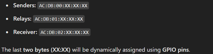
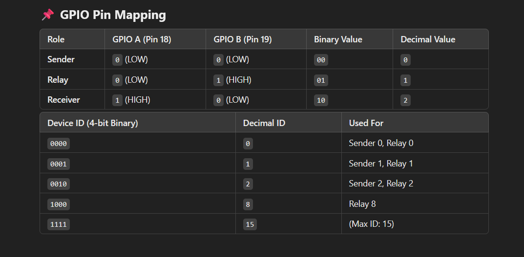
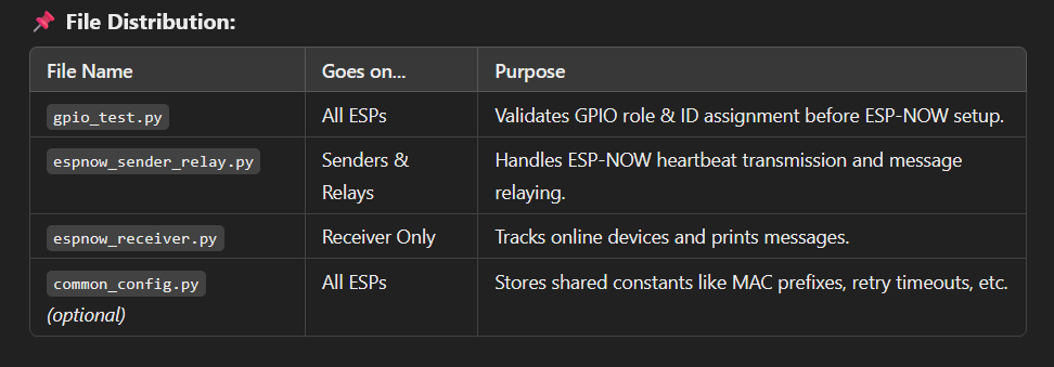
Rename the main script to main.py '''bash mv espnow_sender_relay.py main.py '''
Flash it to the ESP32: '''bash mpremote connect /dev/ttyUSB0 fs cp main.py : '''
Reset the ESP32 to run it automatically: '''bash mpremote connect /dev/ttyUSB0 reset '''
If you want manual execution, you can run any script interactively: '''bash mpremote connect /dev/ttyUSB0 run gpio_test.py '''
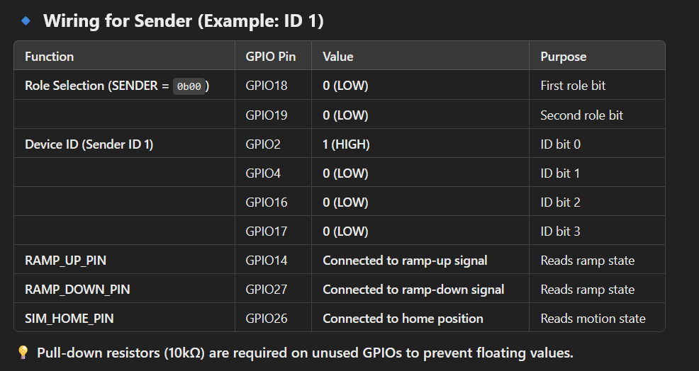
Below is a quick reference for how to wire GPIO17, GPIO16, GPIO4, and GPIO2 to assign a device ID (0–15). Each pin is interpreted as a bit in the 4-bit ID, read in the order (Pin2=bit0, Pin4=bit1, Pin16=bit2, Pin17=bit3).
| Device ID | Binary (bit3..bit0) | Pin17 (bit3) | Pin16 (bit2) | Pin4 (bit1) | Pin2 (bit0) |
|---|---|---|---|---|---|
| 0 | 0000 | 0 (LOW) | 0 (LOW) | 0 (LOW) | 0 (LOW) |
| 1 | 0001 | 0 (LOW) | 0 (LOW) | 0 (LOW) | 1 (HIGH) |
| 2 | 0010 | 0 (LOW) | 0 (LOW) | 1 (HIGH) | 0 (LOW) |
| 3 | 0011 | 0 (LOW) | 0 (LOW) | 1 (HIGH) | 1 (HIGH) |
| 4 | 0100 | 0 (LOW) | 1 (HIGH) | 0 (LOW) | 0 (LOW) |
| 5 | 0101 | 0 (LOW) | 1 (HIGH) | 0 (LOW) | 1 (HIGH) |
| 6 | 0110 | 0 (LOW) | 1 (HIGH) | 1 (HIGH) | 0 (LOW) |
| 7 | 0111 | 0 (LOW) | 1 (HIGH) | 1 (HIGH) | 1 (HIGH) |
| 8 | 1000 | 1 (HIGH) | 0 (LOW) | 0 (LOW) | 0 (LOW) |
| 9 | 1001 | 1 (HIGH) | 0 (LOW) | 0 (LOW) | 1 (HIGH) |
| 10 | 1010 | 1 (HIGH) | 0 (LOW) | 1 (HIGH) | 0 (LOW) |
| 11 | 1011 | 1 (HIGH) | 0 (LOW) | 1 (HIGH) | 1 (HIGH) |
| 12 | 1100 | 1 (HIGH) | 1 (HIGH) | 0 (LOW) | 0 (LOW) |
| 13 | 1101 | 1 (HIGH) | 1 (HIGH) | 0 (LOW) | 1 (HIGH) |
| 14 | 1110 | 1 (HIGH) | 1 (HIGH) | 1 (HIGH) | 0 (LOW) |
| 15 | 1111 | 1 (HIGH) | 1 (HIGH) | 1 (HIGH) | 1 (HIGH) |
role_value = 0 => "SENDER".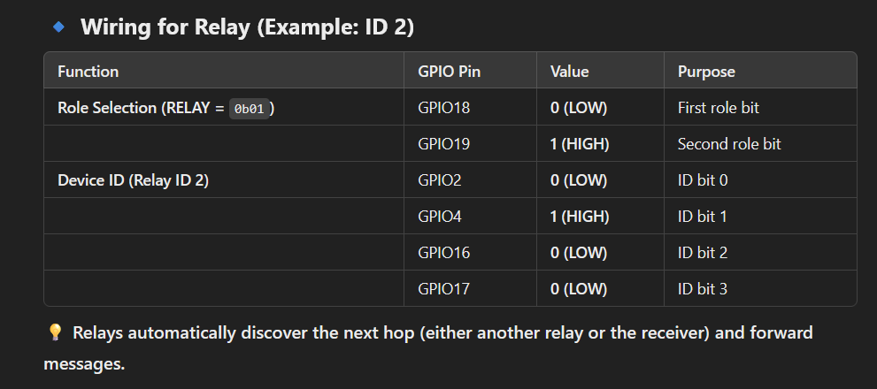
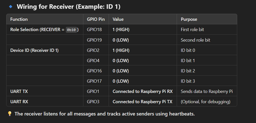
| Qty | Value | Footprint | References |
|---|---|---|---|
| 8 | CR1206-FX-1002ELF | footprints:RESC3216X75N | R5, R6, R7, R8, R9, R15, R16, R17 |
| 7 | CRGH1206J4K7 | footprints:RESC3115X65N | R1, R2, R3, R10, R11, R12, R13 |
| 2 | UHE2A470MPD | footprints:PCAP_10x12_5-THRU-ELECT_NCA | C1, C2 |
| 2 | ~ | footprints:PTC_RESET_FUSE | RF1, RF2 |
| 1 | 1000pf/3kV | footprints:CAPC3216X180N | C3 |
| 1 | 1757255 | footprints:PHOENIX_1757255 | J2 |
| 1 | A-DF_09_A_KG-T4S | footprints:ASSMANN_A-DF_09_A_KG-T4S | J1 |
| 1 | CRGH1206J4K7 | footprints:RESC3015X65N | R4 |
| 1 | DRR3016 | footprints:DRR3010 | S1 |
| 1 | ESP32-DEVKITC-32D | footprints:MODULE_ESP32-DEVKITC-32D | U1 |
| 1 | LTV-846S | footprints:SOIC254P1016X460-16N | U2 |
| 1 | On/Off Switch | Button_Switch_SMD:Panasonic_EVQPUJ_EVQPUA | SW1 |
| 1 | REC5A-2405SW_H2 | footprints:CONV_REC5A-2405SW_H2 | PS1 |
| 1 | SS34B-HF | footprints:DO214AASMB_CIP-L | D1 |
It measures 87 × 55.5 mm and has 2 copper layers, 1.6 mm thick.
29 parts, built around the REC5A-2405SW/H2/X1, LTV-846S, CR1206-FX-1002ELF and CRGH1206J4K7. The full list of its parts is on this page, with links to each part's symbol and footprint where PCBKit's library has them.
From the Demetrius-Ross/SimMonitor repository on GitHub, at the commit this page was made from: the board is Hardware-Design/board_design_legacy/schematic_Mk2.kicad_pcb and its schematic Hardware-Design/board_MKIV/ESP-Board.kicad_sch. PCBKit opens the board in the browser, with nothing to install.
Its repository states no licence, so its author keeps all rights: ask Demetrius-Ross before reusing the design.
Demetrius-Ross/SimMonitor
Rename the main script to main.py '''bash mv espnowsenderrelay.py main.py '''

Demetrius-Ross/SimMonitor
Rename the main script to main.py '''bash mv espnowsenderrelay.py main.py '''

Demetrius-Ross/SimMonitor
Rename the main script to main.py '''bash mv espnowsenderrelay.py main.py '''

Demetrius-Ross/SimMonitor
Rename the main script to main.py '''bash mv espnowsenderrelay.py main.py '''

Demetrius-Ross/SimMonitor
Rename the main script to main.py '''bash mv espnowsenderrelay.py main.py '''

OE1KHZ/SlidersOfSociety-PCB
A CANbus controlled closed loop motor fader module based on Microchip's PIC18F25K83


JGilcreast/MetalHead
An opensource firmware and software drop-in replacement for the 85V Automatic Stirrup Bender by CRS Specialties Inc. ...short story behind the name...


gusmanb/logicanalyzer
24 channel, 100Msps logic analyzer hardware and software

VoronDesign/Voron-Hardware
Cool Hardware designed by the Voron Design group

hoglet67/RGBtoHDMI
Bare-metal Raspberry Pi project that provides pixel-perfect sampling of Retro Computer RGB/YUV video and conversion to HDMI