
2 layers272.5 × 12 mm
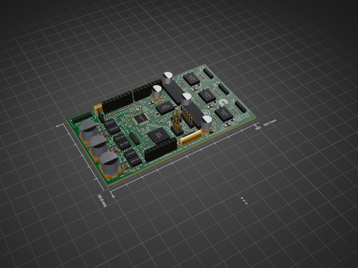
 Defdist/GrBLDC330
Uno Shield for grblDD: closed loop spindle VFD + 4 stepper drivers
GrBLDC is an open-source printed circuit board by Defdist, from the Defdist/GrBLDC3 repository on GitHub. It is a 6-layer board of 103.1 × 59.6 mm with 212 parts on 159 nets, routed with 3,426 tracks and 343 vias.
It is built around the ATMEGA16M1-AU and DRV8818. Its parts include 84 capacitors, 84 resistors, 20 connectors, 6 ICs and 6 transistors. It belongs with the AVR (ATmega, ATtiny) boards of this library.
Uno Shield for grblDD: closed loop spindle VFD + 4 stepper drivers
Main Controller PCB for GG3. Hardware version 3B This is the 1st PCB shipped in GG3.
PCB designed in KiCAD.
Changes (from the previous prototype PCB):
-3-pin header order changed from VGS to VSG (e.g. from +-X to +X-). This creates an incompatibility issue with GG2 units, which will require a pin swap.
-Removed Door Switch (which also restored previous gap for zip tie).
-Vref changed to 1.78 volts (added 1k series with pulldown).
-Added two additional stepper power modes, to reduce power consumption at idle, and to (briefly) increase power if X axis is binding, or if BLDC controller is bogged down in a corner.
-Stepper X1 is now disabled unless A0_STEP_X1_EN is pulled high... this pin is shared with 64M1 reset, which means that when the X1 stepper (only) is disabled, the spindle will not spin.
-Replaced 2x1 screw terminal probe connector with 5x1 SIP. This is now the only wire harness that goes to LED PCB. 24V and 5V are current limited on this PCB, so that metal chips contacting LED PCB don't affect GrBLDC.
-Added Zener protection diode to 5V rail, in the hope that if 24V finds its way onto that rail, the zener will short it out... this will of course burn out the zener, but hopefully by then the PTC on the Uno will have opened.
-Fixed incorrect pinout on A4910 (pins 39 & 40 swapped).
-BLDC Hall connector changed from 1x5 to 2x3, to make assembling easier. 6th pin is now connected to spindle wipers.
-Removed 2x3 64M1 programming header; connected SPI to Arduino pins instead. 328p can now program this part in-situ (via temporarily loading SPI bitbang firmware onto 328p).
-Emergency stop now pulls BLDC and stepper drivers into reset.
-Emergency stop interface to 328p fixed, such that computer can now pulse reset line during firmware updates. When estop enabled, 328p continuously held in reset.
-Z stepper connector changed to 2x2, so that it fits through gantry bushings.
-24V/GND/GND 45 degree connector now fits (moved fan connector and capacitors).
New Parts:
LED PCB:
102-5777-ND
Get longer right angle SIPs for LED PCB
LED - 732-5660-1-ND
| Qty | Value | Footprint | References |
|---|---|---|---|
| 43 | 220n | Capacitors_SMD:C_0603 | C1, C2, C14, C15, C16, C17, C18, C19, C20, C21, C22, C23, C24, C25, C26, C27 +27 |
| 15 | 10u | Capacitors_SMD:C_1206 | C44, C49, C52, C53, C54, C55, C56, C59, C60, C61, C62, C64, C65, C66, C89 |
| 14 | 1.47k | Resistors_SMD:R_0603 | R1, R2, R20, R29, R33, R34, R53, R61, R76, R77, R78, R79, R80, R81 |
| 13 | 47 | Resistors_SMD:R_0603 | R23, R39, R41, R42, R44, R46, R47, R48, R52, R64, R68, R70, R72 |
| 11 | 680p | Capacitors_SMD:C_0603 | C6, C7, C8, C9, C10, C11, C12, C13, C84, C85, C86 |
| 10 | 56k | Resistors_SMD:R_0603 | R3, R4, R5, R6, R7, R8, R9, R10, R21, R22 |
| 8 | 0.09 | Resistors_SMD:R_1206 | R11, R12, R13, R14, R15, R16, R17, R18 |
| 7 | 1k | Resistors_SMD:R_0603 | R19, R25, R26, R27, R30, R31, R32 |
| 7 | 1k | Resistor_SMD:R_0603_1608Metric | R54, R55, R56, R59, R60, R63, R83 |
| 6 | 24.3k | Resistors_SMD:R_0603 | R67, R69, R71, R73, R74, R75 |
| 6 | 33n | Capacitors_SMD:C_0603 | C45, C46, C47, C48, C50, C79 |
| 6 | 470k | Resistors_SMD:R_0603 | R40, R43, R45, R49, R50, R51 |
| 6 | DNP | Resistors_SMD:R_0603 | R24, R28, R35, R36, R37, R66 |
| 6 | IRF5406 | A3938:IRF5406 | Q1, Q2, Q3, Q4, Q5, Q6 |
| 4 | 100u | A3938:c_elec_493-3953-2-ND_6.3x7.7 | C68, C69, C70, C71 |
| 4 | DRV8818 | DRV8818:DRV8818 | U1, U2, U3, U4 |
| 3 | .005 | Resistors_SMD:R_1206 | R38, R57, R58 |
| 3 | 330u | Capacitors_SMD:c_elec_10x10.5 | C51, C57, C63 |
| 3 | CONN_01X04 | A3938:Pin_A98335-ND_1x04 | P3, P6, P7 |
| 3 | CONN_8 | A3938:ARDUINO-SIL-8 | P2, P9, P10 |
| 3 | Fiducial | Fiducial:Fiducial_0.5mm_Mask1mm | FID1, FID2, FID3 |
| 2 | 1.47k | Resistor_SMD:R_0603_1608Metric | R82, R84 |
| 2 | 12p | Capacitors_SMD:C_0603 | C36, C39 |
| 2 | 6V Zener | Diode_SMD:D_SOD-123 | D2, D3 |
| 2 | DNP | Resistor_SMD:R_0603_1608Metric | R62, R65 |
| 2 | Heat_Sink | A3938:HeatSink | HS1, HS2 |
| 1 | 0 | ILTC:ILTC | ILTC1 |
| 1 | 16M | Crystals:Crystal_SMD_2016-4pin_2.0x1.6mm | Y1 |
| 1 | 4910SCK | TestPoint:TestPoint_Pad_D1.0mm | J2 |
| 1 | 4910SDI | TestPoint:TestPoint_Pad_D1.0mm | J3 |
| 1 | 4910SDO | TestPoint:TestPoint_Pad_D1.0mm | J4 |
| 1 | 4910STR | TestPoint:TestPoint_Pad_1.0x1.0mm | J5 |
| 1 | A4910 | A3938:A4910-LQFP_48 | U5 |
| 1 | ATMEGA16M1-A | Housings_QFP:TQFP-32_7x7mm_Pitch0.8mm | IC1 |
| 1 | CONN_01X03 | Custom Footprints:277-1722-ND | P12 |
| 1 | CONN_01X03 | Connector_PinHeader_2.54mm:PinHeader_1x03_P2.54mm_Vertical | P4 |
| 1 | CONN_01X03 | Socket_Strips:Socket_Strip_Straight_1x03 | P15 |
| 1 | CONN_01X03 | Custom Footprints:Pin_Header_277-1578-ND_3x01 | P14 |
| 1 | CONN_01X05 | Connector_PinHeader_2.54mm:PinHeader_1x05_P2.54mm_Vertical | P5 |
| 1 | CONN_2 | A3938:SIL-2 | P11 |
| 1 | CONN_6 | A3938:ARDUINO-SIL-6 | P1 |
| 1 | CONN_9 | A3938:SIL-9 | P8 |
| 1 | Conn_02x02_Top_Bottom | Connector_PinHeader_2.54mm:PinHeader_2x02_P2.54mm_Vertical | J6 |
| 1 | Conn_02x03_Odd_Even | Connector_PinHeader_2.54mm:PinHeader_2x03_P2.54mm_Vertical | J1 |
| 1 | LM4040 | A3938:SOT-23 | D1 |
| 1 | LOGO | Custom Footprints:DD Logo | G*** |
The 211 most common of 212 parts.


claudiucherciu/CANtoUART
ATmega16M1 with 2CAN transceivers and UART breakout on a PC104 pcb.


brandon-martinez/jgb
The microcontroller present on this board, and the software which runs on it should eventually be integrated into each node which must communicate via the CAN bus.


lindamao-waterloop/waterloop_electrical
Version control for the Waterloop Electrical Team

ahmadexp/Open-Source-PC110
Figuring out the missing technical documentation of the beloved PC110
It measures 103.1 × 59.6 mm and has 6 copper layers, 1.6 mm thick.
212 parts, built around the ATMEGA16M1-AU and DRV8818. The full list of its parts is on this page, with links to each part's symbol and footprint where PCBKit's library has them.
From the Defdist/GrBLDC3 repository on GitHub, at the commit this page was made from: the board is GrBLDC V3.2/PCB/GrBLDC.kicad_pcb. PCBKit opens the board in the browser, with nothing to install.
Its repository states no licence, so its author keeps all rights: ask Defdist before reusing the design.