2 layers96.6 × 100 mm

 dduarteCE/Robot-vacuum1
Embedded Linux robotic vacuum system built with Yocto on Raspberry Pi 4, featuring autonomous navigation, audio playback, and remote control through a web interface.
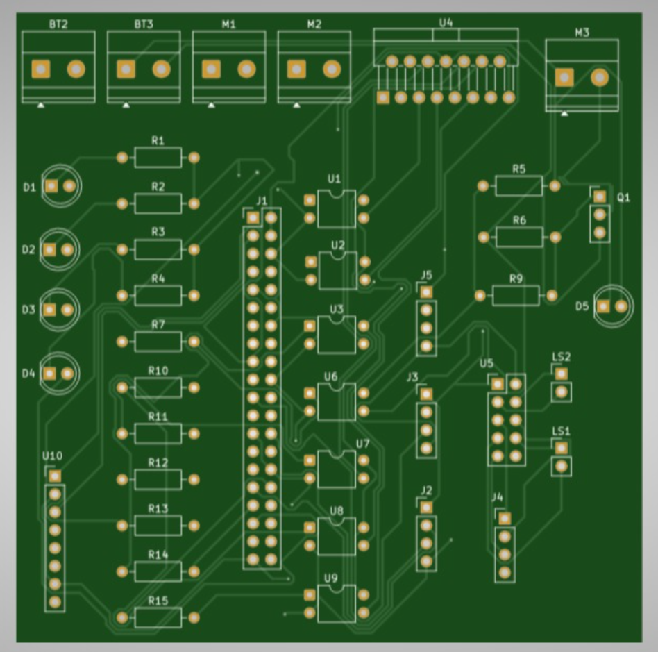
SchematicKiCadProyect is an open-source printed circuit board by dduarteCE, from the dduarteCE/Robot-vacuum repository on GitHub, published under the MIT licence. It is a 2-layer board of 99.5 × 99.5 mm with 42 parts on 72 nets, routed with 415 tracks and 36 vias.
It is built around the L298N, PAM8403DR and MPU-6050, with the HC-SR04 and FDMS8350LET40 among its other parts. Its parts include 14 resistors, 10 ICs, 5 diodes, 5 connectors and 1 transistor. It belongs with the audio and music and computers and single-board computers boards of this library.


This repository contains the complete system for an autonomous robot vacuum built on a Raspberry Pi 4, using a custom Linux image created with Yocto. The system includes autonomous navigation, low-level hardware control, a secure web interface for remote control, and audio playback.
For a detailed description of the software design and Yocto image decisions, see the Design Document (DI). For a summary of the technologies used, see the Continuous Learning Document (AC).
librobot.so)| Feature | Description |
|---|---|
| Autonomous Cleaning | Reactive zig-zag coverage algorithm with alternating turn direction. |
| Manual Control | Directional D-pad control via HTTPS, with ventilator activation/deactivation. |
| Web Interface | Dashboard with registration, login, remote control, coverage map, and music player. |
| HTTPS Security | Self-signed certificate automatically generated on first boot. |
| Authentication | Passwords hashed with SHA-256 (10,000 iterations) and salt, with session management via cookies. |
| Inertial Sensor (IMU) | MPU-6050 for orientation tracking and accelerometer-based motion detection. |
| 2D Mapping | 64x64 fixed grid that records detected obstacles with awareness of the robot's orientation. |
| Audio | Music player and synthesized notification tones for system events. |
| Automatic Startup | The system starts automatically on boot thanks to a SysVinit script in the Yocto image. |
The robot is built around a Raspberry Pi 4 running a minimal, custom Linux image.
For a complete breakdown of components and GPIO mapping, see the hardware documentation. Evidence of the cross-compilation can be found in the yocto-image-recipies/evidence/ directory.
The application uses a multi-threaded architecture for concurrent, real-time control.
main thread ──► web subsystem (libmicrohttpd + GnuTLS)
                 │
                 └── MHD-single — handles all HTTP requests on a
                                  single internal thread (lock-free handlers)

background pthreads:
├── sensor        — 20 Hz (ultrasonics) + 100 Hz (IMU) + speed integration
├── navigation    — 100 Hz (motor/LED control, pose integration, autonomous FSM)
├── map           — 10 Hz (2D grid update with obstacle projection)
└── audio         — 10 Hz (playback state + notification tones)
Inter-thread communication is done via seqlock-based snapshots, which allow lock-free reads from multiple threads and writes from a single thread per state slot. This design avoids shared critical sections between real-time threads.
| Layer | Component | Role |
|---|---|---|
| HTTP(S) Server | libmicrohttpd | Embedded server daemon to handle REST API requests. |
| Security Layer | GnuTLS | Provides TLS/SSL encryption for HTTPS communication. |
| Authentication | Authentication Module | Manages password hashing (SHA-256 with salt) and user storage. |
| Session Management | Session Module | Manages in-memory session tokens with an inactivity timeout. |
| Frontend | HTML, CSS, JS | User interface rendered in the browser, which consumes the robot's REST API. |
The operating system is a custom Linux image built with Yocto (version Scarthgap 5.0.15).
core-image-minimal for a minimal resource footprint.raspberrypi4.meta-raspberrypi: Base support for the Raspberry Pi.meta-rpi4-config: Specific configuration for the RPi4 (e.g., WiFi).meta-robot: Recipe to compile and install the robot application.SysVinit, with a script to launch the robot application on boot.The build process is done in two main phases: building the Yocto image and cross-compiling the application.
bitbake is used to build the operating system image and the cross-compilation SDK.
# 1. Initialize the Yocto environment
source oe-init-build-env rpi4

# 2. Add the necessary layers
bitbake-layers add-layer ...

# 3. Build the image
bitbake core-image-minimal

# 4. Build the SDK
bitbake core-image-minimal -c populate_sdkOnce the SDK is installed, the robot application can be compiled.
# 1. Load the SDK environment
. /opt/poky/5.0.15/environment-setup-cortexa7t2hf-neon-vfpv4-poky-linux-gnueabi

# 2. Use CMake to compile the project
cd robot-6.0.1 && mkdir build && cd build
cmake ../
make && make install
For more details on the build process, see the Yocto build notes.
librobot.so)The core of the system is encapsulated in the librobot.so dynamic library, which provides a C API to control all the robot's hardware. Below is a summary of its functionality, based on the robot_test.c test program.
| Module | Main Functions | Description |
|---|---|---|
| Ventilator | ventilator_on(), ventilator_off() | Controls the vacuum motor. |
| LEDs | led_blink(led_num, duration_ms) | Allows individual blinking of the status LEDs. |
| Ultrasonic Sensors | ultrasonic_get_distance_cm(sensor_num) | Gets the distance in centimeters from one of the three HC-SR04 sensors. |
| Motors | motor_set_speed(motor_num, speed), motor_set_direction(motor_num, dir), motor_stop(motor_num), motor_brake(motor_num) | Provides full control over the wheel motors, including speed (0-100%), direction (forward, backward), stop, and active brake. |
| IMU (MPU-6050) | mpu6050_read_accel(mpu, &ax, &ay, &az), mpu6050_read_gyro(mpu, &gx, &gy, &gz) | Reads raw accelerometer and gyroscope data from the IMU sensor via the I2C bus. |
| Audio | audio_play_file(filepath), audio_pause(), audio_resume(), audio_stop(), audio_set_volume(vol_percent) | Manages the playback of MP3 audio files, allowing pause, resume, stop, and volume adjustment. |
Architecture Diagrams: The original hardware and software architecture diagrams are located in docs/InitialPlanOfDevelopment.pdf. Although some details may have evolved, they provide a good overview of the conceptual design.
Compilation Evidence: Logs and artifacts demonstrating the cross-compilation process with Yocto are located in the yocto-image-recipies/evidence/ directory.
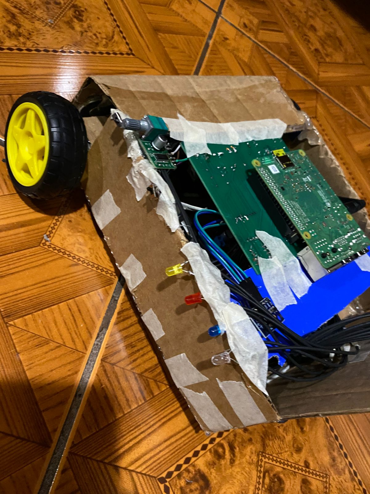
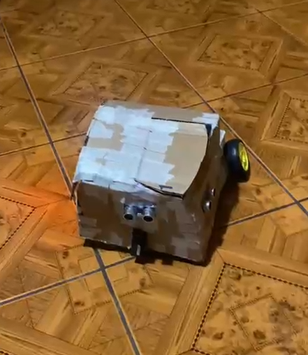
Project Progress Images: Below are some images that document the development and status of the project:
Image of the initial prototype on the breadboard:
PCB design in KiCad:
Assembled and running robot:
| Qty | Value | Footprint | References |
|---|---|---|---|
| 11 | 220 | Resistor_THT:R_Axial_DIN0207_L6.3mm_D2.5mm_P10.16mm_Horizontal | R1, R2, R3, R4, R7, R10, R11, R12, R13, R14, R15 |
| 7 | PC817 | Package_DIP:DIP-4_W7.62mm | U1, U2, U3, U6, U7, U8, U9 |
| 4 | LED | LED_THT:LED_D5.0mm | D1, D2, D3, D4 |
| 3 | HC-SR04 | Connector_PinHeader_2.54mm:PinHeader_1x04_P2.54mm_Vertical | J2, J3, J5 |
| 2 | Battery_Cell | TerminalBlock_Phoenix:TerminalBlock_Phoenix_MKDS-1,5-2_1x02_P5.00mm_Horizontal | BT2, BT3 |
| 2 | Motor_DC | TerminalBlock_Phoenix:TerminalBlock_Phoenix_MKDS-1,5-2_1x02_P5.00mm_Horizontal | M1, M2 |
| 2 | Speaker | Connector_PinHeader_2.54mm:PinHeader_1x02_P2.54mm_Vertical | LS1, LS2 |
| 1 | 100 | Resistor_THT:R_Axial_DIN0207_L6.3mm_D2.5mm_P10.16mm_Horizontal | R9 |
| 1 | 10K | Resistor_THT:R_Axial_DIN0207_L6.3mm_D2.5mm_P10.16mm_Horizontal | R6 |
| 1 | 4.7K | Resistor_THT:R_Axial_DIN0207_L6.3mm_D2.5mm_P10.16mm_Horizontal | R5 |
| 1 | 5020 Centrifugal Blower | TerminalBlock_Phoenix:TerminalBlock_Phoenix_MKDS-1,5-2_1x02_P5.00mm_Horizontal | M3 |
| 1 | AudioJack_TRRS | Connector_PinHeader_2.54mm:PinHeader_1x04_P2.54mm_Vertical | J4 |
| 1 | D | LED_THT:LED_D5.0mm | D5 |
| 1 | FDMS8350LET40 | Connector_PinHeader_2.54mm:PinHeader_1x03_P2.54mm_Vertical | Q1 |
| 1 | L298N | Package_TO_SOT_THT:TO-220-15_P2.54x5.08mm_StaggerOdd_Lead4.58mm_Vertical | U4 |
| 1 | MPU-6050 | Connector_PinHeader_2.54mm:PinHeader_1x08_P2.54mm_Vertical | U10 |
| 1 | PAM8403D | Connector_PinHeader_2.54mm:PinHeader_2x05_P2.54mm_Vertical | U5 |
| 1 | Raspberry_Pi_4 | Connector_PinHeader_2.54mm:PinHeader_2x20_P2.54mm_Vertical | J1 |

Crem2y/pico-console-v2-pcb
pico console v2 board (firmware : https://github.com/Crem2y/pico-console-v2)

Mohamed-Adel-ELshiemy/PCB
DC motor PCB Design with all files needed and make my foot print from scratch

omersoner-dev/SPECTRODRIVE
Light-following robot with PCB design, sensor integration, and Bluetooth control

ErickMorales1312/Proyecto-IMTC
IoT project for Autonomous Firefighting and Fire Detection System


Darshan7052006/PCB-Design-Projects
Collection of PCB designs created using KiCad. Includes power supplies, embedded systems, sensor boards, and hardware projects with schematics, PCB layouts, manufacturing files, and documentation.
It measures 99.5 × 99.5 mm and has 2 copper layers, 1.6 mm thick.
42 parts, built around the L298N, PAM8403DR, MPU-6050 and HC-SR04. The full list of its parts is on this page, with links to each part's symbol and footprint where PCBKit's library has them.
From the dduarteCE/Robot-vacuum repository on GitHub, at the commit this page was made from: the board is docs/SchematicKiCadProyect/Schematic.kicad_pcb and its schematic docs/SchematicKiCadProyect/Schematic.kicad_sch. PCBKit opens the board in the browser, with nothing to install.
Its repository publishes it under the MIT licence: you may reuse it on that licence's terms (keep the author's notice, and for a copyleft licence share your changes alike).