QUT Autopilot Pixracer
Heckus/QUT-OpenFCU
The primary objective is to create an alternative to the difficult-to-source off-the-shelf Pixhawk 6. This work builds upon a edited pixracer version produced by KAI (Wesley) in 2022.

Open-source three-phase ESC hardware designed in KiCad to study ESC operation
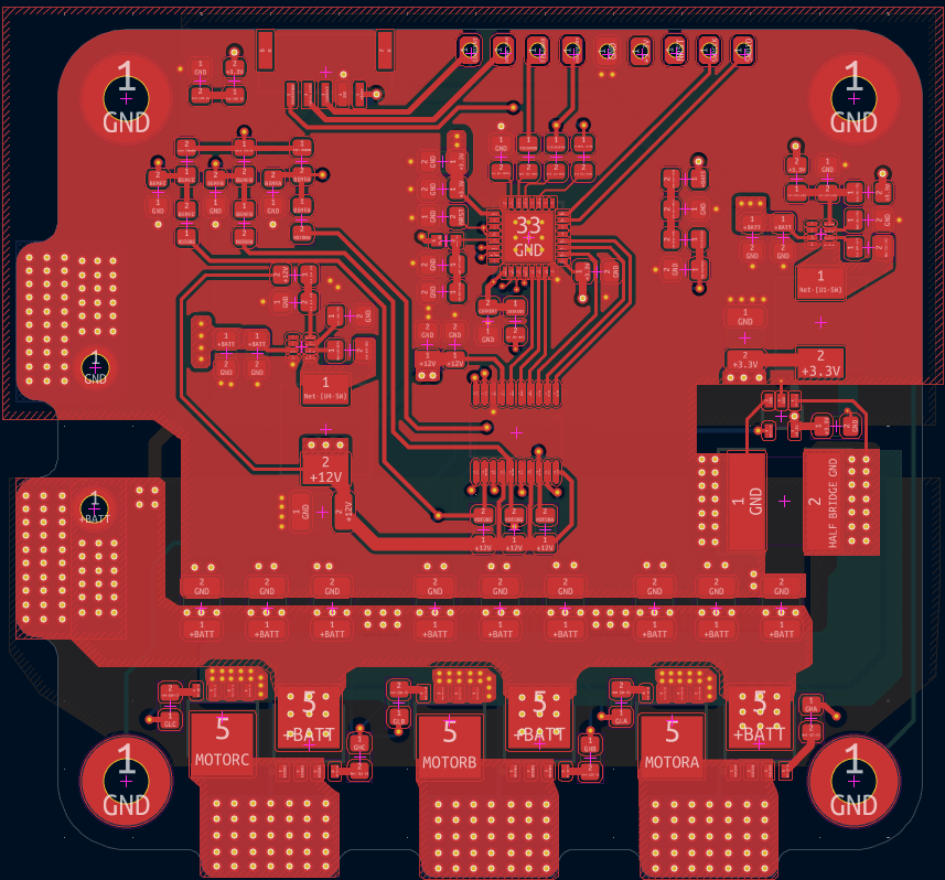
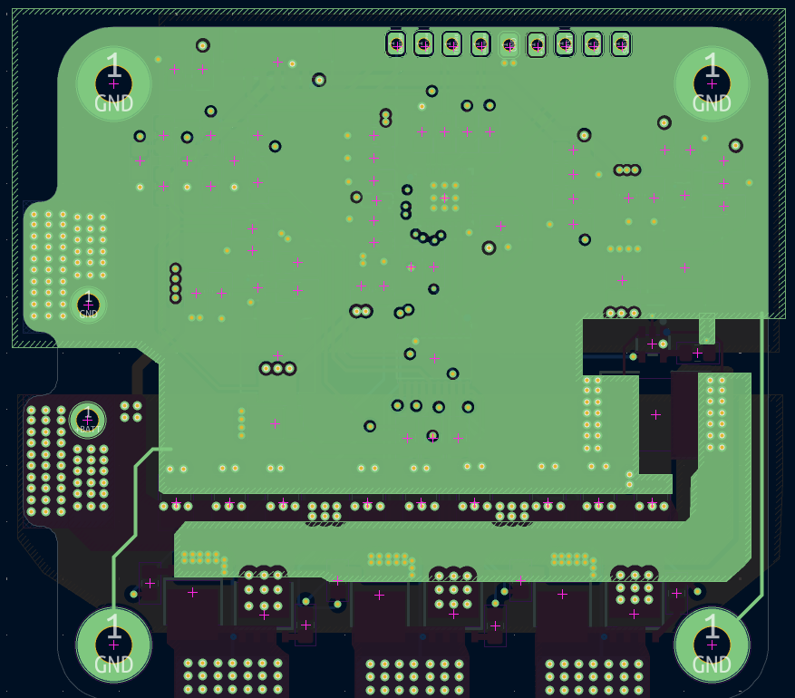
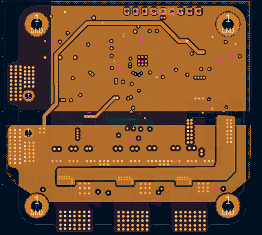
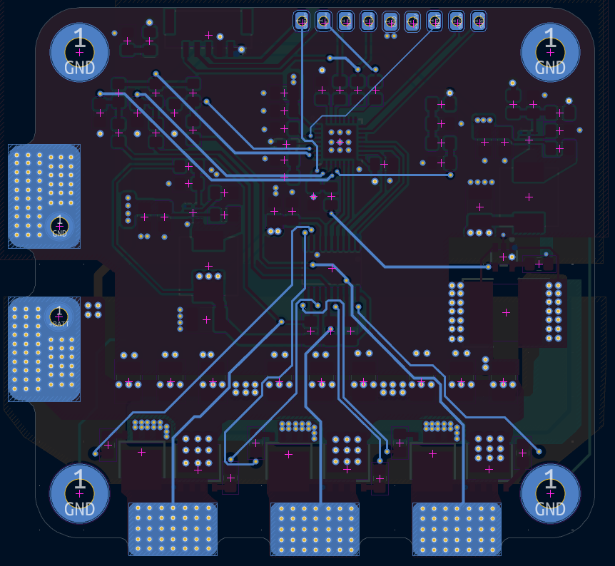
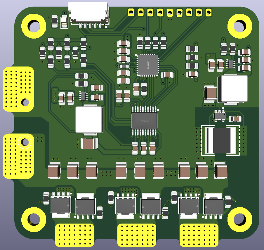
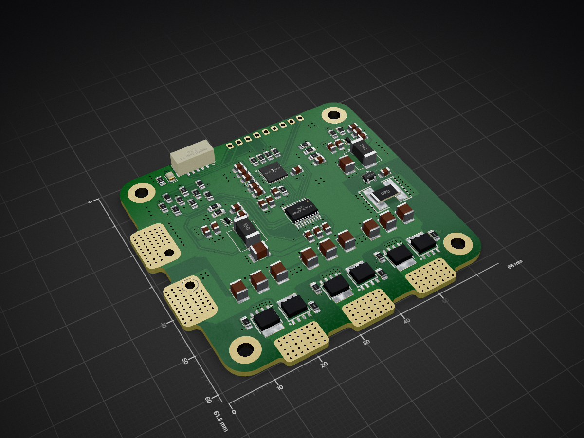
STM32F051-ESC is an open-source printed circuit board by Datnewlevel, from the Datnewlevel/STM32F051-ESC repository on GitHub. It is a 4-layer board of 66 × 61.8 mm with 94 parts on 68 nets, routed with 407 tracks and 507 vias.
It is built around the STM32F051K8U7, DRV8300DPWR-MS and SM05B-GHS-TB(LF)(SN), with the PSMN1R4-40YLDX-VB, MDA7030-150M and PSPMAA0603-8R2M-ANF among its other parts. Its parts include 34 capacitors, 29 resistors, 6 ICs, 6 transistors and 2 inductors. It belongs with the robots and motor control boards and the STM32 boards of this library.
An open-source hardware learning project for a three-phase electronic speed controller (ESC), designed in KiCad. I created this schematic and PCB while studying existing ESC circuits shared online to understand how their power supply, gate driver, motor bridge, and sensing stages work together.
This is the first PCB revision. I am currently ordering the board for fabrication; the hardware has not yet been assembled or tested.
The design combines a microcontroller, a three-phase gate driver, six power MOSFETs, and voltage and current sensing on a four-layer PCB. The schematic labels the intended battery input range as 14-25 V. This range is a design target, not a verified operating specification.
The main parts are:
| Function | Component |
|---|---|
| Microcontroller | STM32F051K8U7 |
| Three-phase gate driver | DRV8300DPWR |
| Motor bridge | Six PSMN1R4-40YLDX-VB MOSFETs |
| 3.3 V and 12 V supplies | Two TPS62932DRLR buck converters |
| Current measurement | INA180B2IDBVT amplifier and a 1 mΩ shunt |
The schematic also includes back-EMF sensing for the three motor phases, SWD programming pads, a signal input, telemetry connections, and test pads.
The full schematic is available as a PDF. It is divided into the power supplies, microcontroller, gate driver, back-EMF sensing, MOSFET bridge, connectors, and current-sensing sections.
The board is approximately 66.05 × 61.80 mm, with four copper layers and a 1.6 mm board thickness in the KiCad project.


| File / Folder | Description |
|---|---|
test.kicad_pro | Main KiCad project settings |
test.kicad_sch | Single ESC schematic source |
test.kicad_pcb | Four-layer PCB layout source |
ESC_PCB/ | Schematic PDF and PCB images |
production/bom.csv | Generated bill of materials |
production/positions.csv | Generated component placement data |
production/designators.csv | Generated designator list |
production/netlist.ipc | Generated IPC netlist |
production/test.zip | Generated Gerber and drill files |
test/ | A separate KiCad experiment; it is not part of the ESC design |
The PCB is being ordered for the first prototype. Assembly, power-up checks, firmware, and motor testing are still pending. The design and fabrication files are shared for study and review, but the board should not be treated as a tested ESC.
I drew this circuit while referring to existing ESC schematics and other circuits available on the internet. Those references helped me learn the operating principles of an ESC. I do not claim that every circuit idea in this design is original. Specific source links have not yet been collected; I will add attribution for identifiable references.
I intend to release the complete hardware project as open-source hardware. A formal license has not yet been selected and will be added before the public release.
| Qty | Value | Footprint | References |
|---|---|---|---|
| 12 | 100n | Capacitor_SMD:C_0805_2012Metric_Pad1.18x1.45mm_HandSolder | C1, C3, C4, C6, C7, C8, C12, C16, C18, C21, C32, C34 |
| 11 | 10K | Resistor_SMD:R_0805_2012Metric_Pad1.20x1.40mm_HandSolder | R1, R3, R7, R8, R9, R10, R12, R13, R14, R22, R27 |
| 8 | 10u | Capacitor_SMD:C_1210_3225Metric_Pad1.33x2.70mm_HandSolder | C24, C25, C26, C27, C28, C29, C30, C31 |
| 6 | 20 | Resistor_SMD:R_0805_2012Metric_Pad1.20x1.40mm_HandSolder | R18, R19, R20, R23, R24, R25 |
| 6 | PSMN1R4-40YLDX-VB | ESC:LFPAK56-4_L4.9-W4.2-P1.27-LS6.2-BL | Q1, Q2, Q3, Q4, Q5, Q6 |
| 5 | 10u | Capacitor_SMD:C_0805_2012Metric_Pad1.18x1.45mm_HandSolder | C2, C5, C11, C20, C33 |
| 5 | 1K | Resistor_SMD:R_0805_2012Metric_Pad1.20x1.40mm_HandSolder | R4, R15, R16, R17, R29 |
| 4 | MountingHole_Pad | MountingHole:MountingHole_3.2mm_M3_Pad | H1, H2, H3, H4 |
| 3 | 1u | Capacitor_SMD:C_0805_2012Metric_Pad1.18x1.45mm_HandSolder | C13, C15, C17 |
| 2 | 33 | Resistor_SMD:R_0805_2012Metric_Pad1.20x1.40mm_HandSolder | R5, R6 |
| 2 | 33n | Capacitor_SMD:C_0805_2012Metric_Pad1.18x1.45mm_HandSolder | C14, C22 |
| 2 | 47u | Capacitor_SMD:C_1210_3225Metric_Pad1.33x2.70mm_HandSolder | C10, C19 |
| 2 | TPS62932DRLR | ESC:SMD-8_L2.1-W1.2-P0.50-LS1.6-BL | U1, U4 |
| 1 | |||
| 1 | 100K | Resistor_SMD:R_0805_2012Metric_Pad1.20x1.40mm_HandSolder | R21 |
| 1 | 100n | Capacitor_SMD:C_1210_3225Metric_Pad1.33x2.70mm_HandSolder | C23 |
| 1 | 140K | Resistor_SMD:R_0805_2012Metric_Pad1.20x1.40mm_HandSolder | R11 |
| 1 | 15p | Capacitor_SMD:C_0805_2012Metric_Pad1.18x1.45mm_HandSolder | C9 |
| 1 | 15uH | ESC:IND-SMD_L7.1-W6.6 | L2 |
| 1 | 1K5 | Resistor_SMD:R_0805_2012Metric_Pad1.20x1.40mm_HandSolder | R26 |
| 1 | 1m | ESC:R2725 | R28 |
| 1 | 3.3V REF | Tam:Flightcontroller_Solder_Pad | TP4 |
| 1 | 30K9 | Resistor_SMD:R_0805_2012Metric_Pad1.20x1.40mm_HandSolder | R2 |
| 1 | 600 Ohm - 100MHz | ESC:L0603 | FB1 |
| 1 | 8.2uH | ESC:IND-SMD_L7.1-W6.6 | L1 |
| 1 | CURRENT | Tam:Flightcontroller_Solder_Pad | TP6 |
| 1 | DRV8300DPWR | ESC:TSSOP-20_L6.5-W4.4-P0.65-LS6.4-BL | U2 |
| 1 | GND | Tam:Flightcontroller_Solder_Pad | TP5 |
| 1 | INA180B2IDBVT | ESC:SOT-23-5_L2.9-W1.6-P0.95-LS2.8-BR | U6 |
| 1 | LED | LED_SMD:LED_0805_2012Metric_Pad1.15x1.40mm_HandSolder | D1 |
| 1 | NRST | Tam:Flightcontroller_Solder_Pad | TP3 |
| 1 | SIGNAL_INPUT | Tam:Flightcontroller_Solder_Pad | TP7 |
| 1 | SM05B-GHS-TB | ESC:CONN-SMD_5P-P1.25_SM05B-GHS-TB-LF-SN | U5 |
| 1 | STM32F051K8U7 | ESC:UFQFPN-32_L5.0-W5.0-P0.50-TL-EP3.5 | U3 |
| 1 | SWDCLK | Tam:Flightcontroller_Solder_Pad | TP2 |
| 1 | SWDIO | Tam:Flightcontroller_Solder_Pad | TP1 |
| 1 | TELEMETRY | Tam:Flightcontroller_Solder_Pad | TP8 |
| 1 | TELEMRX | Tam:Flightcontroller_Solder_Pad | TP9 |
The 93 most common of 94 parts.

Heckus/QUT-OpenFCU
The primary objective is to create an alternative to the difficult-to-source off-the-shelf Pixhawk 6. This work builds upon a edited pixracer version produced by KAI (Wesley) in 2022.

misko/prompt2device
The separate vNext PCB skill and orchestrator package is available alongside the reference workflow below; existing projects keep their accepted toolchain until an explicit migration.


ThatguyCplus/throttleECU
STM32F411CE Throttle ECU — PID position control with AS5048A encoder, H-bridge motor, safety module

10x-Aero/ESC-Development-Board
A 6S AM32-compatible ESC built as a proof of concept for learning how to design an ESC from scratch

0BAB1/HOLY_ESC
An open-source closed loop ESC PCB / Hardware platform. Based on a STM32F051 (Cortex M0 based) MCU. Tested using AM32 ESC software.


jankrejci/vetroplach
An ultrasonic anemometer: KiCad PCB designs and ESP32-S3 firmware.
It measures 66 × 61.8 mm and has 4 copper layers, 1.6 mm thick.
94 parts, built around the STM32F051K8U7, DRV8300DPWR-MS, SM05B-GHS-TB(LF)(SN) and PSMN1R4-40YLDX-VB. The full list of its parts is on this page, with links to each part's symbol and footprint where PCBKit's library has them.
From the Datnewlevel/STM32F051-ESC repository on GitHub, at the commit this page was made from: the board is test.kicad_pcb and its schematic test.kicad_sch. PCBKit opens the board in the browser, with nothing to install.
Its repository states no licence, so its author keeps all rights: ask Datnewlevel before reusing the design.