
2 layers132.3 × 94.9 mm

 DanTappan/Pico2Joystick1
A 4 axis USB joystick built using CircuitPython, the Joystick_XL library, a Raspberry Pi Pico2, and a Jh-D400X-R2 joystick
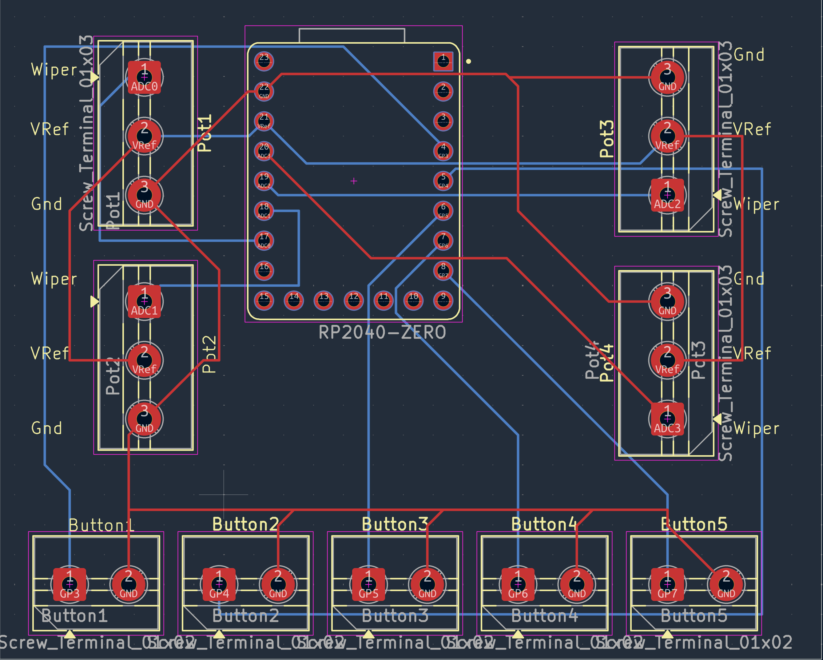
RP2040-Joystick is an open-source printed circuit board by DanTappan, from the DanTappan/Pico2Joystick repository on GitHub, published under the MIT licence. It is a 2-layer board of 68.6 × 55.9 mm with 10 parts on 23 nets, routed with 65 tracks and 0 vias.
It is built around the RP2040-ZERO. It belongs with the keyboards and input boards and the RP2040 boards of this library.
This is a simple USB Joystick written in CircuitPython, using the Joystick_XL library. Nothing particularly complex, most of the heavy lifting is done by Joystick_XL, but I'm making the repository public just in case anyone finds it useful
It should work with any microcontroller that support USB and CircuitPython. It uses CircuitPython rather than MicroPython because it requires support for USB HID.
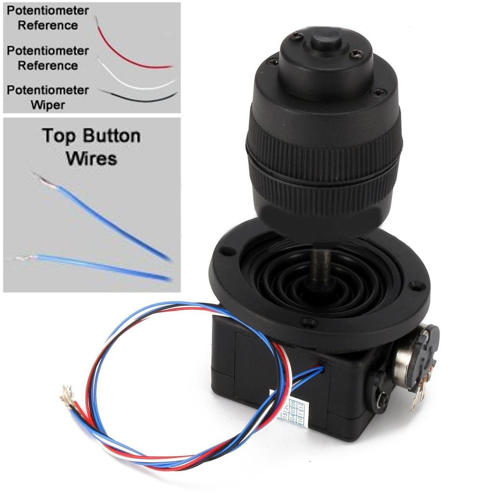
This uses the easily available Jh-D400X-R2 joystick (Aliexpress, Amazon,...)
config.py supports several different variants
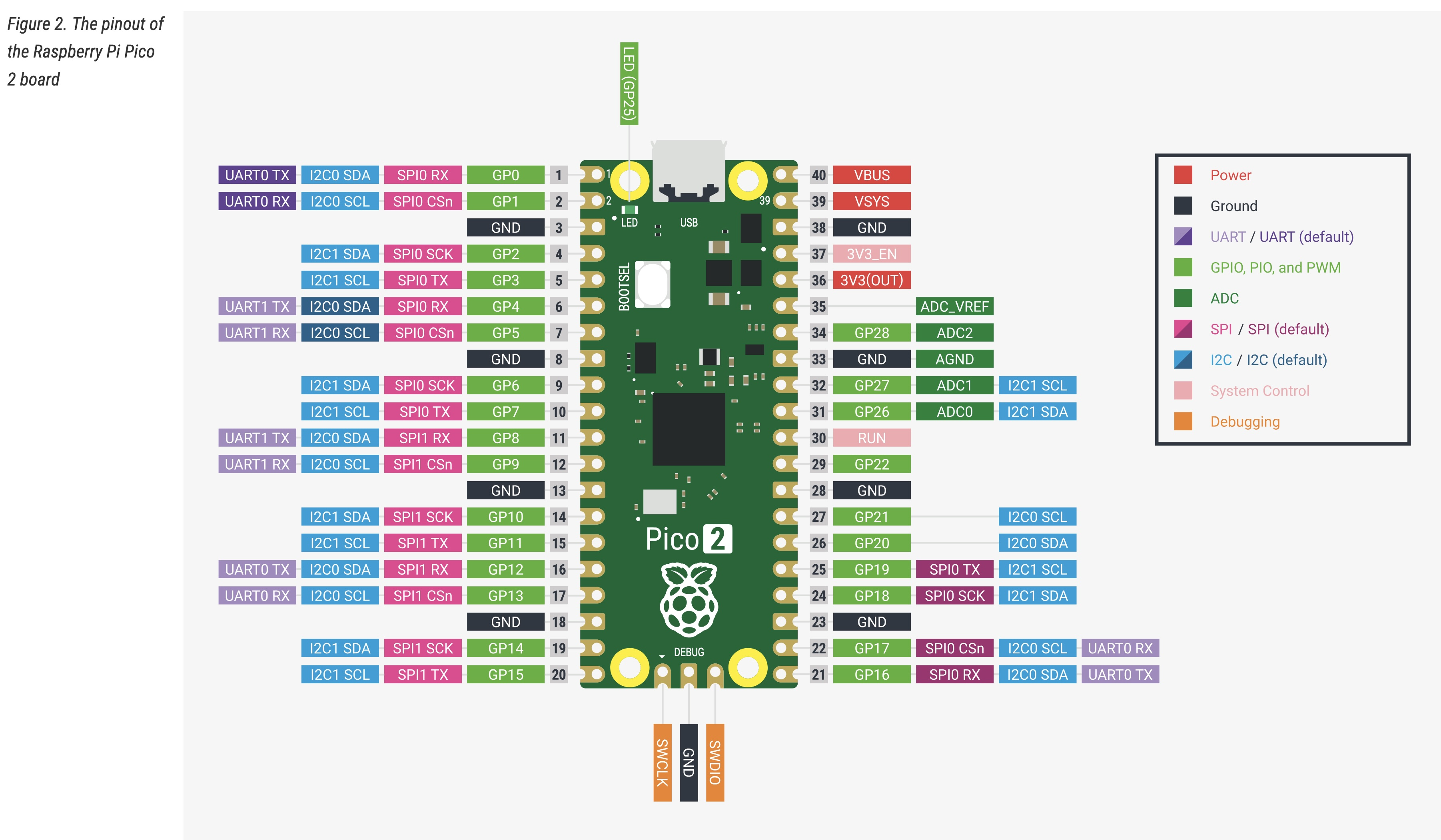
The original version of this was a simple 4 axis joystick with a single button, handwired to a Raspberry Pi Pico2, as follows:
| GP3 (pin 5) | joystick button (blue wire) |
| 3V3 (pin 36) | positive reference on joystick pots: red wire and left pot terminals |
| GND (pin 33) | other blue wire, black wire, and negative potentiometer reference (right pot terminals) |
| ADC2 (pin 34) | white wire |
| ADC1 (pin 32) | center terminal (wiper) on tilt pot |
| ADC0 (pin 31) | center terminal on pan pot |
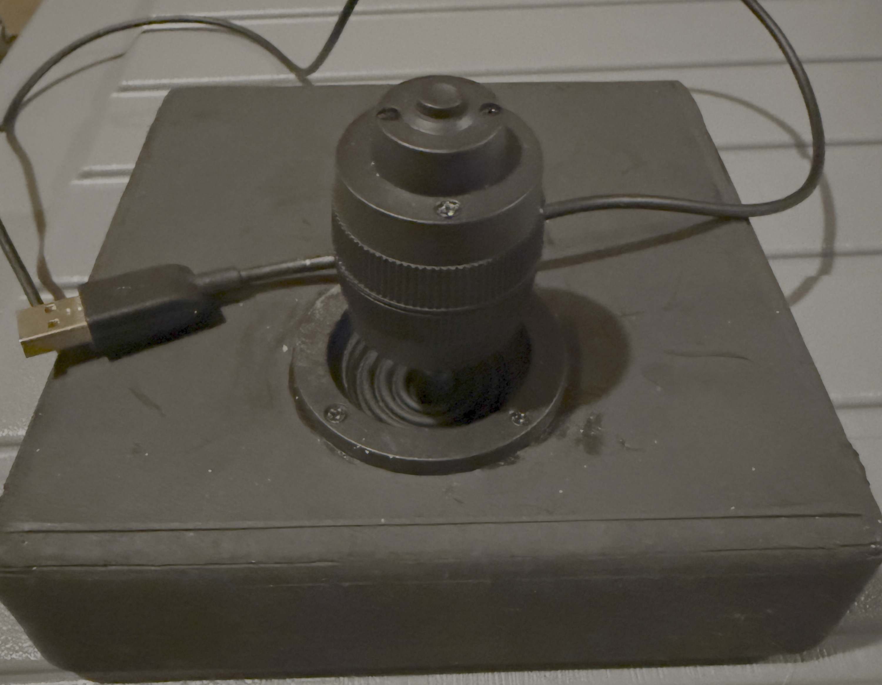
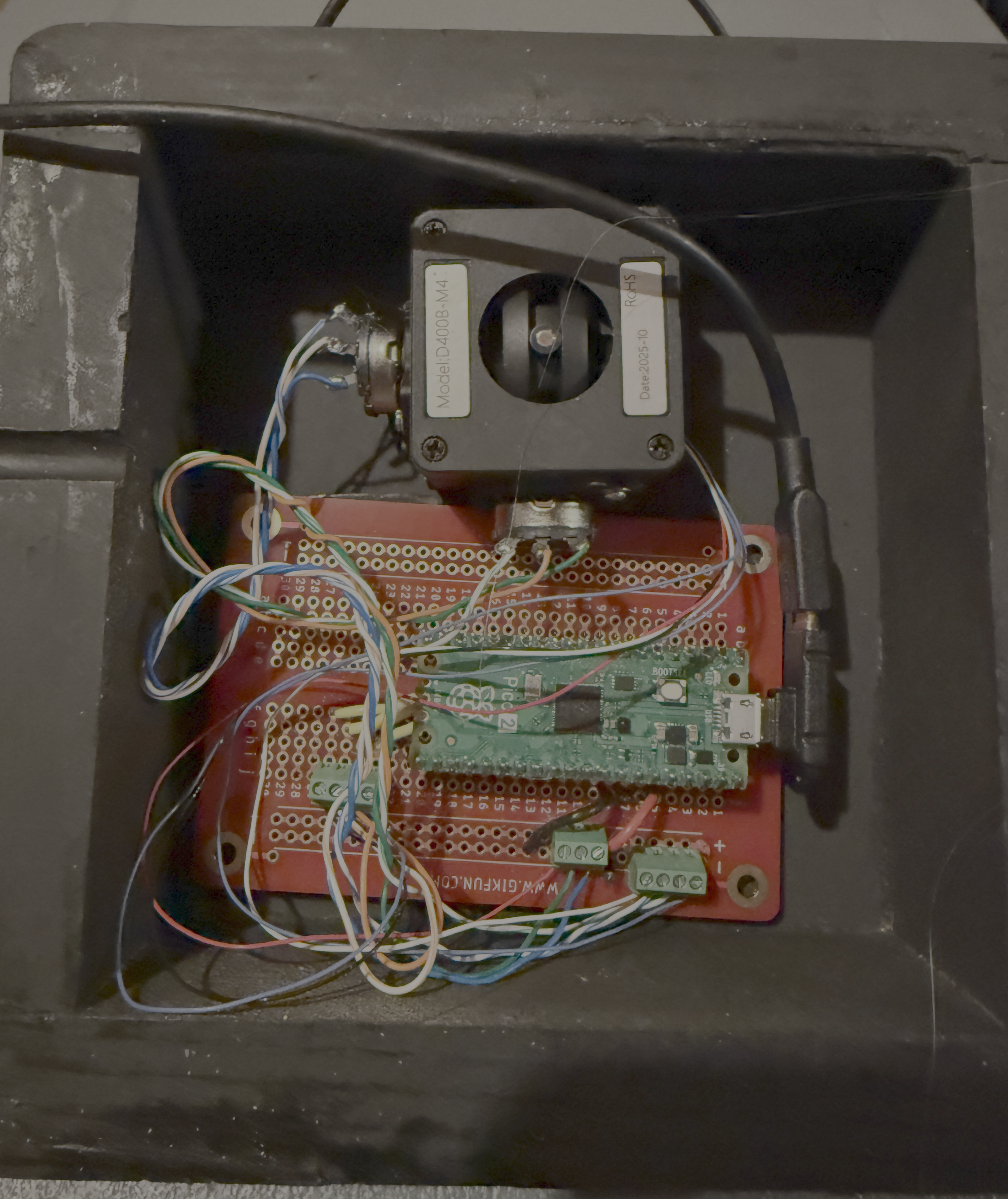
As a follow-on I've built a couple PCB based versions. The latest uses the Waveshare RP2040-Zero microcontroller, which has the advantage over the Pico2 of supporting 4 ADC channels.
The KiCad files for the PCB are in the KiCad folder. You will need to download the RP2040-ZERO symbols from SnapMagic
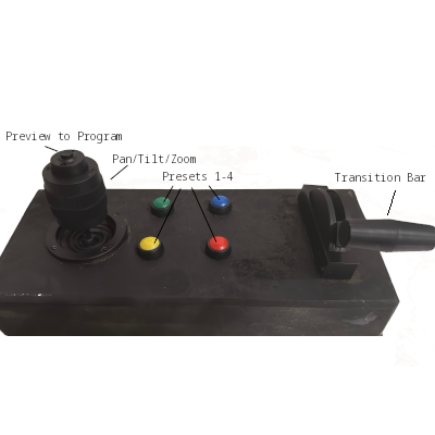
I use this with my VISCA Game Controller app for controlling Ethernet connected PTZ cameras.
Under normal use, the code does not export the CircuitPython filesystem to the connected computer. If you want to edit the code, you can cause it to export the filesystem by holding down the joystick button for 5 seconds after plugging in the USB connector. Alternatively, you can use (Thonny)[https://thonny.org/] and access the filesystem over the USB serial port.
| Qty | Value | Footprint | References |
|---|---|---|---|
| 5 | Screw_Terminal_01x02 | TerminalBlock:TerminalBlock_MaiXu_MX126-5.0-02P_1x02_P5.00mm | Button1, Button2, Button3, Button4, Button5 |
| 4 | Screw_Terminal_01x03 | TerminalBlock:TerminalBlock_MaiXu_MX126-5.0-03P_1x03_P5.00mm | Pot1, Pot2, Pot3, Pot4 |
| 1 | RP2040-ZERO | RP2040-ZERO:MODULE_RP2040-ZERO | U1 |
It measures 68.6 × 55.9 mm and has 2 copper layers, 1.6 mm thick.
10 parts, built around the RP2040-ZERO. The full list of its parts is on this page, with links to each part's symbol and footprint where PCBKit's library has them.
From the DanTappan/Pico2Joystick repository on GitHub, at the commit this page was made from: the board is KiCad/RP2040-Joystick.kicad_pcb and its schematic KiCad/RP2040-Joystick.kicad_sch. PCBKit opens the board in the browser, with nothing to install.
Its repository publishes it under the MIT licence: you may reuse it on that licence's terms (keep the author's notice, and for a copyleft licence share your changes alike).


beekeeb/zerosprey42
Zerosprey42 Keyboard is a wired, beginner friendly, choc hotswap, MonoBlockSplit (Unibody), column-staggered, DIY mechanical keyboard.


ravinrabbid/DonCon2040
RP2040 based firmware and hardware for DIY Taiko no Tatsujin Drum Controllers

nmur/RP2040-TestPatternGenerator
A simple test pattern generator running on the RP2040 microcontroller

ChrisChrisLoLo/bunchiez40
A pocket keyboard that makes use of mouse switches to achieve a miniscule size
