
2 layers128.1 × 87 mm
Virgil Controller
da-penguin-guy/Proteus
The Proteus is a modular collection of PCBs that will be used to develop the Virgil sound Protocol
78 parts3

The Proteus is a modular collection of PCBs that will be used to develop the Virgil sound Protocol
Panel is an open-source printed circuit board by da-penguin-guy, from the da-penguin-guy/Proteus repository on GitHub. It is a 2-layer board of 100.1 × 121.4 mm with 137 parts on 103 nets, routed with 1,618 tracks and 220 vias.
It is built around the RP2040, W25Q16JVSSIQ and CAP1293-1-SN-TR, with the DRV8220DSG, AFC07-S08ECC-00 and B103 among its other parts. Its parts include 38 capacitors, 18 ICs, 10 connectors, 4 resistors and 4 diodes. It belongs with the RP2040 boards of this library.


The Proteus is a modular collection of PCBs that will be used to develop the Virgil sound Protocol
Formerly known as the Virgil Controller, the Proteus is named after Proteus, a minor god from greek mythology. I chose this name because in Virgil's Georgics, he rapidly changes form, similar to how the Proteus is fully modular and can change quickly.
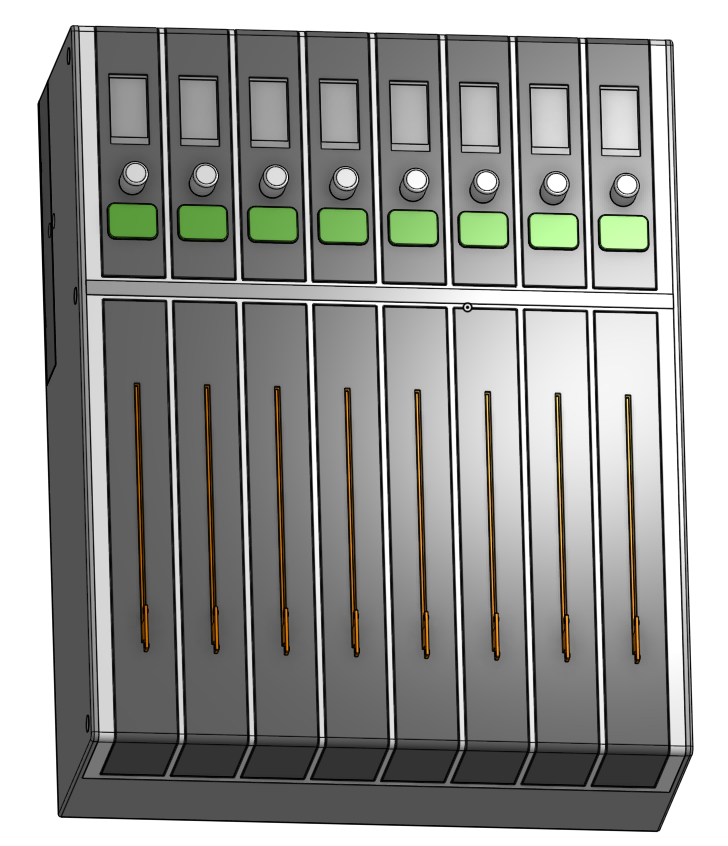
The Proteus doesn't fall into a good product class, primarily because this hasn't ever been done before. The best analog would be some midi controller, like the Behringer X-touch. However, this varies from that in several cases. Firstly, it will be fully open source, modular, and future proof. The other main difference is that it won't be using the MIDI protocol. I will be using this as a hardware prototype to develop the Virgil live sound protocol.
The Virgil protocol is a companion protocol to Audinate's Dante protocol, the industry standard for live audio transfer via a network. However, there is a significant gap in Dante: It only encompasses the audio transportation, not any additional communication. This is especially important for digital stageboxes, where the mixer needs control over physical hardware controls such as gain and phantom power. Because Dante doesn't allow for control packets, every popular audio company has created their own proprietary standard for transporting the information. This means that, despite Dante's goal of allowing for equipment from different companies to work together, productions are still limited to a single brand if they want a functional ecosystem.
The Virgil protocol solves this by being a universal language, allowing a variety of interconnectivity.
Cursor: Motor Speculum: Screen Ordo: Button
The controller itself has 16 module slots, 8 on the bottom and 8 on the top. Electrically, the slots are identical, but the slots have different lengths.
All modules (at this time) must have an rp2040/2350 microcontroller in them, and all communication over SPI.
Currently, the only module for the top slot is a display module that has a 1.14" TFT display, a button with a neopixel, and a continuous encoder with a neopixel. The display is the same as the Adafruit Newxie Tube, but just the panel can be found on AliExpress for significantly cheaper. For more information, go to the Proteus Speculum kicad project.
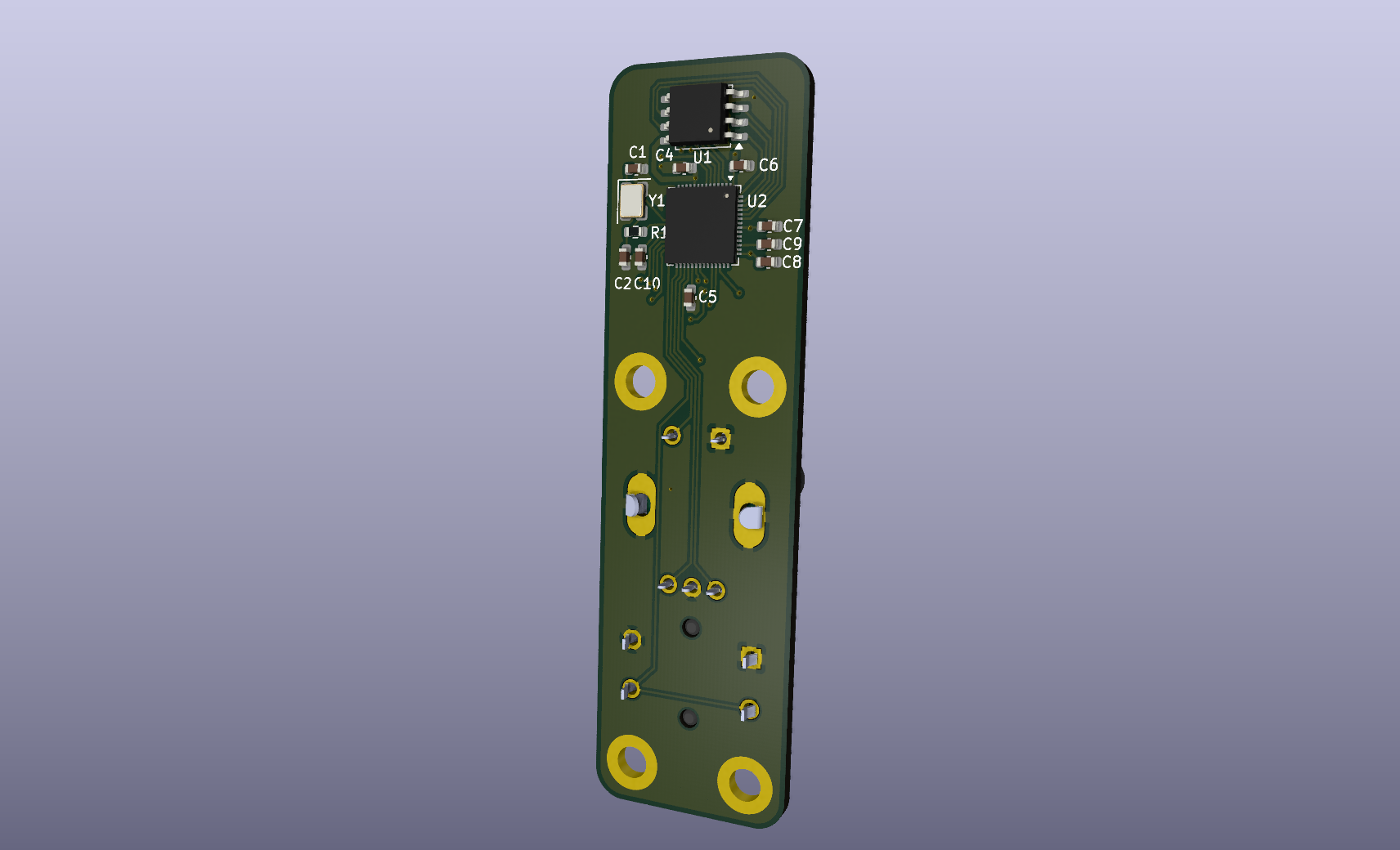
Currently, the only module for the bottom slot is a motorized fader using the B103 fader. These are the same faders used in the Behringer X-Touch, but they can be found for significantly cheaper on Alibaba. For more information, go to the Proteus Cursor kicad project.
The Proteus has 3 internal PCBs: The Motherboard, The Power Board, and The Backplane.
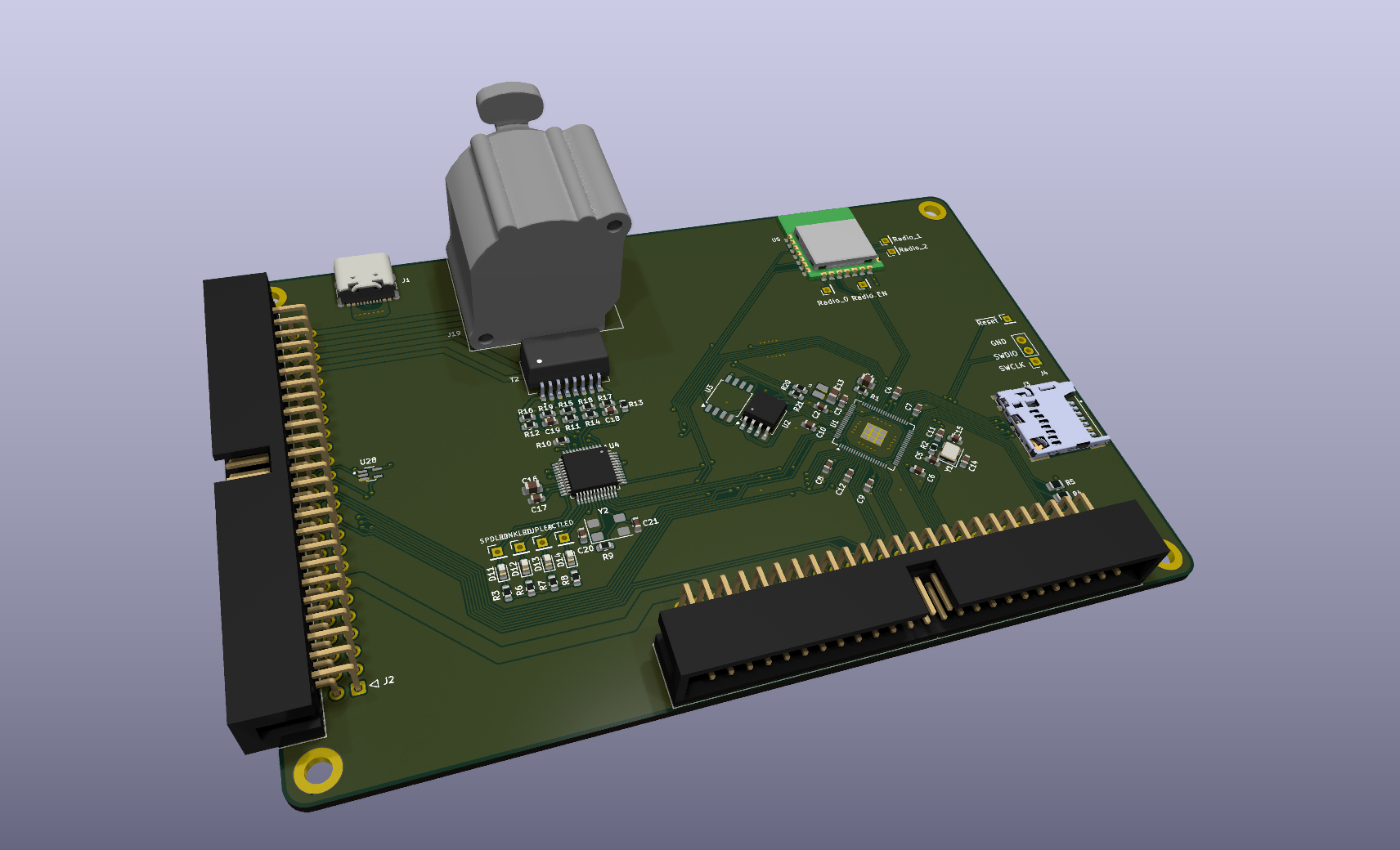
This is the actual brain of the device.
For external ports, it has an Ethercon port for networking and a USB-C port for programming.
For Internal ports, it has 2 50 pin IDC connectors, each with different pinouts. The first connects to the Power board and the second connects to the Backplane. The power board connects directly to the Controller, while the backplane connects via an IDC cable. There is also a microSD card connected via SDIO for icon storage.
For ICs the controller has an RP2350. It also has a W5500 for ethernet connectivity and the Raspberry Pi Radio Module 2 for wireless connectivity
The power module is designed to be completely separated and isolated from the main board. This is primarily because I want for this to eventually have a battery powered option, but I don't want to deal with a BMS yet.
The power module is expected to supply 3.3V, 5V, and a currently unknown motor VCC (somewhere between 9-12V). Motor VCC and current requirements will be determined after testing
Power modules are given a space on the back of the enclosure to expose their own power connectors. In addition, all the required signals for POE and USB-C PD are passed from the controller to the power board, including USB-C CC lines.
Currently, the only power module that has been developed supports POE and 12V in through a barrel jack. This power module is designed to be for very early prototyping. Because of that, the current module has an RP2350 on it, combined with current and voltage sensing on all lines. In addition, the motor VCC also has a smart power fuse and adjustable voltage via a DigiPot.
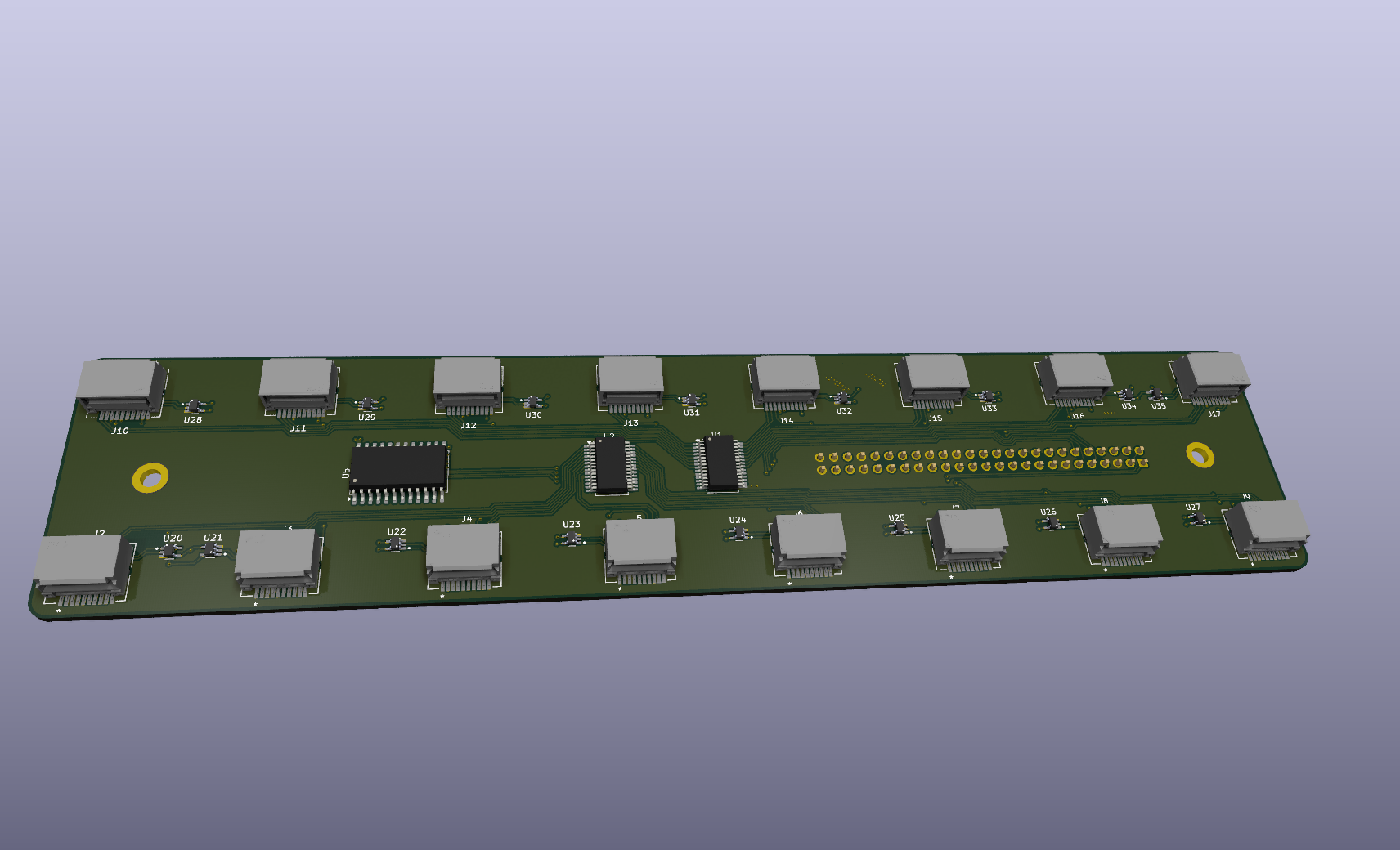
The backplane is the PCB that the modules plug into. This is kept separate so that extra module slots may be added in the future, and for simplifying enclosure design.
The main purpose of the backplane is to route connections from the 50 pin connector to the controller and each of the 16 modules. The signals that are being routed are various power lines, spi, SWD, and one singular GPIO. That gpio is tied directly to the controller, and was intended as an SPI interrupt. However, that will likely be removed in future iterations to allow for better scaling across more modules.
The backplane does have some ICs on it. The most notable is a CD74HC154M96, used to split the 4 CS mux lines from the controller to 16 CS lines for the modules. There are also 2 MCP23017T-E/SS I2C expanders, used for supplying reset lines to the modules and detect lines. The backplane also has 16 SN74CBTLV1G125DCKR, one for each module. This is used to switch the SWD lines on or off for each module, using the CS line as the control signal. This is so that the controller can program every module automatically.
| Qty | Value | Footprint | References |
|---|---|---|---|
| 30 | 100nF | Capacitor_SMD:C_0603_1608Metric | C10, C12, C14, C15, C16, C17, C18, C19, C20, C21, C22, C23, C25, C27, C28, C29 +14 |
| 24 | MountingHole_Pad | MountingHole:MountingHole_3.2mm_M3_DIN965_Pad | H1, H2, H10, H11, H12, H13, H14, H15, H16, H17, H18, H19, H20, H21, H22, H23 +8 |
| 8 | 15pF | Capacitor_SMD:C_0603_1608Metric | C1, C2, C11, C13, C24, C26, C33, C34 |
| 4 | 10056847-101LF | Snapeda:10056847-101LF-EDGE | J5, J6, J7, J8 |
| 4 | 1kΩ | Resistor_SMD:R_0603_1608Metric | R1, R2, R3, R4 |
| 4 | ABM8-272-T3 | Crystal:Crystal_SMD_Abracon_ABM8G-4Pin_3.2x2.5mm | Y1, Y2, Y3, Y4 |
| 4 | AFC07-S20FCC-00 | Snapeda:JUSHUO AFC07-S20FCC-00 | J1, J2, J3, J4 |
| 4 | RP2040 | Package_DFN_QFN:QFN-56-1EP_7x7mm_P0.4mm_EP3.2x3.2mm | U11, U12, U15, U16 |
| 4 | SK6812MINI | LED_SMD:LED_SK6812MINI_PLCC4_3.5x3.5mm_P1.75mm | D1, D2, D3, D4 |
| 4 | W25Q16JVSS | Package_SO:SOIC-8_5.3x5.3mm_P1.27mm | U7, U8, U17, U18 |
| 2 | AFC07-S08ECC-00 | Snapeda:Display Connector | U5, U6 |
| 2 | B103 | Snapeda:B103 | U3, U4 |
| 2 | B3F-4055 | Snapeda:SW_B3F-4055 | S3, S4 |
| 2 | CAP1293-1-SN-TR | Snapeda:SOIC8_4P9X3P9MC_MCH-L | U13, U14 |
| 2 | Conn_01x04_Pin | Connector_PinHeader_2.54mm:PinHeader_1x04_P2.54mm_Vertical | J9, J10 |
| 2 | DRV8220DSG | Package_SON:WSON-8-1EP_2x2mm_P0.5mm_EP0.9x1.6mm_ThermalVias | U9, U10 |
| 2 | PEC12R-4225F-S0024 | Snapeda:XDCR_PEC12R-4225F-S0024 | S1, S2 |
| 2 | SN74LVC1T45DBV | Package_TO_SOT_SMD:SOT-23-6 | U1, U2 |
| 2 | SS8550 | Package_TO_SOT_SMD:SOT-23 | Q1, Q2 |
The 108 most common of 137 parts.
da-penguin-guy/Proteus
The Proteus is a modular collection of PCBs that will be used to develop the Virgil sound Protocol

da-penguin-guy/Proteus
The Proteus is a modular collection of PCBs that will be used to develop the Virgil sound Protocol

da-penguin-guy/Proteus
The Proteus is a modular collection of PCBs that will be used to develop the Virgil sound Protocol

da-penguin-guy/Proteus
The Proteus is a modular collection of PCBs that will be used to develop the Virgil sound Protocol

da-penguin-guy/Proteus
The Proteus is a modular collection of PCBs that will be used to develop the Virgil sound Protocol

da-penguin-guy/Proteus
The Proteus is a modular collection of PCBs that will be used to develop the Virgil sound Protocol

da-penguin-guy/Proteus
The Proteus is a modular collection of PCBs that will be used to develop the Virgil sound Protocol


zaxour/TurboNanza
An internal RGB, S-Video, Composite video and Audio modification for the Turbografx 16

tangles-0/cyberdeck-scout
// #ifndef PINPA0 // #define PINPA0 11 // #endif // #ifndef PINPA1 // #define PINPA1 8 // #endif // #ifndef PINPA2 // #define PINPA2 9 // #endif // #ifndef PINPA3 // #define PINPA3 10 // #endif // #ifndef PINPA4 //…


It measures 100.1 × 121.4 mm and has 2 copper layers, 1.6 mm thick.
137 parts, built around the RP2040, W25Q16JVSSIQ, CAP1293-1-SN-TR and DRV8220DSG. The full list of its parts is on this page, with links to each part's symbol and footprint where PCBKit's library has them.
From the da-penguin-guy/Proteus repository on GitHub, at the commit this page was made from: the board is PCB/Panel/Panel.kicad_pcb and its schematic PCB/Proteus Backplane/BoardConnector.kicad_sch. PCBKit opens the board in the browser, with nothing to install.
Its repository states no licence, so its author keeps all rights: ask da-penguin-guy before reusing the design.