4 layers116 × 55 mm

 hansgaensbauer/MR-Core2
Open Source Magnetic Resonance Imaging Console
MR Core is an open-source printed circuit board by hansgaensbauer, from the hansgaensbauer/MR-Core repository on GitHub, published under the CERN-OHL-W-2.0 licence. It is a 4-layer board of 96.5 × 116 mm with 360 parts on 475 nets, routed with 5,171 tracks and 745 vias.
It is built around the LAN8742A-CZ, DRV8220DSG and DAC5687IPZP, with the FT601Q-B-T, IS25LP256D-RMLE-TR and LD29300P2M among its other parts. Its parts include 199 capacitors, 77 resistors, 20 connectors, 16 ICs and 6 diodes.


An FPGA Driven DAC + ADC for Magnetic Resonance, intended as a capable controller for Magnetic Resonance Imaging and Magnetic Resonance Relaxometry.
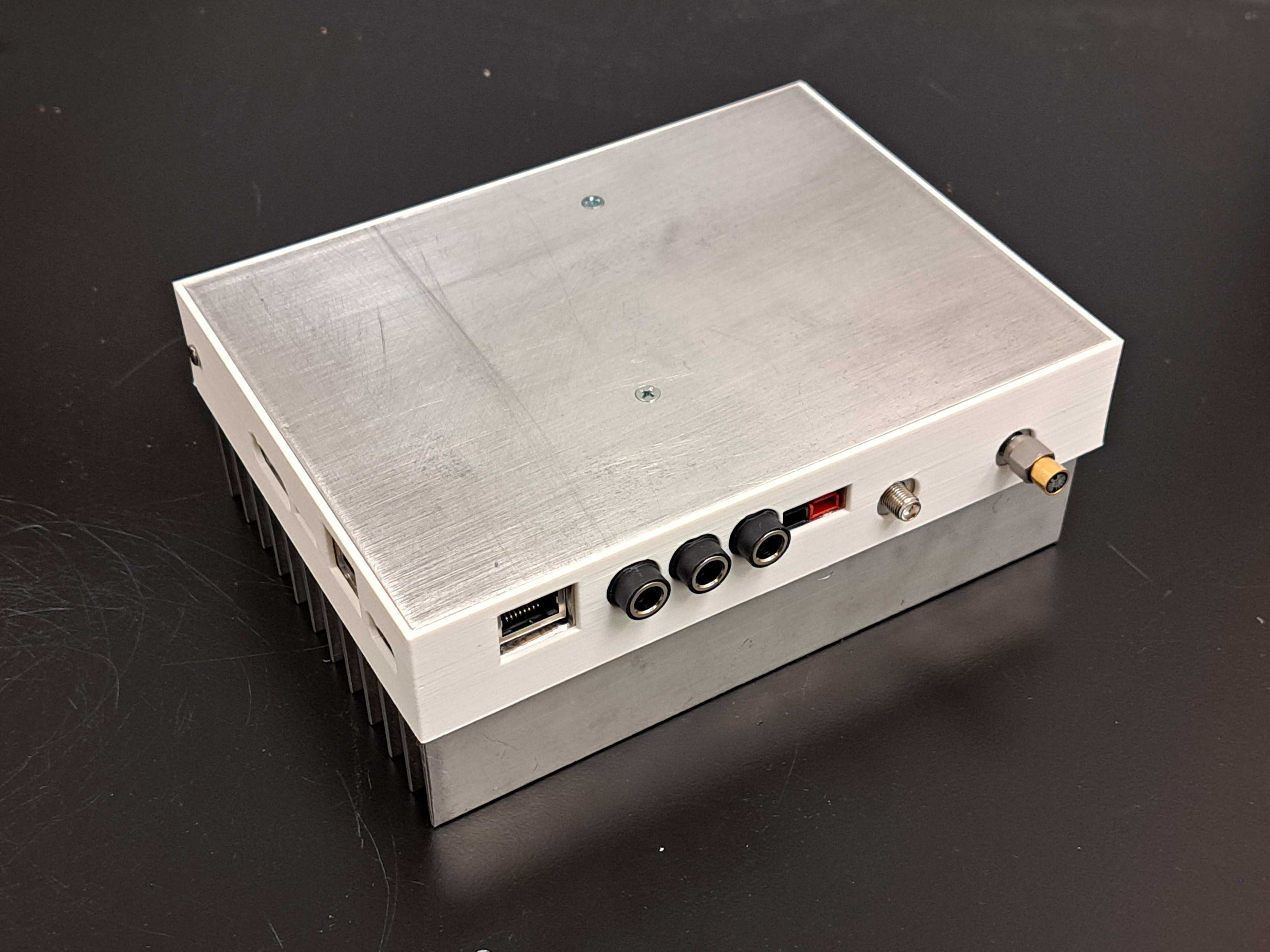
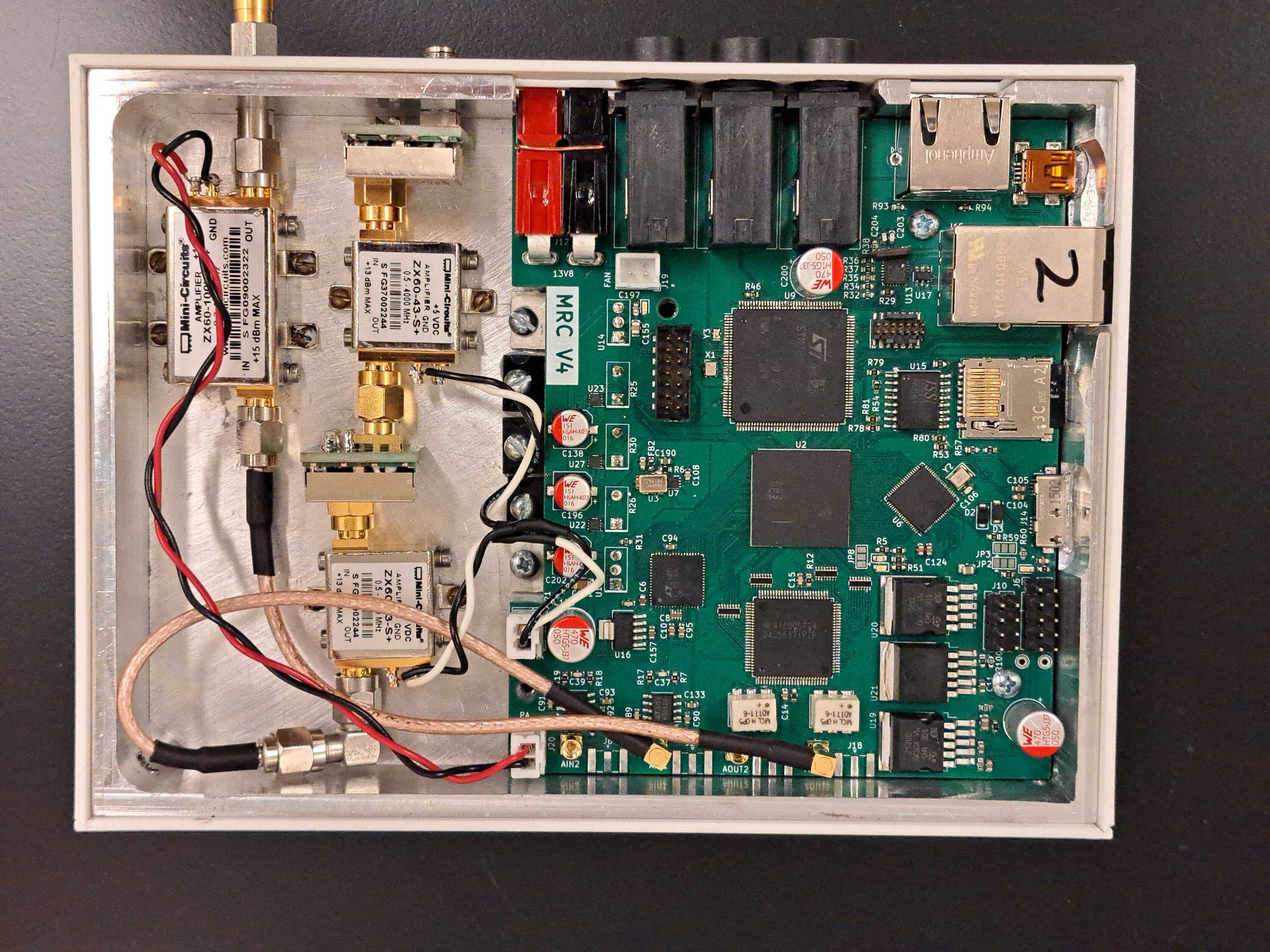
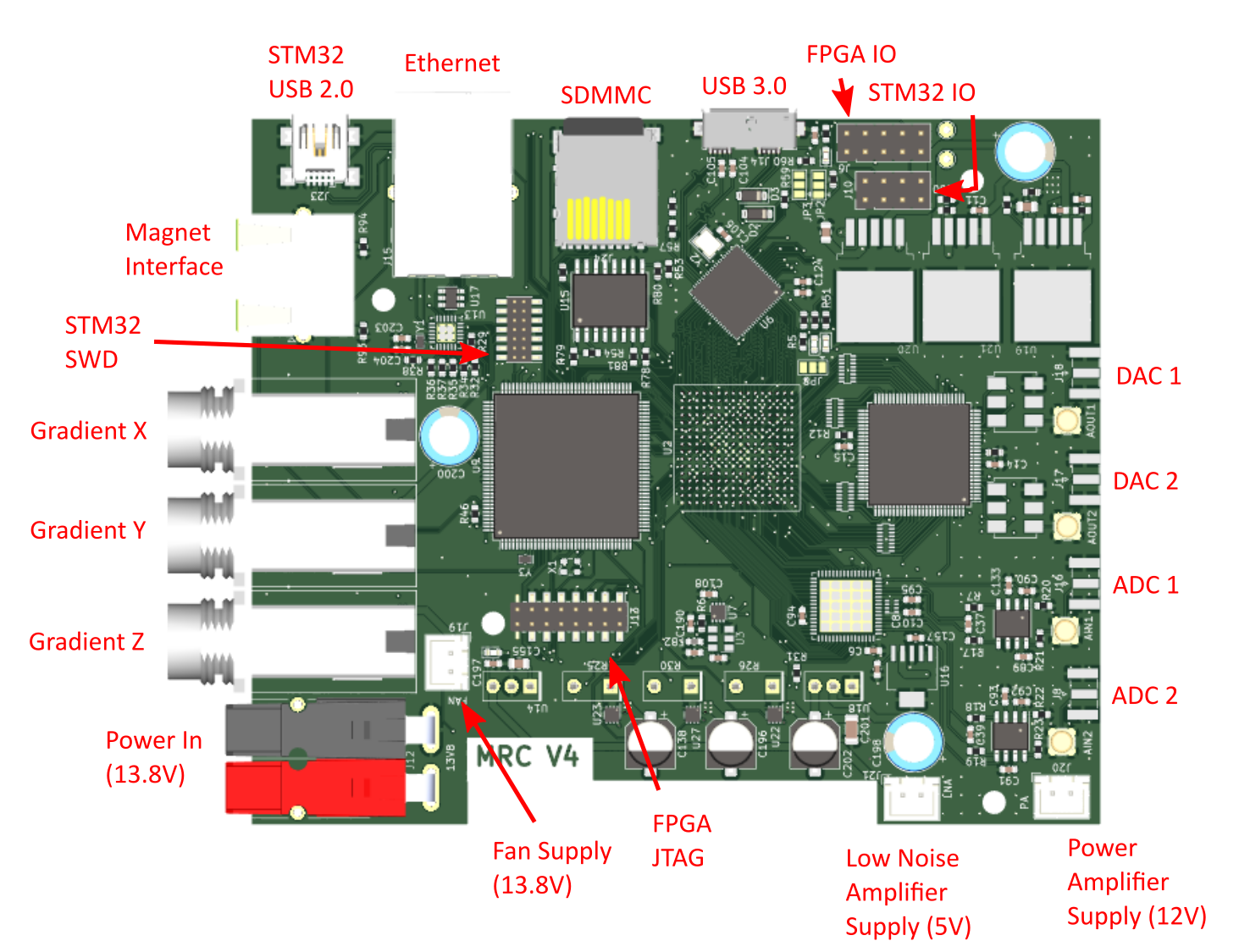
The MR-Core is designed to work with a 13.8V DC power supply, such as those sold by Astron Corporation. These are commonly used for amateur radio, but any linear power supply capable of providing 10A continuously is suitable. If the gradients are not used, only 3A are required. The power connector is a ASMPR45-1X2-RK from Anderson Power Products, Inc..
By default, new designs programmed into the FPGA must be reprogrammed every time the device loses power. To allow the FPGA image to persist between reboots, a SPI configuration flash is included that can program the FPGA with a default image on startup. To change this default image:
To program the SPI flash without changing the configuration (which you will want to do in most cases to update the FPGA image), the steps are more simple.
The AFE for the MRC consists of two SXLP-21.4+ lowpass filters and two ZX60-43-S+ gain block amplifiers for the receive side, and one ZX60-100VHX+ amplifier for transmit. The amplifiers are powered by connectors from the MRC PCB, and should not be used with the heatsink removed. The transmit amplifier may be destroyed if it transmits into a poorly tuned or disconnected probe. For development, the transmit port of the MRC should be connected to a 50 ohm termination. The filters can be bypassed by soldering an 0603 resistor onto the jumpers on the filter PCBs. The MRC AFE is intended to be used with an external switch and preamplifier located on the probe - the gain blocks are not low noise amplifiers.
The magnet interface is connected to the MRC using an ethernet cable. The interface exposes FPGA IO for switching, as well as 3.3V power and microcontroller IO for general use.
The gradients use 1/4" TRS audio connectors. Do not use 1/4" mono connectors, and do not insert or remove the connectors for the gradients when the board is powered. Doing so can damage the gradient drivers. The gradients are driven by H-bridge circuits to the supply voltage, current limited to 3A by three power resistors on the board. For this reason, neither contact for the gradients (Tip or Ring) is grounded. The Shield should not be connected to the gradient coil.
Support for direct baseband sample streaming with Steam-O-Scope firmware from Joseph Feld.
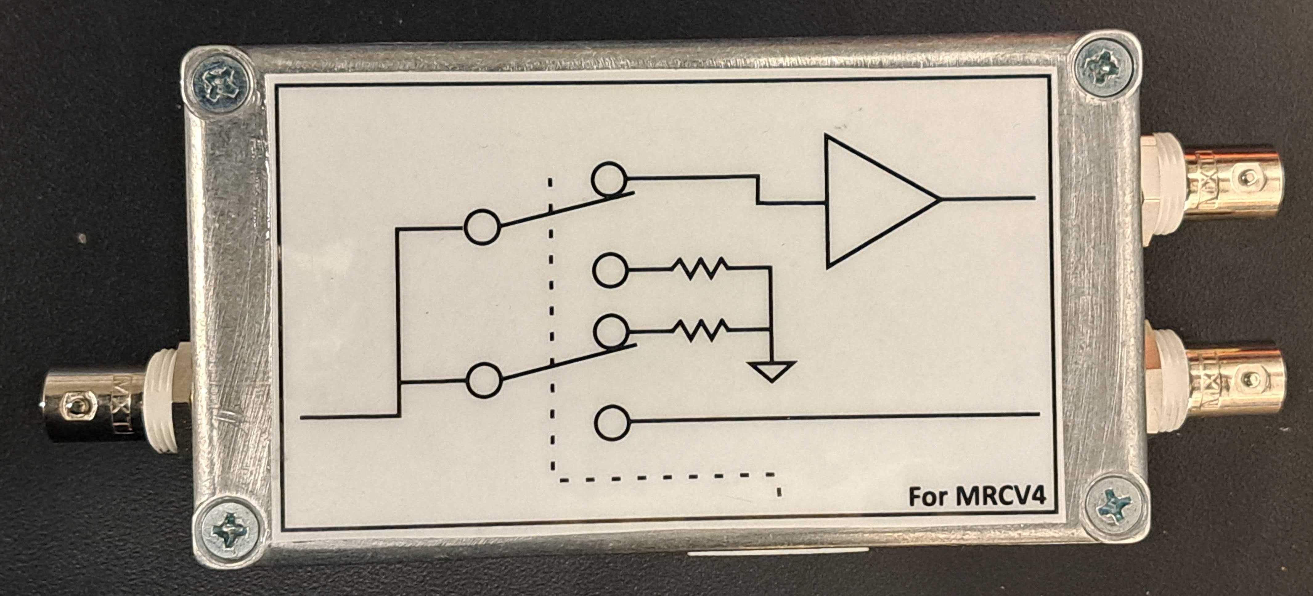
In order to make it possible to use non-MRC compatible probes with the MRC, a switch and preamplifier module is provided. This module provides about 10dB of gain and it includes a ZX80-DR230-S+ absorbtive RF switch. The truth table for the switch is:
| SW[1] | SW[0] | Switch State |
|---|---|---|
| 0 | 0 | Both Off |
| 0 | 1 | Receive |
| 1 | 0 | Transmit |
| 1 | 1 | Unknown |
The yellow LED on the preamplifier module ethernet connector indicates the status of the transmit switch (on = closed) and the green LED likewise indicates the status of the receive switch.
This image implements a general purpose, programmable controller for MRI sequences.
The system is programmed by the STM32 over SPI, and each SPI transaction is 16 bits with the MSB first. There are three types of SPI command: control register programming, frequency tuning word programming, and sequence programming.
The control register is used for general purpose control of the FPGA, and can be accessed with a SPI transaction where bits [15:14] are 0b10. The 8 LSBs give the new control register value. The control register is shown below:
CMD (Opcode 0b00)
[  7  |  6  |  5  |  4  |  3  |  2  |  1  |  0  ]
[ RST |     |     |     |     |     |TRIG |     ]
To program the 16 bit frequency tuning word, the system must first be put into frequency tuning mode by sending the frequency tuning command 0xC000. The frequency tuning word is sent on the next transaction, and the system will automatically return to IDLE afterward.
To enter sequence programming, the sequence programming command must be sent with the number of lines in the sequence program. The programming command starts with 0b00, and the 14 LSBs are the number of 16 bit instructions in the sequence.
The MRC uses a very simple instruction set designed for precise execution of any pulse sequences. There are four instructions:
CMD (Opcode 0b00)
[ 15 | 14 | 13 | 12 | 11 | 10 |  9 |  8 |  7 |  6 |  5 |  4 |  3 |  2 |  1 |  0 ]
[  0 |  0 |   AMP   |  PHASE  |   GRX   |   GRY   |   GRZ   |      RESERVED     ]
Change the transmitter amplitude and phase to the values indexed by AMP and PHASE. Set the gradients to the values set by GR[xyz].
LSET (Opcode 0b01)
[ 15 | 14 | 13 | 12 | 11 | 10 |  9 |  8 |  7 |  6 |  5 |  4 |  3 |  2 |  1 |  0 ]
[  0 |  1 | COUNTER |                          VALUE                            ]
Set COUNTER to VALUE.
JMP (Opcode 0b10)
[ 15 | 14 | 13 | 12 | 11 | 10 |  9 |  8 |  7 |  6 |  5 |  4 |  3 |  2 |  1 |  0 ]
[  1 |  0 | COUNTER |                         ADDRESS                           ]
If COUNTER is not zero, jump to the absolute ADDRESS. If COUNTER is zero, set COUNTER to 0xFFFF and advance the instruction counter.
HALT (Opcode 0b11)
[ 15 | 14 | 13 | 12 | 11 | 10 |  9 |  8 |  7 |  6 |  5 |  4 |  3 |  2 |  1 |  0 ]
[  1 |  1 |                                                                     ]
Terminates the sequence.
To better compress the immediates for programming amplitude and phase so that all of the pulse parameters can be updated simultaneously, the AMP and PHASE fields in the CMD instruction do not directly specify the amplitude or phase, but instead give the address of the correct value within separate lookup tables that are programmed with the sequence. The first four lines of the sequence program are the four amplitude fields, and the second four lines are the four phase fields.
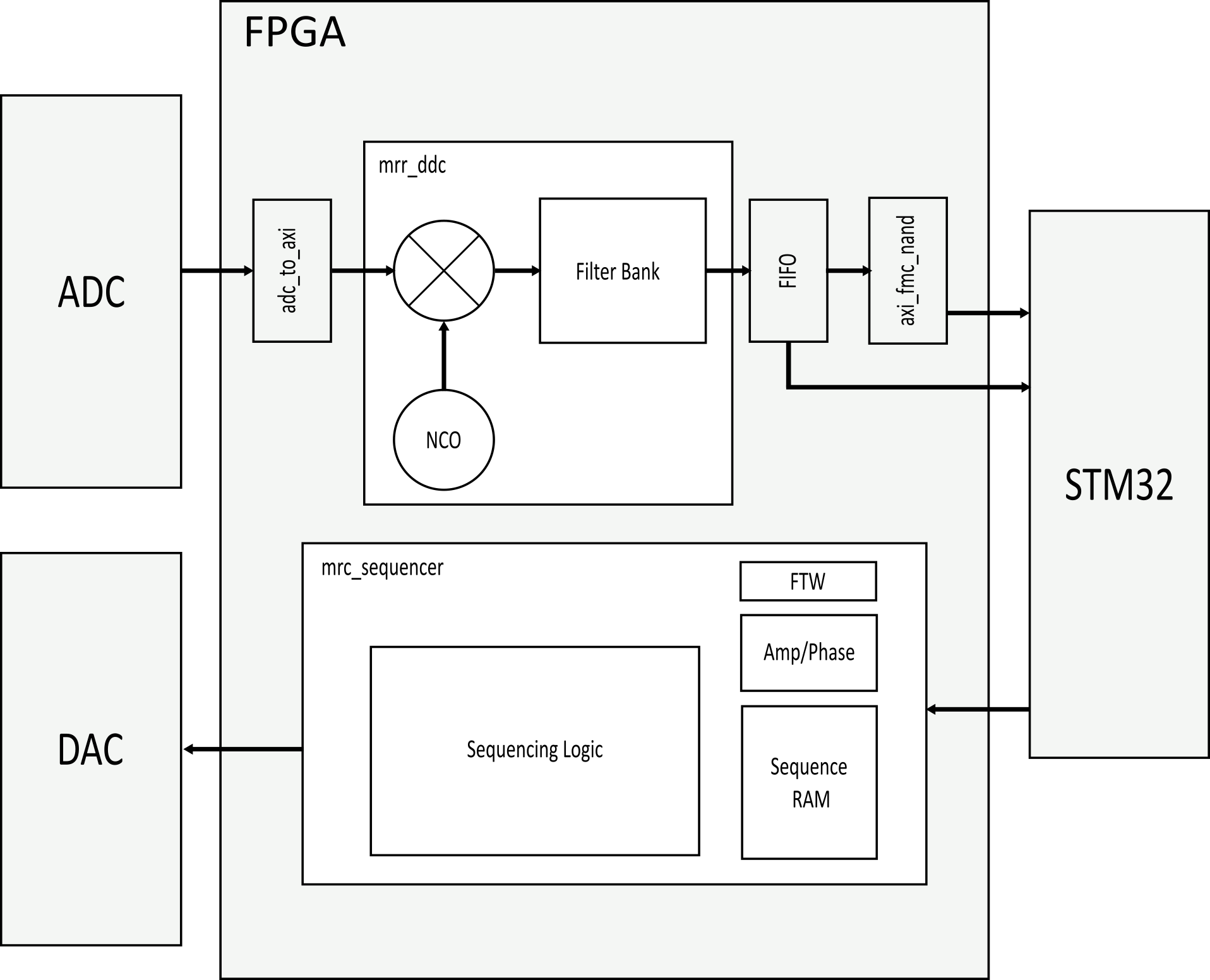
The 120MSps data stream from the ADC is too much data for the STM32 to process, and most of this data is useless as it covers frequencies far away from the Larmor frequency of the magnet. To lower the data rate and isolate only a certain band of interest, the FPGA can digitally downconvert and downsample the ADC data stream. The digital design responsible for this is contained in the "mrr-ddc" block design within the MR-Core Vivado project.
The structure of the DDC is shown in the HDL block diagram above. The parallel data is converted to AXI by the adc_to_axi module. This is fed into the mrr-ddc block design, which includes a complex multiplier and direct digital synthesizer for downconversion. The frequency shifted products are filtered and passed to a FIFO, before being passed to the STM32 using the STM32 Flexible Memory Controller (FMC).
The layout of the digital filter is shown below:
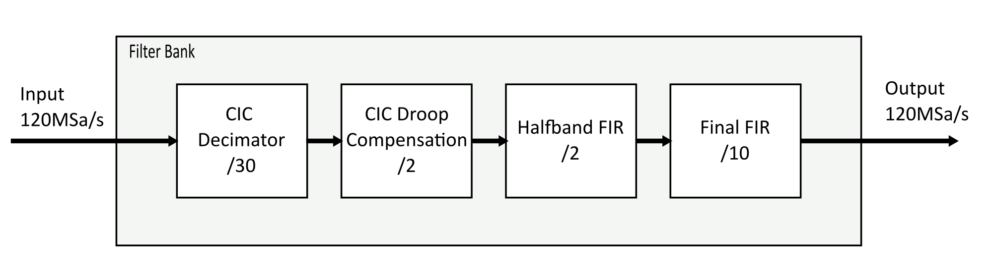
This filter is responsible for both decimation and the bulk of noise rejection, so the performance requirements are strict. The filter is implemented in several stages so that the high complexity FIR filters at the end see only data streams that are already significantly decimated (the final FIR filter sees an input data rate of 1MSa/s, compared to 120MSa/s for the CIC decimator).
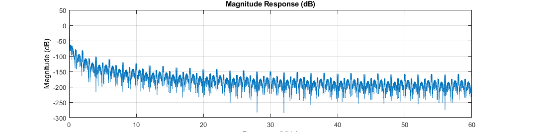
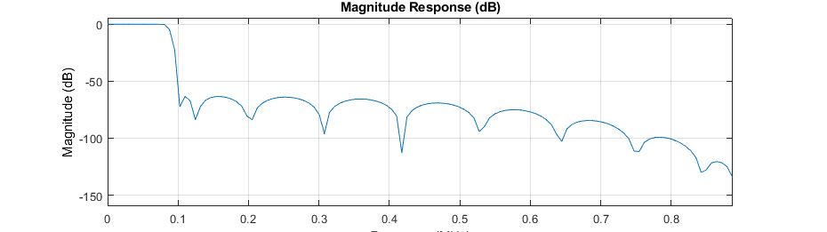
The filter design is done in Matlab, and the current design is captured by filtdesign.m in MR-Core->hdl->Utilities. The transfer function is shown below (x axes in MHz):
The firmware running on the STM32 is responsible for processing or passing the data stream from the FPGA during receive, and also for configuring the FPGA, the DAC, and the ADC. The mrc STM32CubeIDE project in the "firmware" folder provides C drivers for the DAC, the ADC, and an "MRC" driver that handles communication with the FPGA, pulse sequencing, and data streaming. The DAC and ADC drivers provide access to the test patterns, power down states, and programming registers for these chips.
For USB 2.0 Full speed data streaming, the Transfer_Buffer() function in mrc.c will coordinate FMC reads into a ping-pong buffer that is then emptied over the USB CDC hardware into a PC. A basic serial command interface is available in this demo so that a user can trigger pulse-echo sequences by sending the command pulseecho over USB CDC.
A limited Pulseq compiler is provided in software. This program requires pypulseq to run, however, the latest stable release of pypulseq cannot run with the most recent versions of numpy. This can be solved by replacing every instance of np.float and np.complex in the sigpy and pypulseq libraries with float and complex respectively.
To run the compiler, use py mrc_pulseq_assembler.py [sequence_file.seq] where [sequence_file.seq] is replaced by the path to your pulseq file. This will generate a .mrc file with the machine code for the MRI. To facilitate debugging, a objdump-style disassembler is also provided. To run the disassembler, use py mrcdump.py [mrc_file.mrc] where [mrc_file.mrc] is replaced with the path to your .mrc file. It will produce an output in the following format:
Statics:
Phase 0: 0
Phase 1: 0
Phase 2: 0
Phase 3: 0

Amp 0: 0
Amp 1: 28000
Amp 2: 56000
Amp 3: 0

Instructions:
0:      0001000000000000        cmd     1 0 00 00 00
1:      0100010010101111        lset    0 1199
...     ...                     ...     ...
20:     0000000000000000        cmd     0 0 00 00 00
21:     1100000000000000        halt.
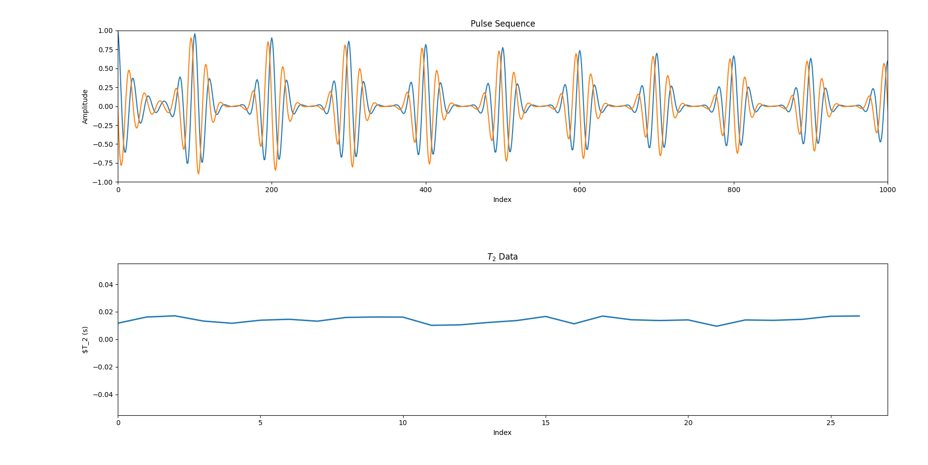
For the system demo, a python driver for the MRC board is available in the "software" folder. bioreactormonitoring.py uses this driver to periodically acquire pulsecho sequences and plot the received data and extracted T2 values on an animated graph on the computer.
Best practices: make your own branch!
| Qty | Value | Footprint | References |
|---|---|---|---|
| 62 | 100n | Capacitor_SMD:C_0603_1608Metric | C10, C102, C103, C104, C105, C109, C111, C113, C115, C118, C120, C122, C124, C126, C128, C130 +46 |
| 27 | 470n | Capacitor_SMD:C_0603_1608Metric | C18, C110, C112, C114, C116, C125, C127, C129, C131, C150, C175, C176, C177, C181, C182, C183 +11 |
| 17 | 1u | Capacitor_SMD:C_0603_1608Metric | C68, C69, C70, C76, C77, C90, C92, C96, C108, C123, C147, C153, C164, C166, C191, C208 +1 |
| 16 | 4.7u | Capacitor_SMD:C_0603_1608Metric | C11, C21, C22, C32, C33, C36, C40, C41, C132, C159, C172, C173, C178, C179, C186, C187 |
| 14 | 10k | Resistor_SMD:R_0603_1608Metric | R3, R4, R13, R24, R31, R32, R33, R35, R38, R39, R46, R48, R57, R101 |
| 14 | 10n | Capacitor_SMD:C_0603_1608Metric | C2, C3, C7, C9, C15, C61, C73, C74, C75, C78, C82, C89, C91, C158 |
| 13 | 10u | Capacitor_SMD:C_0603_1608Metric | C28, C29, C45, C48, C65, C66, C67, C71, C72, C85, C157, C161, C190 |
| 12 | FerriteBead_Small | Inductor_SMD:L_0603_1608Metric | FB1, FB2, FB3, FB4, FB5, FB6, FB7, FB8, FB9, FB10, FB11, FB15 |
| 11 | 4.7k | Resistor_SMD:R_0603_1608Metric | R2, R5, R51, R53, R54, R56, R76, R81, R93, R94, R99 |
| 8 | 100 | Resistor_SMD:R_0603_1608Metric | R16, R28, R58, R59, R77, R78, R79, R80 |
| 8 | 51 | Resistor_SMD:R_0603_1608Metric | R10, R11, R14, R15, R40, R41, R42, R43 |
| 6 | 47u | Capacitor_SMD:C_0603_1608Metric | C79, C80, C81, C83, C84, C174 |
| 6 | DRV8220 | Package_SON:WSON-8-1EP_2x2mm_P0.5mm_EP0.9x1.6mm | U10, U22, U23, U24, U27, U28 |
| 5 | 100u | Capacitor_SMD:C_0603_1608Metric | C25, C34, C42, C180, C188 |
| 4 | 10u | Capacitor_SMD:C_0805_2012Metric | C135, C136, C199, C206 |
| 4 | 18p | Capacitor_SMD:C_0603_1608Metric | C37, C39, C106, C107 |
| 4 | 1k | Resistor_SMD:R_0603_1608Metric | R6, R27, R97, RBIAS1 |
| 4 | 33 | Resistor_SMD:R_0603_1608Metric | R29, R34, R36, R37 |
| 4 | 330n | Capacitor_SMD:C_0603_1608Metric | C5, C134, C154, C197 |
| 4 | 402 | Resistor_SMD:R_0603_1608Metric | R20, R21, R22, R23 |
| 4 | 49.9 | Resistor_SMD:R_0603_1608Metric | R7, R17, R18, R19 |
| 4 | Conn_Coaxial | Connector_Coaxial:SMA_Samtec_SMA-J-P-X-ST-EM1_EdgeMount | J8, J16, J17, J18 |
| 4 | Conn_Coaxial | Connector_Coaxial:MMCX_Molex_73415-1471_Vertical | J1, J2, J3, J4 |
| 4 | EXB-2HV470JV | BioMEMS:CAY16-470J8LF | RN3, RN4, RN5, RN6 |
| 3 | 10p | Capacitor_SMD:C_0603_1608Metric | C12, C148, C149 |
| 3 | 150u | Capacitor_SMD:CP_Elec_6.3x5.8 | C138, C196, C202 |
| 3 | 2.2u | Capacitor_SMD:C_0603_1608Metric | C6, C100, C101 |
| 3 | 3.3k | Resistor_SMD:R_0603_1608Metric | R60, R96, R100 |
| 3 | 47u | Capacitor_THT:CP_Radial_D8.0mm_P3.50mm | C139, C198, C200 |
| 3 | 6.8n | Capacitor_SMD:C_0603_1608Metric | C117, C119, C121 |
| 3 | Conn_01x02 | Connector_JST:JST_XH_B2B-XH-A_1x02_P2.50mm_Vertical | J19, J20, J21 |
| 3 | Heater | BioMEMS:TO-220-2_BottomHeatsink | R25, R26, R30 |
| 3 | LED_Small | LED_SMD:LED_0603_1608Metric | D7, D8, D9 |
| 3 | SJ-63063B | BioMEMS:SJ-63063B | J5, J7, J22 |
| 2 | 1u | Capacitor_SMD:C_0805_2012Metric | C137, C155 |
| 2 | 220n | Capacitor_SMD:C_0603_1608Metric | C170, C171 |
| 2 | 270 | Resistor_SMD:R_0603_1608Metric | R45, R87 |
| 2 | 30p | Capacitor_SMD:C_0603_1608Metric | C203, C204 |
| 2 | ADTT1-6 | RF_Mini-Circuits:Mini-Circuits_CD637_H5.23mm | TR1, TR2 |
| 2 | D_TVS_Filled | Diode_SMD:D_SOD-123 | D2, D3 |
| 2 | Jumper_3_Open | Jumper:SolderJumper-3_P1.3mm_Open_Pad1.0x1.5mm | JP2, JP3 |
| 2 | LD29300 | BioMEMS:P2PAK | U19, U20 |
| 2 | LT6600-xx | Package_SO:SO-8_3.9x4.9mm_P1.27mm | U4, U8 |
| 2 | SolderJumper_3_Bridged12 | Jumper:SolderJumper-3_P1.3mm_Bridged2Bar12_Pad1.0x1.5mm | JP4, JP8 |
| 2 | TestPoint | TestPoint:TestPoint_THTPad_D2.0mm_Drill1.0mm | TP7, TP8 |
| 1 | XLH736120.000000I | BioMEMS:XLH736120.000000I | U3 |
| 1 | 1.6k | Resistor_SMD:R_0603_1608Metric | R64 |
| 1 | 10 | Resistor_SMD:R_0603_1608Metric | R8 |
| 1 | 10u | Capacitor_SMD:C_1206_3216Metric | C201 |
| 1 | 12.1k | Resistor_SMD:R_0603_1608Metric | R89 |
| 1 | 2.2k | Resistor_SMD:R_0603_1608Metric | R98 |
| 1 | 2.2u | BioMEMS:0508_C_INTERDIGITATED | C8 |
| 1 | 20k | Resistor_SMD:R_0603_1608Metric | R102 |
| 1 | 22 | Resistor_SMD:R_0603_1608Metric | R12 |
| 1 | 30Meg | Crystal:Crystal_SMD_3225-4Pin_3.2x2.5mm | Y2 |
| 1 | 32.768k | Crystal:Crystal_SMD_MicroCrystal_CM9V-T1A-2Pin_1.6x1.0mm | Y3 |
| 1 | 330 | Resistor_SMD:R_0603_1608Metric | R47 |
| 1 | 330p | Capacitor_SMD:C_0603_1608Metric | C17 |
| 1 | 33n | Capacitor_SMD:C_0603_1608Metric | C16 |
| 1 | 33u | Capacitor_SMD:C_0603_1608Metric | C160 |
| 1 | 47 | Resistor_SMD:R_0603_1608Metric | R44 |
| 1 | 470 | Resistor_SMD:R_0603_1608Metric | R52 |
| 1 | 470p | Capacitor_SMD:C_0603_1608Metric | C207 |
| 1 | 5.62k | Resistor_SMD:R_0603_1608Metric | R95 |
| 1 | 50M | Oscillator:Oscillator_SMD_ECS_2520MV-xxx-xx-4Pin_2.5x2.0mm | X1 |
| 1 | 6.2k | Resistor_SMD:R_0603_1608Metric | R1 |
| 1 | 93.1 | Resistor_SMD:R_0603_1608Metric | R9 |
| 1 | ASMPR45-1X2-RK | BioMEMS:Powerpole_1x2 | J12 |
| 1 | Conn_02x04_Odd_Even | Connector_PinHeader_2.54mm:PinHeader_2x04_P2.54mm_Vertical | J10 |
| 1 | Conn_02x05_Odd_Even | Connector_PinHeader_2.54mm:PinHeader_2x05_P2.54mm_Vertical | J6 |
| 1 | Conn_02x07_Odd_Even | Connector_PinHeader_1.27mm:PinHeader_2x07_P1.27mm_Vertical_SMD | J11 |
| 1 | Conn_02x07_Odd_Even | BioMEMS:0878321420 | J13 |
| 1 | DAC5687IPZP | BioMEMS:TQFP-100-1EP_14x14mm_P0.5mm_EP5x5mm_ThermalVias_Large | U1 |
| 1 | FT601Q | Package_DFN_QFN:QFN-76-1EP_9x9mm_P0.4mm_EP5.81x6.31mm | U6 |
| 1 | GSB443133HR | BioMEMS:AMPHENOL_GSB443133HR | J14 |
| 1 | Green | LED_SMD:LED_0603_1608Metric | D4 |
| 1 | IS25LP256D-RMLE-TR | Package_SO:SOIC-16W_7.5x10.3mm_P1.27mm | U15 |
| 1 | Jumper_2_Bridged | Jumper:SolderJumper-2_P1.3mm_Bridged2Bar_Pad1.0x1.5mm | JP9 |
| 1 | LAN8742A | BioMEMS:VQFN-24-1EP_4x4mm_P0.5mm_EP2.5x2.5mm_ThermalVias_LargeDrill | U13 |
| 1 | LM1085-12 | BioMEMS:TO-220-3_BottomHeatsink | U18 |
The 346 most common of 360 parts.

hansgaensbauer/MR-Core
Open Source Magnetic Resonance Imaging Console


hansgaensbauer/MR-Core
Open Source Magnetic Resonance Imaging Console


da-penguin-guy/Proteus
The Proteus is a modular collection of PCBs that will be used to develop the Virgil sound Protocol


testudor/shutdown-manager-mainboard
Power input module for 3D printers capable of performing safe shutdown procedures for SBCs like Raspberry PIs
It measures 96.5 × 116 mm and has 4 copper layers, 1.6 mm thick.
360 parts, built around the LAN8742A-CZ, DRV8220DSG, DAC5687IPZP and FT601Q-B-T. The full list of its parts is on this page, with links to each part's symbol and footprint where PCBKit's library has them.
From the hansgaensbauer/MR-Core repository on GitHub, at the commit this page was made from: the board is hardware/MRC/MR-Core.kicad_pcb and its schematic hardware/MRC/MR-Core.kicad_sch. PCBKit opens the board in the browser, with nothing to install.
Its repository publishes it under the CERN-OHL-W-2.0 licence: you may reuse it on that licence's terms (keep the author's notice, and for a copyleft licence share your changes alike).