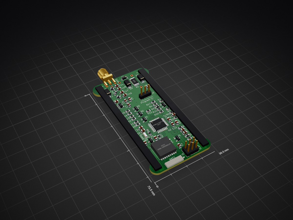
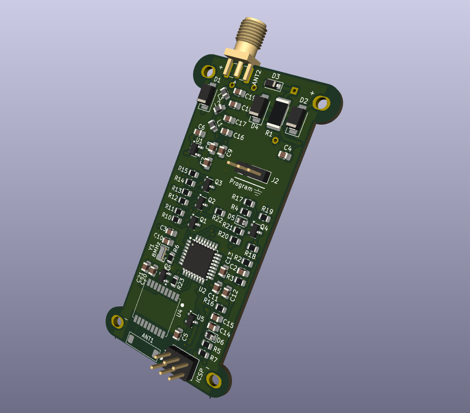
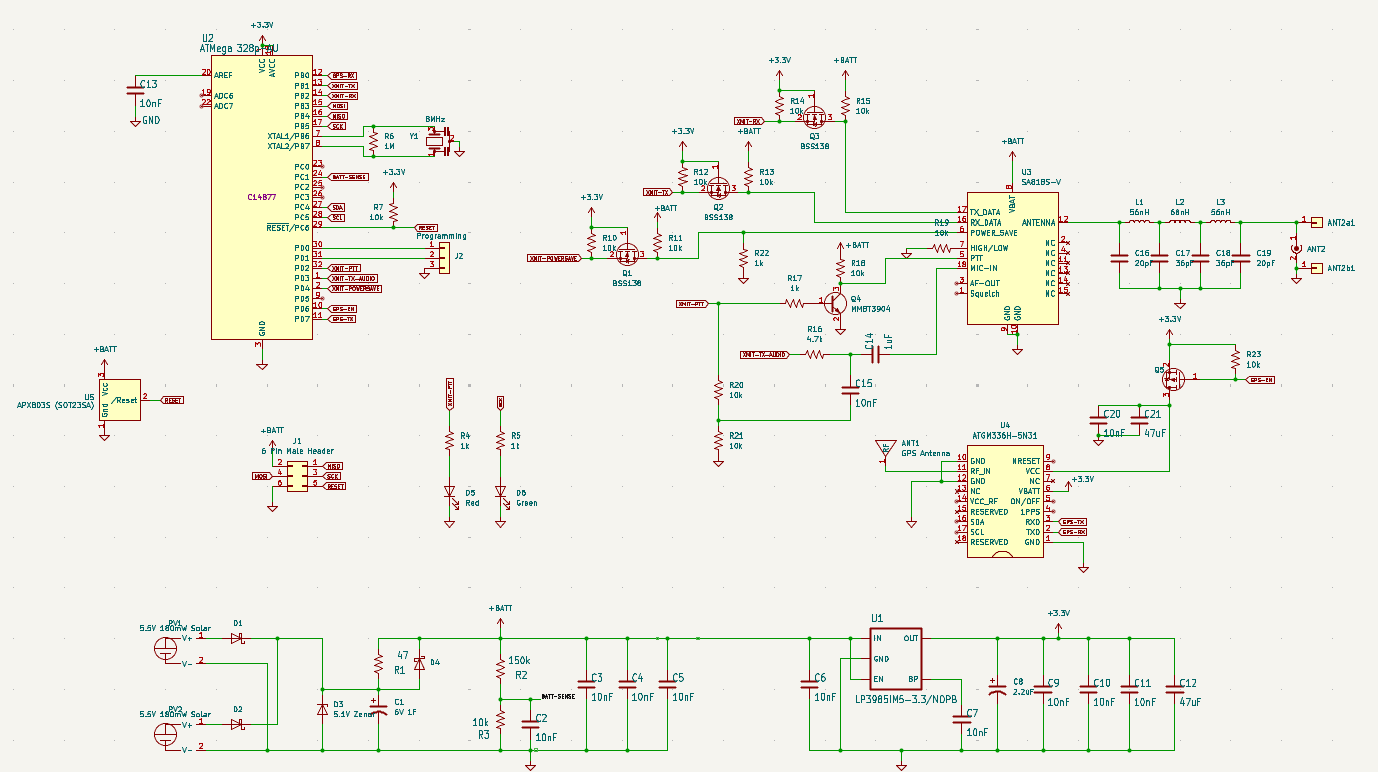
Under the hood, the ptSolar runs on the same Microchip ATMega328p microcontroller that the other trackers have been using for years, although this board runs at a lower 3.3 volt level, and a slower 8MHz clock speed.
PtSolar is an open-source printed circuit board by custom-ds, from the custom-ds/ptSolar repository on GitHub, published under the GPL-3.0 licence. It is a 4-layer board of 38.5 × 73.5 mm with 70 parts on 68 nets, routed with 395 tracks and 70 vias.
It is built around the ATGM336H-5N31, SA818S-V and BSS138, with the MMBT3904 among its other parts. Its parts include 21 capacitors, 21 resistors, 6 diodes, 5 ICs and 5 transistors. It belongs with the AVR (ATmega, ATtiny) boards of this library.
The ptSolar is the newest version of Project: Traveler's series of APRS trackers. The ptSolar has been designed and optimized for low-power operation, especially when using a solar panel.
Under the hood, the ptSolar runs on the same Microchip ATMega328p microcontroller that the other trackers have been using for years, although this board runs at a lower 3.3 volt level, and a slower 8MHz clock speed.
A 2m VHF transmitter is provided by the SA818S-V transmitter-on-a-chip system, which means it's frequency agile and can be used throughout the world.
The GPS receiver is utilizes the ATGM336H GPS engine which has a light-weight footprint while being a cost-effective solution. The ATGM336H is capable of position reports in excess of 60,000', making it a suitable solution for high altitude (latex) balloons traveling to over 100,000'.
The Circuit Board
The circuit board is designed in Kicad and features a 4-layer design with castellated solder points for the attached solar panels.
The ptSolar is currently in the prototyping stages. Version 1.1.0 of the PCB was the initial design that was first built in early 2025, and includes the ATMega328p microcontroller, an ATGM336H GPS receiver, and the SA818S-V VHF transmitter. VHF signal filtering is provided by a 3-pole pi filter, reducing spurious harmonic output to well within Part 97 specifications.
The Breakout Board
A Breakout board has been developed that can be temporarily or permanently paired to the top of the ptSolar tracker. The breakout includes a second ISCP programming port, a second serial data interface for configuring the tracker, a Sparkfun Qwiic connector for interfacing with other I2C sensors.
There is also a 2.1mm barrel jack for accepting power from a battery pack, along with the required 5V regulator when operating at higher supplied voltages.
The Breakout Board mates to the tracker with a female .1" header connecting into the 6-pin (ISCP) and 8-pin (Serial, I2C) plugs on the ptSolar.
Preparing the IDE for the Firmware
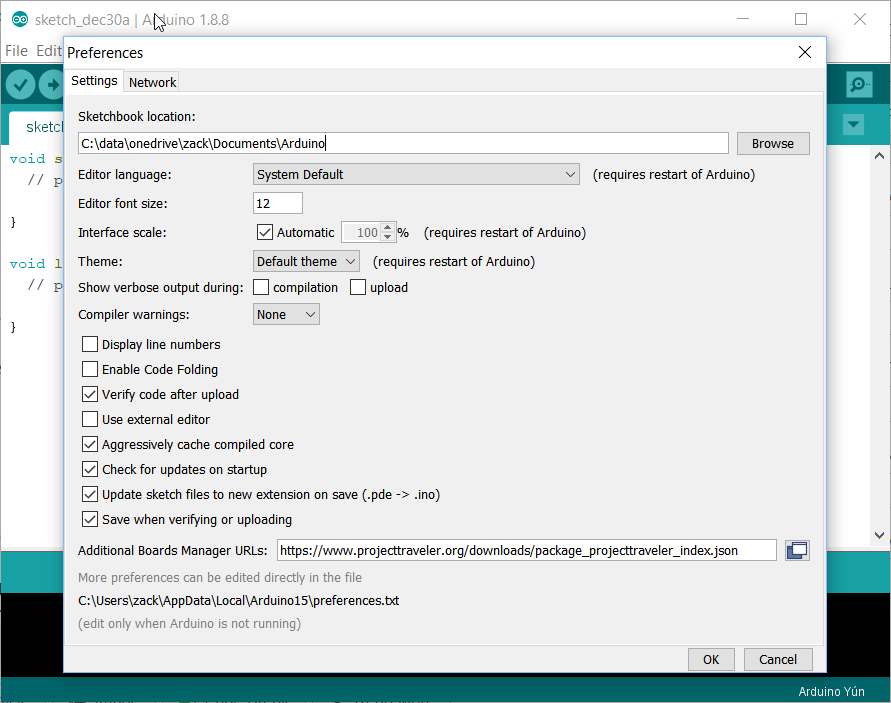
In the Arduino IDE and go to File → Preferences. In the Additional Boards Manager URLs field, add the URL to the Project: Traveler website .json file:
Note that if there's already something in that field, you can click the small icon to the right of the text field where you are allowed to enter multiple entries on multiple lines.
Click OK to close the preferences dialog. Then go to Tools → Boards → Boards Manager.
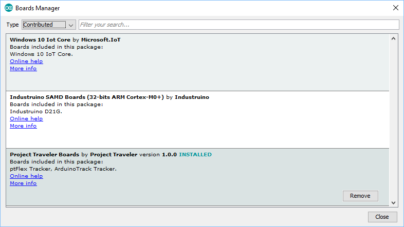
When the Boards Manager opens, select "Contributed" from the Type drop-down. In the resulting list, you should find the Project Traveler Boards by Project Traveler option. Click the Install button in the lower-right corner.
Close out of the Boards Manager dialog, and the back under Tools → Board, you should see "ptSolar Tracker (Arduino as ISP)" near the bottom of the list.
Setting the Controller Flags
If this is a brand new ptSolar board that has never been programmed before, there are several commands that must be run from a DOS command prompt. If the ptSolar was purchased as an assembled and tested kit, you can skip these steps.
The fuses are to be set as follows:
Low: 0xFF
High: 0xD6
Extended: 0xFD
To program the fuses using the AVRDude tool (which is included in the Arduino IDE, and works with the Arduino As ISP programmer), open a command prompt on the PC.
* Replace "comX" with whatever Com port your ArduinoISP is enumerating on.
Verifying the Fuses
text
C:\...> avrdude.exe -p m328p -b 19200 -c avrisp -C ..\etc\avrdude.conf -P comX* -U lfuse:r:lowfuse:h -U hfuse:r:highfuse:h -U efuse:r:exfuse:h
C:\...> type lowfuse
C:\...> type highfuse
C:\...> type exfuse
* Replace "comX" with whatever Com port your ArduinoISP is enumerating on.
Loading the Firmware
To program the ptSolar, open the firmware Sketch in this GitHub Repository in the Arduino IDE.
Go to the Tools → Board menu, select the "ptSolar Tracker (Arduino as ISP)" from the list of targets.
The ptSolar boards are automatically configured to use the Arduino as ISP programmer to load the firmware onto the tracker boards, so no further configuration is necessary. Click the Upload button which will cause the Sketch to compile and will program to the ATmega328 processor similarly to how a normal Arduino board is programmed.
Sometimes it is necessary to apply external power to the ptSolar Tracker, depending on how much current the Programmer board is capable of sourcing.
Under the hood, the ptSolar runs on the same Microchip ATMega328p microcontroller that the other trackers have been using for years, although this board runs at a lower 3.3 volt level, and a slower 8MHz clock speed.
Jag board is an attempt to make a pcb which can be used to control different kinds of rc vehicles. At first the focus will be on rc cars, which can be controlled via a web interface and a webcam.
RouteSync is a compact, LoRa-based communication device designed for long-range messaging and emergency location sharing in environments where cellular networks are unavailable.
KiCad and related artifacts for a WSPR tracker based on Traquito/Jetpack
84 parts1
Questions
How big is the PtSolar PCB?
It measures 38.5 × 73.5 mm and has 4 copper layers, 1.6 mm thick.
What parts does the PtSolar use?
70 parts, built around the ATGM336H-5N31, SA818S-V, BSS138 and MMBT3904. The full list of its parts is on this page, with links to each part's symbol and footprint where PCBKit's library has them.
Where can I download the PtSolar KiCad files?
From the custom-ds/ptSolar repository on GitHub, at the commit this page was made from: the board is ptSolar/ptSolar.kicad_pcb and its schematic ptSolar-Breakout/ptSolar-Breakout.kicad_sch. PCBKit opens the board in the browser, with nothing to install.
Can I use the PtSolar design in my own project?
Its repository publishes it under the GPL-3.0 licence: you may reuse it on that licence's terms (keep the author's notice, and for a copyleft licence share your changes alike).